Product: MJP Print Industria: Medical and Forensic
Not long ago one of the realities of the medical device industry was that a company had to have a large footprint to reach the market with an innovative product.
But an emerging generation of small companies is using a laser-focus on their product niche and new technologies such as 3D printing to break through the barriers of the past.
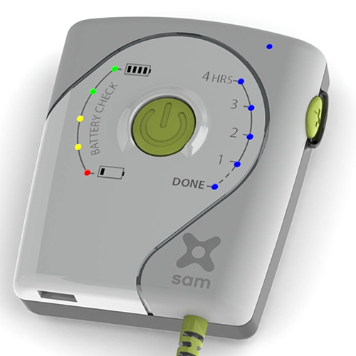
ZetrOZ is a prime example. The company, privately funded with about 20 employees, late last year introduced sam®, the world’s smallest ultrasound therapy system that provides an alternative to pharmaceutical-based pain treatments.
sam stands for Sustained Acoustic Medicine, a suitable name for a device delivering long-duration, continuous ultrasound therapy that’s completely drug-free and cleared by the FDA. According to ZetrOZ, the deep-penetrating ultrasonic therapy—available only before in large, expensive machines located in the offices of healthcare providers—reduces inflammatory pain, relieves muscle spasms, improves joint and muscle flexibility, and increases local circulation.
3D prototypes like the real thing
After nearly a year on the market, ZetrOZ needed to design a new version of sam, with the emphasis on making the casing for the device more aesthetically pleasing, both to the eye and the touch. ZetrOZ also wanted to ensure that sam can withstand the rigors of everyday use in a home environment, which could include everything that typically happens to a cell phone: people sitting on it and dropping it, cats playing with it, dirt, dust, humidity, moisture—you name it.
The updated design work was done with help from the Connecticut Center for Advanced Technology Inc. (CCAT) and a funding grant through Connecticut’s Manufacturing Technical Assistance Program, a state-legislature supported program.
CCAT uses the ProJet® 5500X (now sold as the ProJet 5600) printer to quickly produce multi-material prototypes that are not just approximations of actual products, but that look and feel exactly like injection-molded parts.
“The ProJet 5600 is a unique 3D printer,” says Eric Wold, CCAT machining applications specialist. “It has the ability to blend materials within a single part build. It is especially good for parts with over-molded features, such as a rubber grip on the outside of a handle or case.”
For ZetrOZ, the over-molding capability is critical for creating a rigid case that provides a comfortable, tactile feel.
“Working with CCAT and its 3D Systems’ printer gives us access to a wide range of printed materials,” says ZetrOZ’s Eric Kolb. “We can experiment with different material properties for strength, flexibility, surface finish, comfort and resolution.”
CCAT has developed sam prototypes using three different materials from 3D Systems: VisiJet CR-WT, a white, ABS-like material; VisiJet CR-CL, which is clear and has the translucence and strength of a polycarbonate; and VisiJet CF-BK for the over-molded areas that require a rubber-soft gripping surface.
Iterations in half the time
Over the past several months working on the new version of sam, the two Erics have leveraged 3D printing technology to forge an easy-going, clearly defined relationship.
“Basically I send a SOLIDWORKS CAD file to Eric and he does the rest,” says Kolb.
Wold converts the CAD file into STL format and loads it into 3D Systems’ 3D Sprint software to lay out the parts on the ProJet 5600 build plate. When the parts come out of the printer they are placed in an oven to remove wax used during the build process, cleaned with mineral oil in an ultrasonic machine, and gently washed with hot water and a mild soap.
ZetrOZ is refining a favored design and materials after about six vastly different design concepts were considered. It takes about a week, including shipping, for CCAT to return a 3D-printed prototype for each iteration, according to Kolb.
“If we were using a traditional injection-molding process, each prototype could take eight to 12 weeks to build and we’d probably only have time and money for one design iteration,” says Kolb. “Some new molding processes can reduce that time to a couple of weeks, but that’s still twice the time it takes us working with CCAT and its 3D Systems equipment, software and materials.”
“The quality and the detail of the 3D printer are amazing,” says Wold. “We have had people visit our facility who have been 3D printing for years and they cannot believe the fine details the printer is capable of. Parts that come out of the printer look like finished production parts, not 3D-printed prototypes.”
Skin in the game
The new, improved version of sam is not just a professional concern for ZetrOZ’s Kolb. As a runner and triathlete who has suffered from chronic injuries, Kolb is using sam to get back in shape for future competition. He’s benefiting from the controlled-release, long-duration treatment provided by sam, using the device up to four hours a day, five days a week.
“In the past I’ve never been able to use products I’ve worked on because they were for surgical procedures,” says Kolb. “It’s nice to be designing something I can touch and operate as an end user.”
Kolb expects that the more rugged and cosmetically pleasing sam will be released in the first part of 2016, providing another example of how, with the help of 3D printing, big ideas from small companies can come to market faster and less expensively than ever before.
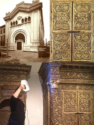
The Holy Torah Ark of Mantua is one of the rarest and most impressive exhibits at the Nahon Museum of Italian Jewish Art in Jerusalem. Designed to house the holy Torah scrolls and created by the finest craftsmen of Mantua, Italy in 1543, this unique wooden ark decorated with the original gilded carving is one of the oldest in the world. Its style echoes that of the biblical Holy Temple in Jerusalem, which is believed to have housed the Ark of the Covenant. It was designed in the shape of a building and features architectural elements such as columns and capitals.
From the time of its construction to the present day, the Mantua Ark has undergone multiple incarnations. Finally, after World War II, with a declining Jewish community, the ark was shipped to Jerusalem and placed in its present abode. Once there, it underwent extensive renovation, preservation, and restoration, all of which brought it back to its wonderful present condition.
For an ordinary visitor to the museum as well as visitors to the museum’s website, however, the ark’s special history in regards to its symbolism and features remains unknown. Its size and position prevents close inspection and even the features which are visible cannot be fully appreciated.
In 2015, the Nahon Museum initiated a project designed to tell the story of the ark, its journey, and its historic meaning in the context of Jewish Italian life. The website Mantua in Jerusalem outlines the history, life, and culture of the Mantua Jewish community and the importance the ark held to its people, generation after generation.
It was for this reason that the museum chose to embark on an ambitious endeavor – to 3D scan the ark and make it fully accessible to visitors, both in person and virtual.
Due to its size, geometry, and the complexity of its texture, the scanning of the Mantua Ark posed certain challenges:
The topography of the ark – extremely complex, with numerous areas without direct visual access. In addition, the ark stands so close to museum walls it left very little room for the scanning equipment to work, as well as operating the scanner at the angles required to reach the blocked surfaces.
The texture. The ark was initially made of wood. However, its entire surface is coated in a gold leaf, which is smooth and shiny – one of the most hard-to-capture surfaces for any 3D scanner. When it came time to do the scanning, it was neither permitted nor practical to coat the surface with matte powder. Even if it were, it would have altered the surface quality of the ark.
Thirdly, while the topography of the ark is complex, the texture is very symmetrical and the pattern is repetitive, which somewhat complicated aligning and fusing the multiple scans.
And finally, the size of the ark (over 3 meters high) made the scanning process all the more challenging.
After assessing the complexity of the job, it became clear that the highest-quality tool is needed to digitize the ark, and the museum turned to Caliber Engineering and Computers Ltd, Artec 3D’s Gold Certified Partner in Tel Aviv. Zvi Grinberg, head of Caliber at the time, was immediately brought into the project. Being so different from the technical engineering CAD projects his company usually undertook, he recognized both the professional challenge and the unique cultural value of this project, which he volunteered to take on at no cost.
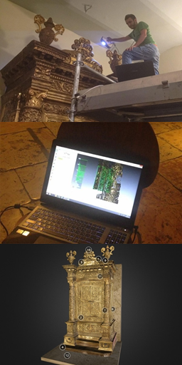
After a thorough examination of the ark, the Caliber team decided Artec Eva was the most suitable scanner for the job. Called “a monster among handheld scanners,” this structured-light 3D scanner excels at capturing medium-to-large objects with an outstanding accuracy of up to 0.1 mm and exceptional resolution, even for black and shiny surfaces, which gives it an edge over other scanning solutions on the market. Plus, it is lightweight and fast, which makes it especially helpful when capturing diverse historical pieces, sculptures, and monuments in far-from-ideal scanning environments, whether on a sunny day outside or deep within a dimly lit gallery.
To capture the ark from the ground up and give the scanning team easy access to the top of the object, special scaffolding was built in the museum. Normally used for medium-sized objects, it was a personal challenge for Eva to capture such a large object. It took 15 hours over three days for the team to complete the scanning, followed by several more to align, clean, and fuse the multiple scans together. Overall, 78 separate scans were made. The final model was over 700 MB and contained over 16 million polygons.
“Despite the ark’s large size, we’ve managed to get good results with Artec Eva right from the first attempt thanks to the texture and geometry of the ark. After the scan, we were able to finish all the work at the office using Artec Studio software, with no need to come back for additional scans and repair,” said Guy Engel, CEO of Caliber Engineering.
After the initial processing stage, the Caliber team reduced the size of the file while maintaining the quality of the original scans, and touched up the 3D model to prepare it for public display. At this point, the file was passed on from Caliber to the Department of Photographic Communication at the Hadassah Academic College in Jerusalem, to Associate Professor Moshe Caine specifically. Having extensive knowledge and experience in 3D scanning and photogrammetry solutions for cultural heritage preservation, Professor Caine polished the 3D model of the ark to the peak of perfection.
Professor Caine’s scan processing workflow went as follows:
Fine-tuning and cleaning minor defects of the mesh using Autodesk (beta) Memento Software.
Adding in a back wall and floor. Because the ark was mounted to the museum wall, it was impossible to scan the back and underside of the ark. Rather than construct a false rendition of them, it was decided to computer generate a simple wall and floor and add them to the model.
Image processing of the texture map. Despite the meticulous work during the scanning stage, small defects still remained, as well as an inaccurate color rendition of the ark. Additional photography was subsequently carried out using a DSLR Nikon camera, and the corrected surfaces were fused into the original UV map. Various methods were tested for this purpose, including:
Parameterization and texturing from rasters in Meshlab.
Exporting the map as a PSD (Photoshop) file, correcting in Photoshop, reimporting to and then exporting the corrected model.
Opening the OBJ file in Photoshop and working directly on the texture layer. Ultimately, a combination of the above techniques was employed until satisfactory results were achieved.
Color correction was carried out on the final texture map with Photoshop software, using the actual ark as the sole reference.
After scanning dozens of historical pieces, Professor Caine elaborated on his approach to the 3D scanning and processing workflow:
“One major piece of advice (for those planning to 3D scan cultural heritage) is this: work slowly and carefully. Don’t hurry. Move in as close as possible to the object. Use lots of soft light. And remember the saying: ‘Garbage in… garbage out.’ The result will only be as good as the work and care that goes into it.”
When Professor Caine finished his meticulous scan processing, the final model was uploaded for public viewing to the Nahon Museum website Mantua in Jerusalem, dedicated to the art of Mantua’s Jewish community. In addition, an onsite kiosk with a touchscreen was installed next to the ark, making it possible for museum visitors to view the magnificent historical showpiece from all angles, zoom in and out to examine every detail, and most importantly, to have immediate access via hotspots to the relevant information for various aspects of the historic artifact.
The overall response to the model has been very positive and enthusiastic. According to the museum’s personnel and Professor Caine, people particularly appreciate the ability to explore the ark up close and from all angles. This is the magic of 3D models, which 2D images or even physical objects as large as the Mantua Ark normally cannot compete with. Projects such as this are an amazing example of how 3D scanning technologies transform the way we perceive and can preserve cultural heritage.
Back in the 1500s, the citizens and members of Mantua’s Jewish community couldn’t even imagine that their descendants would one day not merely be able to see their community’s signature artifact all in one piece, even after 500 years, but also be able to explore it up close in 360 degrees without even leaving their homes.
Product: NX CAD Industry: Electronics and Semiconductors
Using NX Open to automate iterative design and analysis processes results in highly efficient, standardized operations.
Engineers helping engineers
Founded by three United Technologies engineers in 1995, Design Automation Associates Inc. (DAA) offers a variety of engineering consulting services, with a focus on helping companies automate their product development and configuration processes. The firm, which now has a staff of 20, serves a wide range of industries, including rotating equipment, electronics packaging, industrial machinery, aerospace, military and automotive.
DAA has a great deal of experience in determining which activities are suitable for automation. One of the most promising involves the design and analysis of engineered-to-order (ETO) and configured-to-order (CTO) products. “Iterative problems occur in all areas of engineering design and analysis, but they especially occur in companies with engineered-to-order and configured-to-order products where certain parts are designed so repetitively that automation can provide huge time savings,” says John Lambert, president and CEO of DAA.
As a specific example in electronics packaging, Lambert points to the finite element analysis (FEA) that must be performed for ETO printed circuit boards (PCBs). “For every new order, these companies have to re-engineer their circuit boards. Even when companies use good analysis technology, there is still a lot of work that must be done by hand,” Lambert explains. In many cases, manual calculations are needed to deter-mine loads, for example, and to assess the results of an analysis. “Many of those calculations, such as those used to interpret results, involve specialized procedures that are part of a company’s intellectual property that makes it unique and able to compete,” Lambert continues. “There is a whole domain of logic and calculation that won’t be added to any analysis software as out-of-the-box functionality, because it is company-specific.”
DAA has seen situations where the analysis process for a single ETO product took as many as 40 hours. “And a company might perform that same analysis process 100 to 200 times a year,” Lambert says. “In addition to the time and expense incurred, having to rely on so much manual calculation introduces the likelihood of error.” Whenever DAA does see attempts at automation, it’s almost always in the form of macros, which are, as Lambert points out, “twenty-year-old technology.”
Way beyond macros
DAA engineers use a number of advanced design and analysis solutions in their work, but when it comes to automating complex, iterative analyses and design-analysis loops, the firm relies on Simcenter and NX software from Siemens Digital Industries Software. DAA uses Simcenter 3D and Simcenter Nastran, both part of the Siemens’ Simcenter portfolio, for advanced analysis. “The Simcenter and NX toolset is world-class functionality,” says Lambert. “With Simcenter 3D and NX, we get integrated modeling and analysis capabilities, as well as NX Open.” NX Open is the application programming interface (API) embedded within both Simcenter 3D and NX. DAA uses NX Open, along with some custom coding, for its more complex automations. “The problems we’re focusing on require complexity and automation beyond that supported by out-of-the-box capabilities,” says Lambert. “For that we use NX Open.”
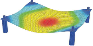
As an example of the automation DAA has done, Lambert describes a finite element analysis of a PCB destined for use in an aerospace application. “This is a great example of a task that must be done iteratively, in part because there are so many design variables, such as the components on the board and the mounts, that can be changed,” Lambert explains. “Also, the boards are subject to random vibration, and depending on the spectrum there can be one or more keep-away zones. You need to iteratively move frequencies to get them away from “keep-away zones” and into areas of lower vibration, but it’s not that simple because you can increase loads and stresses by doing that. When you move frequencies, you have to reassess loads. And often in electronics packaging there are components that have frequencies close to each other, so they magnify each other. It becomes an exhaustive, iterative game to achieve the balance between proper frequency placement and the structural board integrity.”
DAA’s automated version of this process, which looks to the user like native NX functionality, includes geometric modeling, FEA preprocessing, postprocessing and analysis using Simcenter 3D and Simcenter Nastran® software. Starting with the NX geometry model of the PCB, the program automatically creates the finite element mesh and applies the appropriate material properties. Then it iteratively runs a frequency extraction analysis (Simcenter Nastran Solution 103). Custom code written by DAA using NX Open compares the results to the random vibration spectrum, and then continues the iterative looping and modifications to the PCB geometry until the PCB vibration frequencies are out of the keep away zone on the random vibration curve. Next, custom calculations are done to determine loads, followed by analyses of stresses and deflections (Simcenter Nastran Solution 101). Some additional custom code combines those results with industry and process knowledge to generate life predictions, make comparisons against material allowables, and ultimately determine whether the design is acceptable. If not, the process starts again and the iterations continue until the design has adequate structural integrity.
In this example, Lambert notes that thermal analysis is not involved, although it could be: “Generally there is thermal analysis that has to be done and it can be included in the automation as well.”
Huge time savings and fewer errors
One of the most obvious benefits of automation, as illustrated in the PCB example, is the time it saves. Lambert has seen situations where an analysis that previously required 40 hours is now done by the automated process in 15 minutes.
Of course, creating the automation takes time, and DAA has a good rule of thumb for estimating how much time. “It takes approximately 10 times as long to create a somewhat robust automation routine as it does to run a single iteration,” Lambert explains. “So not everything is appropriate for an automation. If it’s an analysis that a company will run only a handful of times, it’s probably not worth it. But if it’s some-thing they’re doing 25 or 100, or 200 times a year, it makes a lot of sense.”
What skill level is needed to create an automation such as the one he described? “You need someone who has a moderate level of programming capability,” Lambert says. “The journaling function will generate a lot of NX Open code for you, but you need to know how to open that code, edit it and enhance it so it’s more suited to a general-purpose application, instead of just recording keystrokes.”
There are several other benefits to auto-mating iterative simulation processes with Simcenter 3D. Automations maintain the NX look and feel, so users who are comfortable with NX CAD need minimal training to use them. Also, once processes are automated by expert analysts, they can be run by users with less education and training, freeing up analysts for more challenging projects. Automating a process also has the effect of standardizing it and eliminating human errors, such as analysts’ mistakes in hand calculations.
DAA has had so much success using NX Open automation that it surprises Lambert that more companies aren’t taking advantage of the software’s programming functionality. “There is very powerful capability in NX and Simcenter but we rarely see it used even though there is a great need for this kind of automation among our customers,” he says. “In the right situations, automating simulation processes within the NX CAD environment could be well worth the investment.”
Product: Tecnomatix Industry: Automotive and Transportation
Tecnomatix Plant Simulation models give planners more flexibility; material flow simulation also increases output and reduces waste.
Making driving safe and comfortable
Continental Automotive GmbH is one of the leading automotive suppliers in the world. The company’s three divisions – Chassis & Safety, Powertrain and Interior – develop and manufacture products that make driving safer (air bags and sensors; brake and chassis control systems), more fuel efficient (gasoline and diesel injection systems) and more fun (infotainment systems and multifunctional displays).
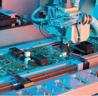
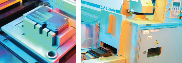
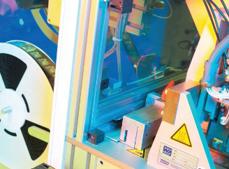
The company’s Regensburg, Germany facility is its biggest electronics plant. In an area of 16,500 square meters (approximately 177,000 square feet), nearly 2,000 employees produce about 67 million electronic devices per year. The plant operates 24/7, running 22 lines for surface-mounted devices (SMDs) along with other product-specific assembly and inspection lines.
The company’s different business units demand quite a lot from the manufacturing planners at the Regensburg plant. Frequent product alternations as well as quantity changes require repeated production line adjustments. To support the planners in this complex effort, the plant established an internal consulting agency, called the “Lean Office,” that provides the business units with an expert production infrastructure and manufacturing expertise. “We offer our customers, the individual business units, a kind of carefree package for the manufacturing of their products,” says Dr. Markus Fischer, head of industrial engineering at Continental Regensburg.
Identifying problems through simulation
The Lean Office increasingly relies on advanced technology, such as the Tecnomatix® software from Siemens PLM Software. This digital manufacturing solution was chosen after a rigorous benchmarking process – involving the production process for side airbag satellites (sensors used to detect an impact) – that turned out 120,000 parts per day, covering more than 200 variants. The task was to simulate material flow between processing stations, starting with preliminary assembly, through to SMD mounting and all the way to customized packaging. After the process was modeled in Tecnomatix Plant Simulation (in two weeks), the resulting simulation won over the plant’s management, and Tecnomatix software was quickly integrated into the Lean Office’s technology portfolio.
The office uses the Tecnomatix material flow simulation functionality to examine and optimize new production lines, as well as to optimize existing ones. The lines can be evaluated and optimized for various parameters, such as throughput, cycle times, performance limits, interferences, and so on. To make reliable predictions, simulation models must map the real line as accurately as possible. Also, modifications must be tracked carefully. Given the frequent product alternations, the goal is to quickly identify potential problems in software and fix them before the actual process begins. “With a simulation, many problems are easily fixed,” explains Stefan Lamken, a process consultant to the Lean Office and key user of Tecnomatix.
Normally at Regensburg Plant, the manufacturing planners design lines with precise and successive processing stations. In this context, a simulation model is used to verify the planned performance of the line. “For our planners, Tecnomatix Plant Simulation is a very interesting tool,” says Fischer. “An offline simulation shows solutions that sometimes surprise even the most experienced colleague.” For example, a multi-product line with up to 100 variants did not reach the theoretical targeted output. An unforeseen bottleneck unbalanced the material flow. The Tecnomatix simulation showed that a processing station was operating too quickly, resulting in jams at subsequent stations. The unexpected solution – slowing down the cycle for that particular station – would have been discovered much later had the simulation not been used.
Supporting sound financial decisions
In another situation, the goal was to increase the output of a production line. Manufacturing planners developed four possible scenarios, noting the cost of each possibility. By evaluating the four alternatives using Tecnomatix simulations, the company was able to see that the most economical approach would meet the desired goal. “We were elated with the software,” recalls Lamken. “With it, we could see that the cheapest concept delivered as much additional output as the most expensive one.” Overall, this is one of the key advantages of the Tecnomatix solution: accurate performance data on which to base financial decisions.
Tecnomatix also saves money by eliminating the need for time-consuming tests on actual production lines. For example, an SMD line occasionally bottlenecked and jammed, requiring operator intervention to resolve the problem. This jeopardized product quality and affected the line’s performance. A cooling buffer solved these problems. A Tecnomatix simulation took the solution a step further by showing how the buffer could also enable higher output. This was determined without performing any physical tests. “The possibilities of a simulation are really great for reducing costs,” says Lamken.
In addition to verifying new and revised production processes, the Lean Office uses Tecnomatix to minimize stock and to reduce waste. Questions regarding the ideal number of work-piece carriers in a line are answered in detail by the soft-ware. At the same time, simulation makes it possible to consider the effects of various external conditions, such as potential supply disturbances and personnel changes. “With Tecnomatix we are able to evaluate various scenarios in the planning stages,” says Fischer. “With this capability, we have the necessary flexibility to perfectly meet customers’ demands.”
Currently, the Lean Office uses Tecnomatix Plant Simulation models on approximately eight projects per year, although that number is growing. “Every manufacturing planner who has experienced the benefits of simulation comes back to us and our services,” says Lamken. “Digital material flow simulation with Tecnomatix has enormous potential at our Regensburg plant.”
Restoration is a major undertaking. Beyond the painstaking care essential to preserve and stabilize historical structures, restoration includes lots of research and planning to return relics to a known or assumed state with as much integrity as possible.
When the Historic Royal Palaces (HRP) in the United Kingdom began its undertaking to restore The Great Pagoda, Kew, it faced some monumental challenges. Several key design elements from the original building had been lost to history, and replacing them quickly proved challenging in terms of cost, logistics and design. Yet by bringing the technologies and expertise of 3D Systems On Demand Manufacturing to this project, this effort was made not only manageable, but efficient.
Using a scan-to-CAD workflow with selective laser sintering (SLS) additive manufacturing, 3D Systems On Demand Manufacturing team delivered durable and repeatable fixtures for HRP’s restoration effort. Far from a hands-off process, the team contributed many hours of frontend engineering and backend finishing to provide high quality full-service design and manufacturing expertise.
A UNESCO World Heritage Site
Though popular opinion of King George III may be divided, there is no denying the impact of his 59-year reign. Beyond the countless volumes of extensive studies and films on his life and rule, his legacy is steeped into the very earth of the lands he governed – particularly at The Royal Botanic Gardens, Kew. A UNESCO World Heritage Site, the gardens are home to The Great Pagoda, a striking 163-foot structure commissioned in 1761 and built in ornate and highly fashionable Chinoiserie style.
In the years following the pagoda’s unveiling, it drew crowds of tourists who came to marvel at its exotic and eye-catching details. Central to all conversations were the 80 painted wooden dragons that adorned the octagonal corners of each successive level.
The talk of the town for more than twenty years, the Kew dragons were removed in the 1780s to accommodate roof repairs to the pagoda and were never replaced. Although rumors allege the dragons served as payment for royal gambling debts, experts believe the wood had simply rotted over time. An often revisited topic for conservationists, The Great Pagoda is finally being returned to its former splendor, dragons and all, for the first time in over 200 years. As part of a restoration project undertaken by HRP and the Royal Botanic Gardens, Kew, this batch of dragons is designed to stand the test of time with special reinforcement by modern technology.
Quality fit for a king
As HRP began to explore methodologies for replacing the dragons, it faced a dilemma: not only would wooden replacements invite the same longevity issue as before, but the pagoda had not supported the weight of the dragons for two centuries. “One of the most challenging aspects of this project was to minimize the impact imposed by so many dragons on this grade one listed building,” said Craig Hatto, Project Director at Historic Royal Palaces. Concerned that the aged structure may respond poorly to the sudden reintroduction of 80 full-weight, large-scale ornaments, HRP wanted to explore a lighter-weight alternative to help guarantee a successful and incident-free installation. Paired with these practical considerations were the equally valid issues of the time and costs associated with traditional materials and processes.
HRP was looking for a restoration solution that would answer the quality, weight, time and cost concerns inherent to the project. In searching for a supplier capable of delivering on all aspects, HRP asked 3D Systems to submit a competitive tender, which it subsequently won on the basis of being able to provide the expertise, technology, quality and scalability required to fulfill the project.
Designing the dragons
The Kew dragons were brought to life as a collaborative effort between two sets of specialized designers. The exterior appearance of the dragons was recreated by HRP using the scarce historical information available to achieve the most accurate representation possible. Once designed, a dragon prototype was carved from wood to enable the digital manufacturing workflow that followed, undertaken by the second design and engineering team at 3D Systems. Seven additional wooden dragons were carved to adorn the first level of the pagoda, leaving 72 to be created using SLS printing.
Using a reverse engineering workflow and a FARO® Design ScanArm, the carved wooden dragon was scanned into a 3D design environment that would allow 3D Systems to address HRP’s concerns regarding weight. 3D Systems’ design experts used a variety of software including Geomagic® Design X™ to reverse engineer the scan data into CAD and hollow the scan data to a controlled thickness, preserving both the exterior details and structural integrity in the process.
When combined with the intricate exteriors of the hand cut masters, the resulting hollow geometry was too complex to be manufactured traditionally and required additive manufacturing for production. Using a digital manufacturing workflow also enabled 3D Systems to seamlessly scale the dragons to achieve a slightly different size for levels two through ten of the pagoda. In total, 18 designs were prepared, comprised of nine different dragon sizes and a left- and right-hand version of each.
3D Systems’ engineers incorporated another simple yet compelling feature into each of the dragon designs by adding built-in mounting features directly into the CAD files. These designs constituted part of the dragons’ construction designs, and were devised and implemented by 3D Systems’ On Demand Manufacturing team in close collaboration with Hockley & Dawson, the other lead engineering team on the project. Due to the mechanics required for reinforcement and mounting, each of the 18 dragon variations required individual attention and design work.
“The final dragons are essentially a perfect copy of the original, but have been improved upon in a way that is invisible to the observer,” said Nick Lewis, General Manager UK, 3D Systems On Demand Manufacturing. “We engineered internal elements for a secure mounting process, but designed them in such a way as to be completely concealed so no nuts, bolts or traces of construction will be visible.”
Hidden benefits of additive manufacturing
Taking advantage of the ability to design for additive manufacturing, 3D Systems’ On Demand Manufacturing team incorporated a series of screws, threads and covers that follow the exact form of the dragons along the spine. “The final structures we delivered take advantage of the unique value that can be extracted from the additive process,” said Lewis. “Engineering in this way is common practice for us, but it is still miraculous to our customers. The wow-factor makes it fun to reveal, but to me it’s about being resourceful and solving problems more effectively and efficiently, which is a central benefit of using our technology.”
3D Systems’ engineering expertise is built into each of the 18 different versions of the dragons that were SLS printed. As 3D Systems On Demand Manufacturing Regional Sales Manager Simon Hammond points out, the ability to match precision with variety is a consistent benefit of using additive manufacturing for production. “Many hours of careful engineering work were put into the final designs, but by using a digital workflow with 3D CAD and 3D printing, we are able to frontload the time investment,” Hammond says. “Once final files were ready, we could launch into production with 18 different outcomes without 18 sets of tooling and molds. Designing and manufacturing the same outcome with good cost and sensible timing would be challenging for any other process.”
Following 3D scanning and design, early prototypes of the dragons were printed for analysis and testing to ensure the final designs were built in accordance with the stringent requirements of modern construction.
Throughout this process, 3D Systems worked diligently to deliver on the customer’s aesthetic requirements while meeting all the technical requirements of the builders. These considerations came into play as 3D Systems’ engineers determined how to best divide the SLS models for printing as well as position and conceal the various caps and closures for mounting.
Production 3D printing for historical restoration
3D Systems’ On Demand Manufacturing teams in the UK and the Netherlands printed the dragons using SLS technology. Due to the large scale of the dragons, each with final dimensions in the 1.2 – 2 meter range, 3D Systems sPro® 230 SLS machines were chosen for the task. With a maximum build volume of 550 mm x 550 mm x 750 mm, the sPro 230 enabled the dragons to be produced in a low number of large pieces that were expertly assembled by the 3D Systems team.
The dragons were 3D printed in DuraForm® PA, a durable polyamide 12 nylon material capable of producing a comparable look and feel to the original dragons. The resolution and mechanical properties of DuraForm PA make it an ideal candidate for complex parts with thin walls or snap fit requirements. In the case of the Kew dragons, these features suited both the functionality requirement of installation as well as the cosmetic requirements of the historic restoration. Once printed, the dragons were finished and hand painted in the UK by the 3D Systems High Wycombe finishing department. 3D Systems’ team also painted the final wooden dragons to ensure visual consistency across the project.
“3D Systems is greatly honored to have been selected for this project,” said Lewis. “In addition to the rare opportunity to help restore a cultural and historical landmark, this project showcases the extreme element of what we do. Our expertise extends far beyond 3D printing and we were able to offer guidance across multiple stages of this restoration, from engineering and scalable production through to finishing.”
The big reveal
After standing for 200 years without its proper ornamentation, The Great Pagoda, Kew, will finally be restored to draw curious crowds once more. “Over the decades, many have tried and failed to recreate the lost dragons at Kew, which has now only become possible through the innovative use of 3D printing,” says Hatto. “The specialist team developed an innovative, lightweight and durable solution, which has ultimately allowed us to return these lost icons to this treasured royal building. The dragons can take their rightful place within this UNESCO World Heritage Site and once again be part of the London skyline for many years to come.”
Whether you are seeking full reverse engineering and low volume manufacturing services or need fast turn 3D printed parts, advanced prototyping or appearance models, 3D Systems On Demand Manufacturing can help. Technologies include a broad array of 3D printing technology and finishing expertise as well as conventional CNC, urethane casting and injection tooling.
Product: CAM Pro Industry: Industrial Machinery and Heavy Equipment
Using Solid Edge with synchronous technology and the 5-axis machining functionality of CAM Express, The Te-Shin Cam significantly improves its ability to meet its customers’ needs
Critical CAM components
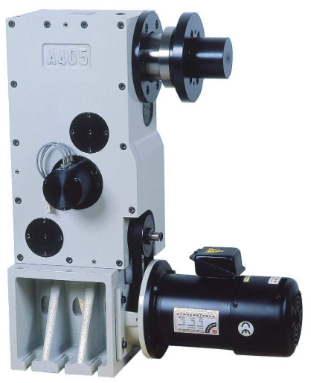
Established in 1980, The Te-shin Cam Co., Ltd. (Te-Shin) is devoted to the design and production of equipment related to computer-aided manufacturing (CAM). Its product line includes critical components, such as automatic tool changers (ATCs) and intervallic cutters.
Te-Shin boasts a large production capacity for this equipment, with a monthly output of up to 3,500 tool changers. It has become a leading industrial supplier of precision machinery in its region, and accounts for 85 percent of the Taiwanese market in its segment. The company’s intervallic cutter features high quality and an excellent cost-performance ratio, and sells for half the price of products imported from Japan.
In recent years, to meet the requirements of high-end, high-precision industries, Te-Shin invested in professional equipment for machining and grinding and adopted an advanced research and development (R&D) process based on 3D design. However, because the previous computer-aided design (CAD) system one of the industry’s leading technologies – used a traditional modeling approach, the company found it difficult to deal with customers’ design changes in real time. This led to a search for a better solution, one that would deliver integrated design, manufacturing and data management functionality to enhance the company’s competitive edge.
Easy to learn and use
After careful assessment, Te-Shin adopted Solid Edge® software from Siemens PLM Software for the drafting and design of all new tool changers. Designers find the new software to be easy to learn and use com-pared with its prior system, which involved complicated instructions and objects inter-related in a hierarchy. Designers found that system dull and time-consuming to use.
In contrast, use of Solid Edge provides an intuitive interface and a component library – a great improvement that allows designers to focus on the design of important system architectures. “What’s more, even our chairman can now easily draft some basic drawings using Solid Edge,” says Cai Peirong, deputy director of the R&D department at Te-Shin.
With Solid Edge, users can import the company’s legacy CAD drawings and manage those files, along with native models created using Solid Edge, thus reducing design and modification time, and decreasing miscommunication between design and manufacturing.
“In the past, in considering whether to adopt 3D design for new product development, our colleagues took the product life-cycle and timeliness into consideration,” explains Peirong. “But the ease of use of Solid Edge, along with the cutting-edge synchronous technology, enables us to use both 2D and 3D data effectively, which furthers the full acceptance and implementation of this new-generation, 3D design system.”
The new system was first used to provide 3D exploded views as required by customers for the purpose of including specifications in maintenance manuals. According to Peirong, “When using the previous 3D software, it normally required three days to draft an exploded view. Using Solid Edge, this is done in one day. Modifying a 3D model is as simple as modifying 2D drawings. We save valuable time.”
In addition, the adoption of synchronous technology means that design data can be updated quickly, which is an important benefit. “The synchronous modeling function allows us to update the change to the assembly drawing as we are changing the part drawing,” says Peirong. “This synchro-nous update capability effectively eliminates the consequence of changing the part drawing only and leaving the assembly drawing unchanged, which consequently might lead to errors in the subsequent operations.”
Error-free tool sequences
“In the past, when we used 2D design, there would always be blind angles during product development, which then might lead to collisions,” says Peirong. “In the worst cases, the whole mold would have to be rejected or destroyed. But with Solid Edge, we have effectively addressed the issue of drafting simulation, and avoided interlinked collisions.”
Now, once a design is finished, designers transfer it to a 2D drawing, then deliver it for mold unfolding and machining. At the machining stage, the company uses CAM Express software from Siemens PLM Software, and finds the 5-axis machining capability of CAM Express to be particularly beneficial.
One of the most prominent benefits that the 5-axis machining technology brings is a reduction in errors in tool sequence programming. The company’s original tool changer was manually programmed. Because the machining operation is com-plicated and lengthy, manual operation easily led to errors, and there were different results based on the different skill levels and experience of the operators.
“In the past, the experience of operators easily influenced the accuracy of machining. There were normally hundreds of lines of handwritten programs, and the programming logic, strong or weak, would easily affect the subsequent machining,” says Peirong. “Even if all of those aspects were free of problems, the programming itself was a time-consuming, laborious process.
“With the 5-axis machining capability of CAM Express, automatic tool sequencing and machining execution takes place immediately after drawings are drafted, eliminating a number of problems, including different personnel qualifications, wasted time and so on.”
Design changes quickly and effectively communicated
As Te-Shin’s production capacity increases yearly, there are more requirements for machinery customization. In this context, Solid Edge has become the main tool in Te-Shin’s new product design process, greatly improving the communication efficiency between the company and its customers. For example, there are more than 30 parts in an ATC, and more than one hundred in a power tower. Today, most customers use 3D design drawings to dis-cuss issues related to design changes.
A similar benefit of using 3D is reflected in the convenience it brings in collaborating with overseas customers. Currently, there are users of the company’s tool changers in China, Korea and other areas. With 3D drawings, Te-Shin is able to communicate with those customers clearly regarding design changes, which markedly reduces development time and costs. As Peirong puts it, “The use of 3D drawings helps us eliminate differences resulting from various perspectives, and, to some extent, create a common language for everyone.”
Te-Shin appreciates the rapid and effective technical support provided by Siemens PLM Software’s partner, CADEX, which has been providing assistance since the soft-ware was introduced. CADEX generally deals with any question or issue on the day it arises. CADEX also provides video training that enables designers to become productive quickly. “Most of the time, it is easy to buy a good product, but hard to get good after-sales service,” notes Peirong. “In our deployment of Solid Edge, we have been pleased with both.”
Product: SLA Printing Industry: Consumer products and retail
Packaging redesigns are a serious undertaking. On the marketing side, changes are visual and emotional; on the manufacturing side, changes cost money. Before making the investment to overhaul its glass bottle tooling systems, the maker of Australia’s James Boag’s Premium Lager needed to know an update to its bottle would not be change for change’s sake. It needed to be sure the new bottle would look good and be well received by customers. Ideally, this confidence would come before spending major time and capital on the project.
As the supplier of Boag’s bottles, Orora had skin in the game to validate the design quickly and accurately. Orora’s Innovation & Design team put wheels into motion by contacting 3D Systems On Demand Manufacturing, a long-time partner, to develop a state-of-the-art 3D printed prototype. Keeping Boag’s existing supply chain processes top of mind, a new-look bottle was designed to comply with the manufacturing infrastructure already in place to help avoid expensive and time-consuming changes.
3D printing a lookalike for glass
To get Boag’s buy-in on the new design, a credible appearance model was needed for evaluation. To be convincing, the 3D printed models needed to have the same clarity and hue as glass as well as the same in-hand heft. 3D Systems’ On Demand Manufacturing experts accounted for weight disparities by adjusting the interior wall thickness of the design file based on the density of the selected stereolithography (SLA) resin, and then got to work on color-matching to achieve the iconic green of the classic Boag bottle.
Using 3D Systems’ leading SLA 3D printing technology and VisiJet® SL Clear resin, 3D Systems’ On Demand Manufacturing experts printed four SLA prototypes. “Successful lab testing of 3D Systems’ clear materials verify they are the best solution for transparent 3D prints,” said Dr. Don Titterington, Vice President of Materials R&D, 3D Systems. “Used in a variety of demanding applications, clear materials deliver high-performing, cost-effective choices for functional, transparent prototypes.”
Once printed, the bottles were put through an in-house finishing protocol to bring them to final product quality. This included wet and dry sanding, applying a surface tint, and a final clear coat to deliver a glass-like sheen. With just a few simple steps, clear SLA prints can be transformed with incredible results. According to 3D Systems’ Tracy Beard, general manager for On Demand Manufacturing’s facility in Lawrenceburg, TN, thousands of clear parts are produced each week in the Lawrenceburg facility alone. “The materials are versatile enough to be quickly finished and tinted for perfect prototypes,” Beard says.
Fast feedback for fast progress
The appearance models were ready within a week, allowing Orora and Boag to quickly transition the new design to customer trials and gauge the public’s reaction. They filled the 3D printed bottles with liquid, outfitted them with a label and cap, and put them in a shop for monitoring. Feedback from these in-store trials indicated that the new design was a hit, clearing the new design for production.
“The new James Boag’s Lager bottle has set a standard within Orora for the way packaging design and 3D prototyping can come together seamlessly with short notice,” said Orora’s Innovation & Design team. “It’s the sort of technology innovation that’s giving us a critical edge when it comes to developing best-practice bottling design and manufacturing solutions for our customers.”