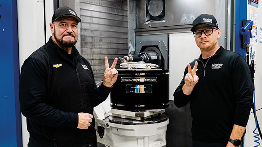
“We now use VNCK every day. It’s been an excellent tool, not just for manufacturing and improving programs, but also as a teaching tool to help us learn the controller.” — Michael Tummond, Engine Engineering Manager, Hendrick Motorsports
Faster, More Powerful Engines
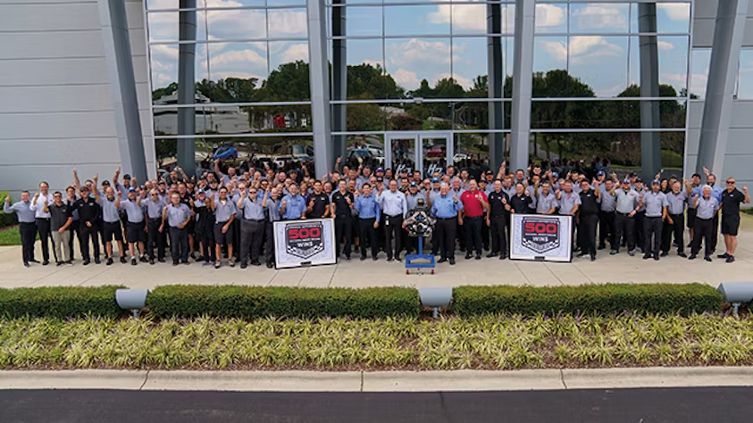
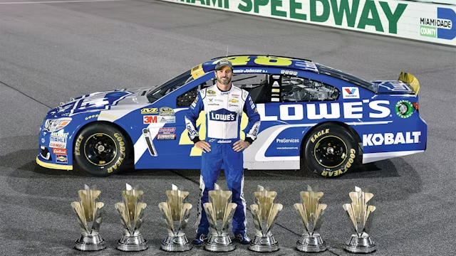
Founded by Rick Hendrick in 1984, Hendrick Motorsports is the most successful team in NASCAR Cup Series history. At the sport’s top level, the organization holds all-time records in every major category: championships, points-paying wins, and laps led. With over 100 team members, its engine department supports more than 500 racing events per year, supplying horsepower for teams in both the Xfinity Series and the top-tier Cup Series. Hendrick engines have powered more than 500 wins across NASCAR’s three national touring series.
In a sport where performance relies heavily on engine power, having efficient, powerful, and durable engines is non-negotiable. That means embracing cutting-edge technology and constantly finding innovative ways to stay ahead of the pack.
Driving Innovation with Siemens and Swoosh Technologies
To stay at the forefront of engine innovation, Hendrick Motorsports partnered with Swoosh Technologies—a Siemens Digital Industries Software partner—and adopted NX™ and VNCK (Virtual Numerical Control Kernel), both part of the Siemens Xcelerator portfolio of software, hardware, and services.
Prioritizing Accuracy and Repeatability
The team’s goal was clear: build better engines. But they had reached the limits of their old equipment and needed more accurate and repeatable results. After a careful evaluation, they invested in higher-precision machines equipped with Siemens controllers.
“We’ve always been a Siemens-driven company,” explains Tummond. “All of our product lifecycle management runs through Siemens software, but we’d never used Siemens numerical controllers for manufacturing. This was our first time, so we reached out to Swoosh Technologies for support.”
The Value of the Digital Twin
Once the new equipment was in place, a new challenge emerged: learning how to use it. With support from Swoosh and Siemens, the team quickly got up to speed and discovered how VNCK and the digital twin could help them improve part production.
“All of our product data was already managed through Siemens software, but it stopped there. We used Siemens for programming, but now that our machines run Siemens controllers, the integration and connectivity between the two has been great,” says Tummond.
A More Efficient Engine Design Process
Along with the new machines, Hendrick Motorsports invested in a machine simulation kit and postprocessor to bring everything together.
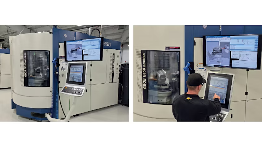
“The one piece of software I took a gamble on was VNCK. At first, I thought it just gave digital readouts from the desktop—which would be useful for training—but it turned out to be a full-blown digital twin.”
With VNCK, the team can analyze any machine parameter directly from their desks, revolutionizing how they program and simulate.
“VNCK allows us to write and test programs away from the machine. Programming itself might be simple, but the tolerances we’re chasing are incredibly tight. VNCK lets us prove part alignment before we make any cuts.”
Standout Results:
Zero scrap rate thanks to pre-validation with simulation.
10x improvement in precision, achieving ten-thousandths of an inch vs. thousandths.
50% reduction in setup time, cutting engine block setup from one hour to just minutes.
Faster diagnosis of errors in production.
Full simulation of all processes—moving beyond basic toolpath verification in NX.
A New Simulation-First Culture
Before this shift, the engine department didn’t use simulation in manufacturing. Today, everything is simulated.
“We weren’t taking advantage of the digital twin or even machine simulation before—just the out-of-the-box toolpath verification in NX. Now, with these Siemens solutions, we’re more confident in our programming, especially as our part alignments grow more complex,” says Tummond.
Thanks to NX, VNCK, and Siemens controllers, Hendrick Motorsports has reached a new level of precision.
“We used to be happy with a few thousandths of an inch. Now, we’re working with ten-thousandths. We’ve improved our accuracy tenfold.”
Racing Toward the Future
Currently, only 3 out of 50 machines on the Hendrick Motorsports campus have VNCK capabilities. Looking ahead, the team plans to expand its use of digital twin technology and bring more high-precision machines into their workflow.
“We need to flip the script. This experience has opened our eyes to what’s possible—and what we need to build faster race cars,” concludes Tummond.
Curious about how simulation and digital twins can transform your manufacturing process? Discover what Siemens and its partners can do for your team.
In an era of digital transformation, companies are seeking engineers who are not only technically proficient but also fluent in the digital tools that are reshaping the manufacturing industry. Graz University of Technology (TU Graz) in Austria is responding to this challenge by equipping students with hands-on experience in model-based design, simulation, automation, and closed-loop manufacturing — all powered by Siemens Xcelerator.
A Modern Education for a Digital Industry
At TU Graz, the Faculty of Mechanical Engineering and Economic Sciences combines mechanical engineering with business insight to educate future-ready professionals. As Dr. Franz Haas, Dean of the faculty, explains:
“Our mission is to develop innovative, interdisciplinary, and holistic solutions for the full lifecycle of products in automotive, energy, and production engineering.”
From the first semesters of the bachelor’s degree through master’s and doctoral programs, TU Graz students are immersed in computer-aided engineering tools and digital workflows. Through the Siemens Xcelerator platform — which includes software, hardware, and services — they gain early access to the same technologies used in cutting-edge global industries.
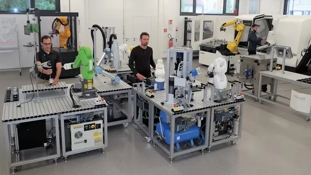
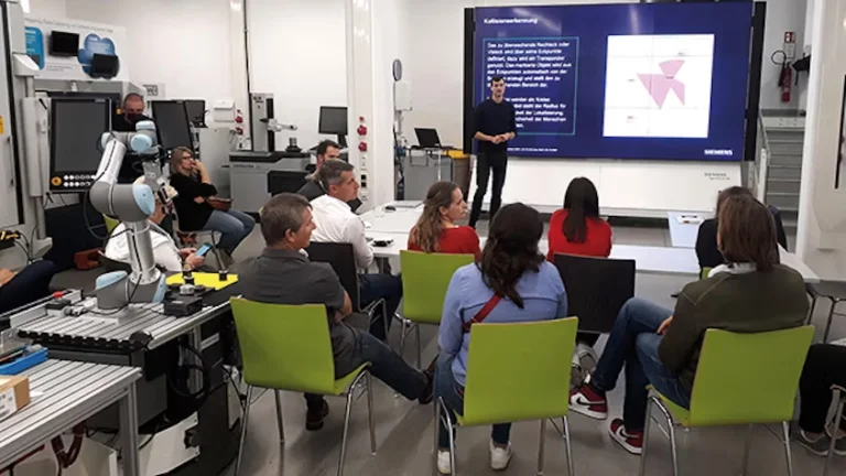
The smartfactory@tugraz: A Living Lab
At the heart of TU Graz’s innovation ecosystem is the smartfactory@tugraz, a learning and research facility designed to explore and demonstrate agile, autonomous, and digital production. It’s part of the Smart Production Graz initiative and offers:
Real-time production line reconfiguration
Integration of robotics and additive manufacturing
A private 5G network to support industrial IoT
A safe space for companies to test new manufacturing approaches
This environment allows students, researchers, and partners to experiment with advanced concepts — from automated tool transport using mobile manipulators to full-scale digital twin applications.
Software-Based Manufacturing in Action
In the smart factory, students use Siemens Digital Industries Software to explore a fully connected product development and manufacturing process. They apply:
NX™ for CAD/CAM
Teamcenter® for PLM
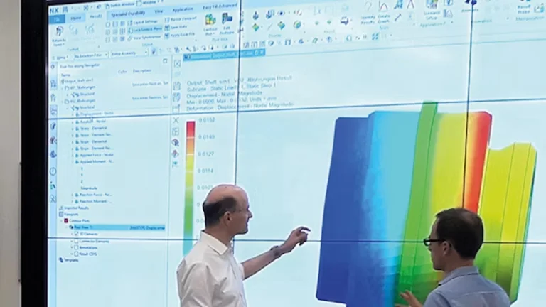
Simcenter™ Nastran for structural simulation
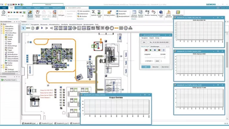
Tecnomatix® for digital manufacturing and robotics simulation
With this software suite, they can design, simulate, and optimize production processes long before physical implementation. They also use virtual commissioning to test PLCs and automation systems digitally, reducing real-world commissioning time and safety risks.
Closed-Loop Manufacturing and Vertical Integration
Thanks to full data consistency from design to execution, TU Graz students experience true closed-loop manufacturing. Updates made by machine operators in the factory are automatically sent back to the digital design environment via Teamcenter and NX Open, allowing for continuous optimization.
Key advantages include:
Real-time location tracking of mobile assets
Predictive maintenance using machine data
Tool digitization via laser scanning and integration into NX CAM
A connected tool database using Teamcenter X Resource Management
Additionally, the university links its smart factory with other academic pilot factories in Austria using Insights Hub, creating a virtual network of collaborative innovation.
A Model for the Factories of the Future
At TU Graz, future engineers gain practical knowledge that often surpasses what’s currently implemented in industry. With support from Siemens and a full suite of Xcelerator tools, they are trained to think holistically, work sustainably, and lead digital manufacturing initiatives with confidence.
“Siemens software covers the entire product lifecycle, which is key to closed-loop manufacturing,” says Dr. Rudolf Pichler, Head of smartfactory@tugraz. “Using Siemens Xcelerator helps us educate broad-minded and skilled creators of tomorrow’s products and systems.”
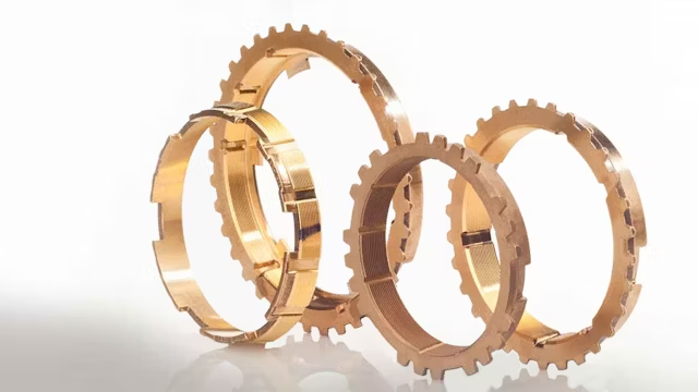
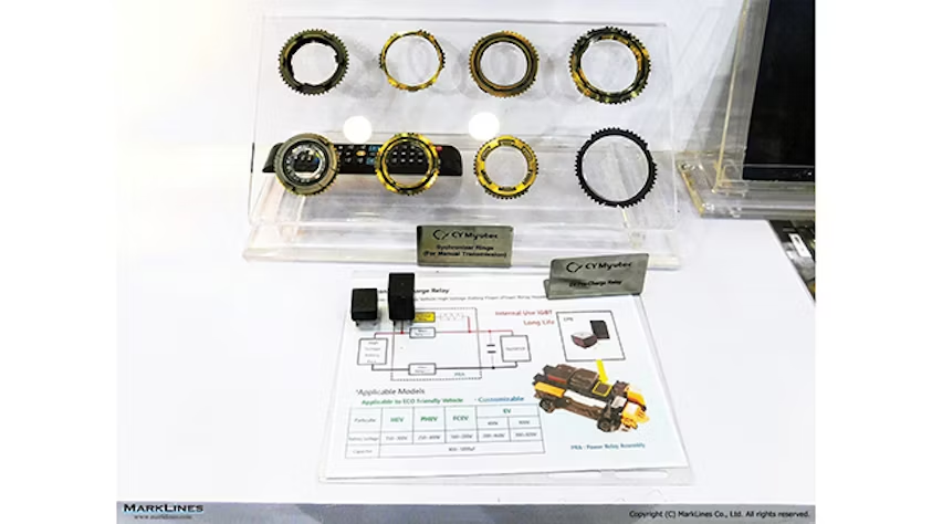
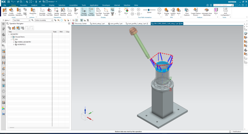
How NX CAD/CAM revolutionized synchronizer ring manufacturing
The Client
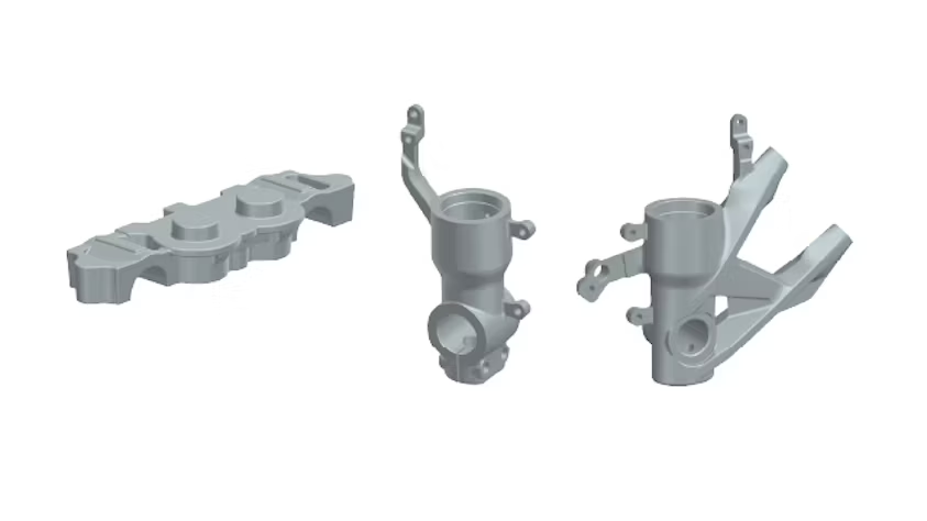
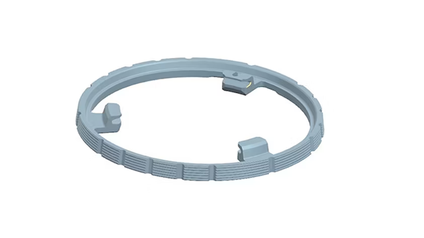
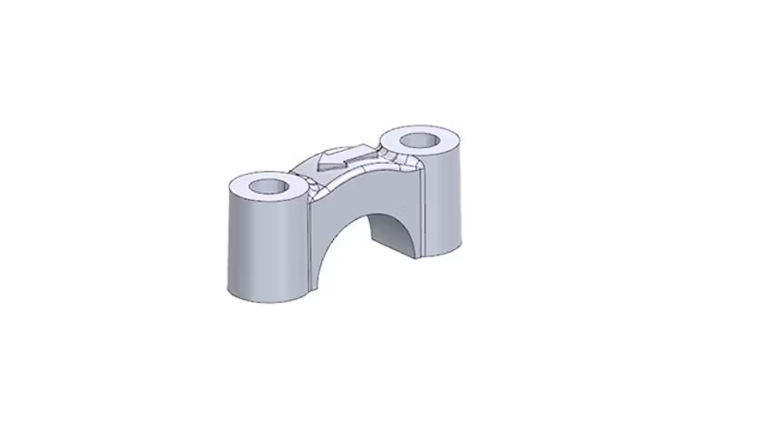
ANAND CY Myutex Automotive (ACYM) is a specialized manufacturer of synchronizer rings for the automotive industry. These components are essential in synchromesh gearboxes, advanced transmission systems that enable smooth gear changes in passenger and commercial vehicles.
The Challenge
ACYM faced multiple obstacles that limited their responsiveness and competitiveness:
Technical Issues:
Design and production teams working in silos
Outdated CAD software without collaborative capabilities
Incompatibility with client file formats
Imprecise generation of complex surfaces
High manufacturing error risks
Business Impact:
Extended development cycles
Delayed customer deliveries
Risk of costly machinery collisions
Loss of competitiveness in an expanding market
“With original equipment manufacturers focusing on high-performance vehicles and expanding electric vehicle offerings, the demand for advanced transmission solutions is increasing” – Pranav Rawal, General Manager at ACYM
The Solution: NX CAD/CAM
In collaboration with DDSPLM (Siemens Digital Industries Software partner), ACYM implemented NX™ software, part of the Siemens Xcelerator business platform.
Key Implemented Features:
Synchronous Technology: Parameter adjustment without historical data
CAD/CAM Integration: Single source of truth for the entire process
Advanced Automation: Customizable tools for toolpath creation
Universal Compatibility: Support for multiple file formats
Integrated Simulation: NC program verification without damage risk
Quantifiable Benefits
Operational Efficiency:
40% reduction in design and production times
40% reduction in concept-to-delivery time
30% savings in operational costs
Technical Improvements:
Elimination of manual transfer errors
Greater precision in complex surfaces
Better machining process control
Significant reduction in material costs
Enhanced Collaboration:
Design and production teams working in an integrated manner
Smooth communication with international clients
Complete version control and traceability
Client Testimonial
“The synchronous technology in NX is particularly beneficial for working with imported data. It allows us to adjust hole sizes or shift surfaces on models without historical data. The same way our synchronizer rings deliver a smooth gearbox experience, using NX synchronous technology provides us the flexibility to quickly adjust parameters and implement design changes as needed.”
Pranav Rawal, General Manager, ANAND CY Myutex Automotive
Key Lessons
Integration is fundamental: Eliminating silos between design and manufacturing generates exponential efficiencies
Technical flexibility matters: The ability to work with diverse data is crucial in global supply chains
Measurable ROI: Efficiency improvements translate directly into competitive advantages
Scalability: Solutions must grow with market demands
Why this case matters
In a constantly evolving automotive market, where electrification and efficiency are priorities, ACYM demonstrated that digital transformation is not just an option, but a strategic necessity.
Is your company facing similar manufacturing challenges? At Goaltech, we help companies identify and implement the technological solutions that transform their operations.
Contact our team to explore how we can accelerate your digital transformation.
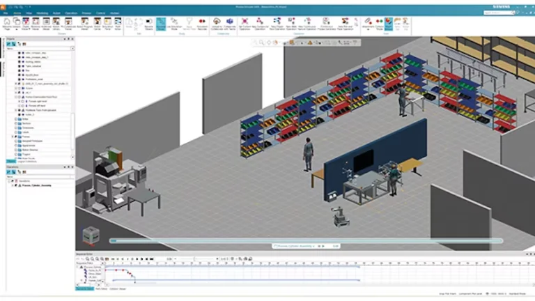
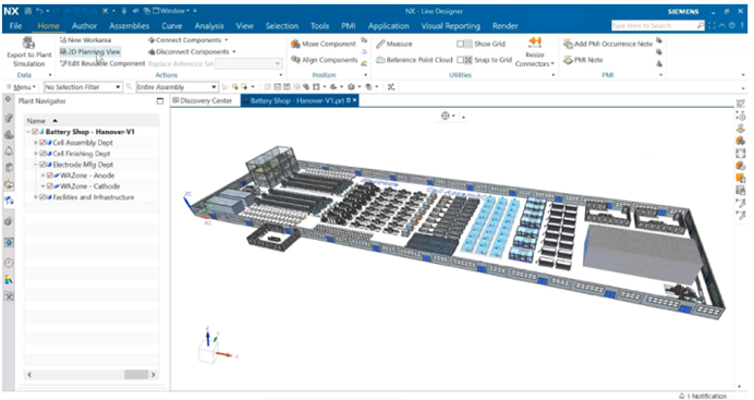
The rapid development of the new energy sector presents battery manufacturers with dual challenges: expanding production capacity while adapting to fast-evolving technology. Traditional 2D factory planning models no longer align with smart manufacturing requirements. However, Siemens Industrial Software’s innovative Line Designer solution is breaking new ground by leveraging 3D digital technology, redefining efficiency and accuracy in battery plant construction.
Line Designer 3D Super Battery Plant
3D digital factory planning: A game-changer
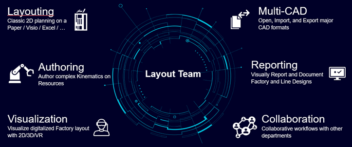
At the core of 3D digital factory planning is its full-process visualization and dynamic optimization capabilities. Siemens’ Line Designer utilizes parametric modeling technology, allowing engineers to seamlessly complete equipment layout, logistics path planning, data analysis, and report generation—all within a virtual environment. This advanced approach improves efficiency by over 40% compared to conventional 2D methods.
Line Designer core function
The system’s extensive intelligent library contains thousands of 3D models covering industrial equipment, building structures, and other key assets. It also supports multi-format data imports, including CAD and point clouds, making it ideal for complex renovation projects where flexibility and precision are critical.
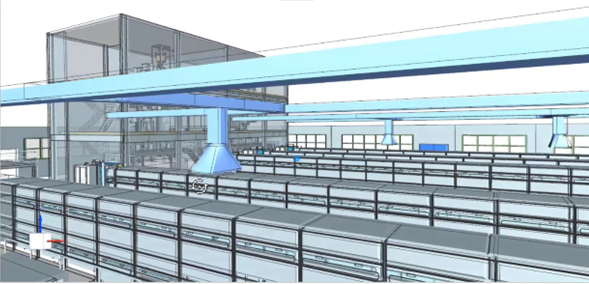
Real-world impact: A 6GW super battery plant
In a landmark 6GW battery manufacturing facility project, Siemens’ technical team harnessed Line Designer to achieve rapid, one-click conversion from 2D floor plans to 3D digital models. The software’s dynamic interference checking feature played a pivotal role in identifying and resolving spatial conflicts between production equipment and utility pipelines early in the design phase. This proactive approach significantly reduced potential rework costs, streamlining the overall construction process.
Collision checks of 3D environment in Line Designer
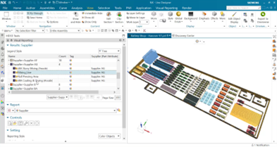
Moreover, Line Designer’s intelligent visualization system generates automated data dashboards that categorize information by supplier performance, equipment status, and other critical metrics. These insights empower procurement and engineering teams to make informed decisions, enhancing operational efficiency.
Report and collaboration in Line Designer
Streamlining Collaboration and Design Integrity
Engineers can rapidly complete 3D factory layouts by simply dragging pre-engineered models from the library onto 2D floor plans,” explained a project engineer using Line Designer. “The software also ensures seamless conversion of 3D models back into 2D blueprints through reference set switching, preserving full design integrity with a single click.”
A representative from Siemens Industrial Software further emphasized the transformative potential of this approach:
Our goal is to make factory planning as simple and efficient as building blocks. By integrating immersive interactive environments and kinematic simulation capabilities, customers can not only validate design plans intuitively but also pre-rehearse production processes in a virtual space, proactively mitigating potential risks.”
The future of smart manufacturing
As the new energy industry shifts toward intelligence and sustainability, 3D digital factory planning is emerging as an industry standard. Siemens Industrial Software remains at the forefront of this evolution, driving digital transformation in manufacturing through its deep expertise in industrial software solutions.
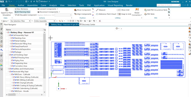
One click converting from 3D models back to 2D blueprints
With cutting-edge tools like Line Designer, Siemens continues to enable manufacturers to optimize efficiency, reduce costs, and build smarter, future-ready factories. The 6GW super battery plant is just the beginning—ushering in a new era of intelligent industrial design and execution.
6GW super battery plant in NX Line Designer
Benefits of Using Siemens NX Line Designer for Battery Plant Planning
Siemens NX Line Designer provides a transformative approach to battery plant planning through advanced 3D digital modeling. One of its key benefits is efficiency—engineers can achieve over 40% faster design completion compared to traditional 2D methods. The software’s parametric modeling capabilities enable seamless equipment layout, logistics path planning, and real-time data analysis within a virtual environment.
The tool’s intelligent library, containing thousands of pre-engineered 3D models, allows for accurate and rapid assembly of factory layouts. This feature supports multi-format data imports, including CAD and point clouds, making it particularly valuable for complex renovation projects. Additionally, the dynamic interference checking function proactively identifies and resolves spatial conflicts between equipment and infrastructure, significantly reducing costly rework during construction.
Another major advantage is enhanced collaboration. Engineers can convert 2D floor plans into fully functional 3D environments with a single click, facilitating seamless integration between different teams. The system also generates automated data dashboards, offering real-time insights into supplier performance and equipment status.
By integrating kinematic simulations and immersive virtual environments, Line Designer allows manufacturers to pre-rehearse pro
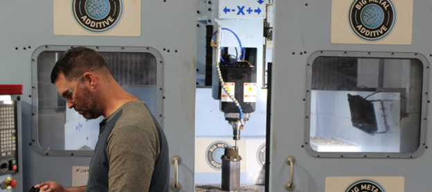
This blog series explores key lessons from my visit to Big Metal Additive (BMA), an advanced manufacturing shop in Denver, Colorado, that integrates Siemens NX for Manufacturing software and hardware for hybrid machining. This methodology, which combines additive and subtractive processes, enables the production of parts once considered impossible. However, mastering this workflow requires a hybrid skill set, where employees must efficiently operate diverse machinery and software. In this blog, we will delve into the essential skills and key machining trends in the industry.
Big Metal Additive: Innovation in Additive Manufacturing
I recently visited a leading industrial additive manufacturing customer, Big Metal Additive (BMA), which uses Siemens Additive Manufacturing software. BMA is a specialized metal 3D printing shop that integrates welders with 5-axis CNC mills to explore new frontiers in manufacturing. Their work often pushes boundaries, serving both private companies and government agencies to replace traditional processes, build intricate geometries, and conduct material testing.
The Growing Need for Hybrid Skills
A few months before visiting BMA, I spoke at a technical education conference, emphasizing the need for educational institutions to adapt their training programs to modern manufacturing. I reinforced that companies should break down silos and train employees across multiple disciplines—machining, welding, and toolmaking—especially as technologies like additive manufacturing, robotics, and automation become more prevalent.
BMA exemplifies this shift. It is not just a machine shop—it is a hybrid manufacturing powerhouse that embraces cross-functional expertise.
The Power of Hybrid Machining
Hybrid machining integrates additive and subtractive processes, allowing manufacturers to reinvent production workflows. While 3D printing has advanced significantly, it still cannot fully replace traditional methods. However, combining it with milling or turning enhances efficiency and expands design possibilities.
From a workforce perspective, this requires more than just welders, machinists, and programmers—it demands multi-skilled employees who can adapt to different tools and equipment. The future belongs to versatile engineers who can operate across domains.
CNC Meets Robotics: A Powerful Combination
BMA’s shop floor is a fusion of technology, featuring both 5-axis CNC machines and articulated robots capable of welding and machining. Engineers must navigate G-code-driven CNC machines alongside six-axis robotic systems with SINUMERIK controls—each with vastly different programming languages and degrees of freedom.
One engineer at BMA was hired for his CNC background but was tasked with learning robotics from day one. He embraced the challenge and is now an expert in both fields—a testament to the adaptability required in modern manufacturing.
Software as the Driving Force
BMA’s hybrid operations rely on multi-functional CAM software. Siemens NX Multi-Axis Deposition enables programmers to create both additive and subtractive toolpaths within a single environment. This means engineers must understand both processes and synchronize them for successful builds—a critical step in creating a digital twin for hybrid machining.
At BMA, welding expertise is not limited to hands-on operations—it starts in the software. Engineers like Jordan factor in heat dynamics while programming additive toolpaths. Miscalculations in layer height can disrupt a build, but experienced engineers adjust settings in NX for Manufacturing to ensure success.
BMA does not rely on intuition alone. Engineers meticulously record process data, tracking voltage, amperage, and temperature during builds. This data is stored in a database, allowing for process optimization and repeatability. Many BMA customers seek to explore additive manufacturing’s potential—whether to create complex geometries, reduce lead times, or supplement production. Each project involves extensive testing, often requiring destructive analysis like tensile strength testing. Even tasks like wire EDM cutting—traditionally handled by specialists—are now done by multi-skilled engineers.
The rise of hybrid machining raises fundamental questions about workforce training. Should technical schools restructure their programs toward certification-based models that cover a wider range of skills? Should degree programs become more flexible, allowing students to mix and match courses across disciplines? Education must evolve sooner rather than later.
The Future of Hybrid Manufacturing
BMA’s engineers embody the versatile workforce of the future. Their ability to blend skills across machining, robotics, and data analysis creates a dynamic, resilient manufacturing environment.
As additive manufacturing continues to evolve, shops like BMA will shape the next era of production. I can’t wait to see what they achieve next. Stay tuned for my next blog, where I will continue exploring the future of hybrid manufacturing and industry trends.
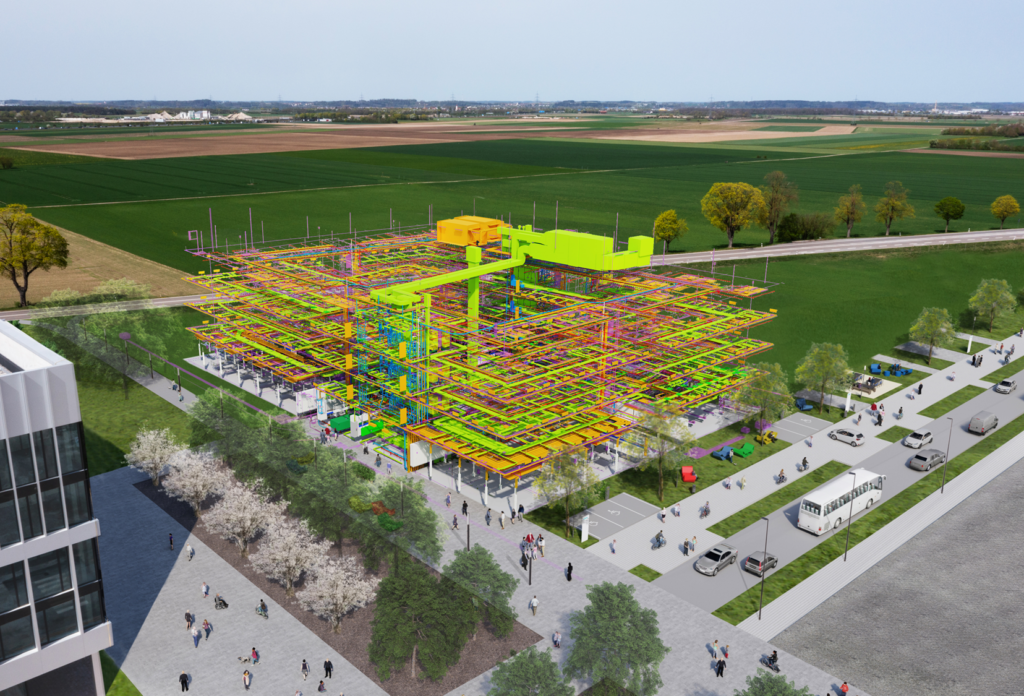
Product: NX Design Industry: Construction and Manufacturing
The integration of Building Information Modeling (BIM) with NX is transforming the way industrial plants and factories are designed. By combining the strengths of both tools, Siemens Real Estate and Siemens Digital Industries Software are streamlining workflows, improving collaboration, and enhancing efficiency in shop floor planning.
BIM and NX: A Powerful Collaboration
Siemens Real Estate (SRE), a global leader in corporate real estate management, is at the forefront of digitalization and innovation. With a “digital-first” approach, SRE mandates the use of BIM for all new construction projects. This methodology enables the seamless connection between the physical and digital worlds, laying the foundation for a digital twin of buildings and shop floors.
A prime example is the Digital Native Factory in Nanjing, which was fully planned and simulated using digital twin technology. By integrating factory data, shop floor layouts, and building performance data, SRE created a comprehensive digital representation of the facility. This success highlighted the need for more efficient processes to scale projects and integrate multiple teams.
Bridging the Gap Between BIM and CAD
Typically, BIM and mechanical CAD are managed by separate teams. BIM data, owned by Siemens Real Estate, is used to design buildings, while shop floor layouts are planned by engineers. The traditional workflow involves:
Creating and updating BIM models in dedicated software.
Importing BIM data into NX for shop floor planning.
Revising and exporting design changes via IFC format to ensure updates are reflected in both environments.
Since design reviews occur frequently, this process demands constant data transfers between architects and engineers, increasing complexity and the risk of errors.
Challenges in BIM and CAD Integration
The manual process of exporting and importing data presents major challenges, including:
Data Format Differences: BIM data is stored in single part files, while NX structures data as assemblies and components.
Positioning Issues: BIM relies on a consistent coordinate system, which must align with NX models.
Complexity in Data Translation: Converting large-scale BIM models into NX can be time-consuming, requiring hours of processing and generating thousands of parts.
To address these challenges, Siemens Real Estate collaborated with Siemens Digital Industries Software to develop better BIM data import solutions in NX. These solutions include preserving BIM structures, simplifying file conversions, and improving IFC translation to reduce errors and enhance usability.
The Future of BIM and NX Collaboration
Looking ahead, Siemens is working on real-time design updates between BIM and NX, reducing the need for manual transfers. The goal is to create a seamless, interconnected workflow, where engineers receive automatic alerts when changes occur.
Additionally, VR and Immersive Engineering are becoming integral to design collaboration. Siemens is exploring Sony’s XR head-mounted displays and the Industrial Metaverse to enhance shop floor planning and virtual decision-making.
Another significant advancement is the NX Translator for Revit, introduced in June 2024. This tool, available via token licensing, enables the direct recognition of identical components (e.g., doors, beams, windows), streamlining BIM data import into NX.
Ultimately, Siemens aims to develop a single source of truth for BIM and CAD data, eliminating inefficiencies and enabling fully digitalized, automated workflows. By continuing to innovate, Siemens Real Estate and Siemens Digital Industries Software are shaping the future of integrated industrial design.
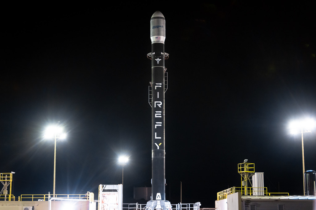
Morgan and Drew from Firefly Aerospace take us behind the scenes of their design process—from whiteboard sketches to fully engineered rockets. Learn how they leverage advanced tools like Siemens’ NX and Teamcenter to iterate quickly and bring complex structures to life.
They also reveal their thoughts on the role of AI in aerospace engineering, the significance of sustainability in rocket development, and the push for reusable rockets to lower costs and minimize environmental impact. The engineers also share insights on the future of space travel, the challenges of scaling rocket designs, and how the private space sector is driving a new era of exploration.
What you’ll learn about in this episode:
What is Firefly Aerospace?
Firefly Aerospace is a Texas-based private aerospace company founded in 2017 focusing on providing end-to-end space transportation services. Firefly is on a mission to enable our world to launch, land and operate in space, anywhere, anytime. They specialize in launch vehicles and spacecraft.
The design process at Firefly Aerospace
Drew, Morgan and Greg begin discussing the design process at Firefly Aerospace and how they get from concept to launch. They start with a goal or problem statement at a whiteboard discussion and then begin making early sketches. With the necessary stakeholders, they determine boundary conditions, constraints, what materials are available and what the budget is. From then, they begin creating a preliminary CAD model. They emphasize their iterative design process, so they iterate on and refine the CAD model through discussions, meetings and design reviews.
Morgan notes that sometimes the iterative process is physical and sometimes it is digital on the CAD models, running simulations and analyses virtually. But eventually, the iterations will come into the physical world for real-life validation of the design. The design touches different teams and design trades throughout the process to ensure it is up to regulations, standards and requirements.
CAD software and Siemens’ NX in aerospace design
Greg then Morgan and Drew about the benefits they see using CAD, specifically NX CAD software from Siemens Digital Industries Software. Morgan discusses how it’s nice to be able to “fly around in 3D space” and actually look at a design on the screen. You can make updates quickly, share easily with Teamcenter to get a visual representation and fully see the entirety and fullness of a design in CAD software.
Drew mentions structures as an area where visualization is especially helpful to note clearances with other components and knowing something will work when it’s manufactured. Morgan also adds that you can “virtually cut something in half to look at a joint.”
Rockets require very complex assemblies, but with NX, that design complexity is simplified. They mention how load settings such as how loading only one part of an assembly can speed up the design or review process, as well as how NX helps with being able to create structures with a “sandwich laminate,” as their previous software didn’t allow individual parts to have dissimilar materials. “With NX, it’s fully streamlined. It’s easier to do those kind of parts,” Drew says.
Before moving on, Drew also notes how helpful and useful advanced features in NX such as Synchronous Modeling are. “To be able to just do that on the fly without fully rebuilding the model, it’s so useful,” he says.
Challenges in the design process at Firefly Aerospace
We then move on to talk about challenges in the day-to-day design process working in the aerospace industry at Firefly. Morgan first mentions how regulations and the general rapid pacing of the industry can be a challenge, “It’s incredibly competitive. It’s like running on a treadmill. You have to always be innovating, always be iterating, testing, and doing better so that you are still a competitor in the industry,” she says.
Drew then mentions that the iterative process itself is a challenge, especially if it is something they haven’t done before so they can’t apply lessons from previous experiences. There is a lot of trial and error in the design process. Morgan and Drew discuss a specific example with scaling their flight-proven 6-feet-diameter Alpha rocket to a medium-class launch vehicle that is 14 feet in diameter. Throughout the process, they are learning new lessons as they create a bigger rocket.
They mention that one thing that does help them face challenges easier though is collaboration with Teamcenter. Everyone at Firefly has access to view CAD files and drawings so can reference anything needed during a design review concurrently, whether they’re in the Cedar Park office or at the different test sites.
The future of sustainability in aerospace design and engineering
We then move on to talk about trends in the industry, beginning with sustainability. Morgan notes how important sustainability and especially reusability is in their field, as not only does it help from an environmental standpoint but it enables cost savings as they don’t need to start from the ground up every time. They save on labor costs as well as reduce lead times for materials the pain points that come along with creating something completely new. Both Morgan and Drew also add that Firefly is focused on composites and lightweighting with carbon fiber structures.
“Pioneering carbon fiber structures. That’s been Firefly’s main selling point—a fully composite rocket. So, lighter materials, better-performing rockets,” Drew says. Morgan adds, “When you have lighter structures, you can lift either more propellant or more payload.”
Morgan also discusses how designing for reusability evolves over time as a young aerospace company. When they first start out, they’re focusing on being flight-proven and less on reusability. When they are more established, they can pivot towards reusability if it’s economically viable. The three then talk about what recovery and reusability actually looks like in practice, including calculating where the rocket will splash back down.
The future role of the Industrial Metaverse and Immersive Engineering in rocket design
Continuing the talk on trends, Greg briefly explains the Industrial Metaverse and Immersive Engineering and asks if Firefly would benefit from leveraging immersive tools. Drew thinks immersive technology would be especially beneficial for integration and production planning. Morgan agrees with the benefits within manufacturing and production planning, and also thinks the integration of AR and VR into training could be incredibly valuable. Though they haven’t explored it yet, Morgan says, “We haven’t dipped our toes into that realm yet. I think it’s a technology that is very promising and has a lot of room to grow in this industry, and Firefly could absolutely make use of it in the future.”
Morgan adds how helpful immersive technology could be in manufacturing with mitigating issues that arise in non-conformance reports. For example, showing a circle where a bolt hole is meant to be if someone is a few degrees off during manufacturing.
Greg also asks if they would find value specifically in the Sony XR head-mounted display and NX Immersive Designer, with visualizing massive structures like rockets in an immersive environment. Drew says that an immersive experience would be really helpful with seeing models in real-time scale and space, visualizing sizes of parts and getting a sense of scale. With some parts being absolutely massive, they want to know if a crane would be needed, if multiple people would be needed to move it or if there is clearance to get inside the space to install a part before getting to the manufacturing stage. Morgan tells a story about discovering a part in real-life being much bigger than it’s on-screen digital counterpart, “Sometimes you do lose that sense of scale when you’re sitting behind a desk,” she says. “If I had the ability to slap on some glasses or a headset and be able to walk around the rocket at scale, that would be incredibly useful.”
How does Firefly Aerospace use AI in the design process?
Moving onto the last trend of the episode, we discuss AI and how/if Firefly is using it throughout their design process. Drew says that while they have experimented with generative design, improvements are necessary for it to be incredibly useful for their design process. He cites an example of generative design technology creating a “cool and optimized” part, but it could not take into account manufacturability, integration into the full assembly, or cost/budget into its design. However, he believes that as AI grows and gets more capable, it will be a very useful tool for engineering. “Maybe just to do a quick trade study for a particular design, where you can give it a prompt, and it can create a quick concept design that you can refine from there. Less so just a one-and-done and makes-it-for-you solution,” he says, then concluding how AI will evolve and get better and he looks forward to the improvements that will be made over time.
Though Morgan also believes that AI is powerful and has come a long way in a short amount of time, she says “I think there’s still something inherently human in a lot of the engineering that you do…there are engineering decisions and judgments that humans make. Something imperfect is purposely included because the design is, therefore, more human, more manufacturable, or more usable.” So while she doesn’t see AI doing the design work any time soon, she does think that AI could take over a lot of automation like in math, analysis processes and design edits.
Check out our previous episode recap of our AI episode, AI-Enabled CAD: Enhancing Design Efficiency with Siemens’ NX, to learn about some of the AI-enabled capabilities in NX that help engineers to be more productive and reduce inefficiencies. Similar to Drew’s wish of giving a prompt to the software, we also recently introduced NX Copilot, powered by Microsoft Azure.
What does the future of design look like to Firefly Aerospace?
Morgan says the next generation of engineers will continue to build with AI and new features and technology that come out, such as Immersive. For herself, she hopes to be like Tony Stark— seeing holograms of a rocket and updating it with a wave of a hand or voice command.
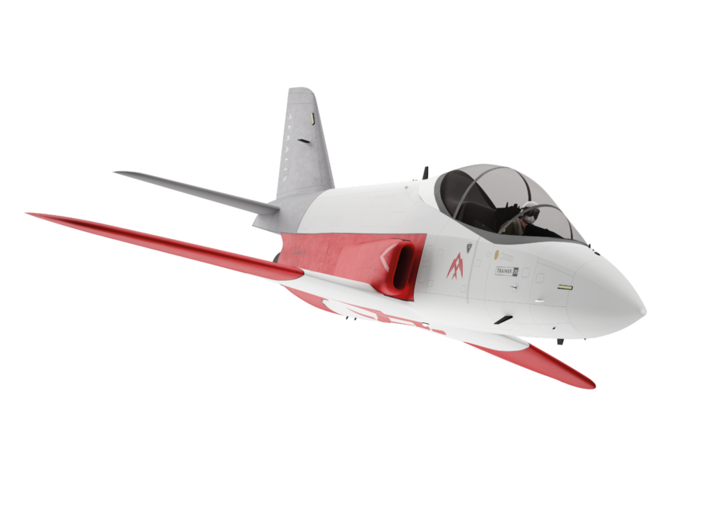
AERALIS is a digital enterprise that leverages digital engineering and a digital thread in accordance to AERSIDE: AERALIS Smart Integrated Digital Enterprise. As requirements and technology changes in the aerospace industry, it is absolutely needed to be a digital enterprise. Charlie says, “Aircraft are designed about 20 years before they land on the market in some cases, and by that point, the requirements and technology have completely changed. So, there’s a real push to keep up with that change and reduce the period from ideation to launch.”
Charlie defines digital engineering as “the application of digital processes throughout the entire lifecycle of a system, from concept to manufacture, operation, certification and disposal, but all connected via a single source of truth.” At AERALIS, the entire lifecycle of the aircraft is digitally developed, connected by a single source of truth. Callum says this digital engineering enables efficiency, collaboration and innovation.
With a digital thread, they can design parts based on known requirements, and anyone can see and be notified of changes to requirements or parts themselves. Callum again emphasizes how a digital thread enables efficiency. With everything being digital-first, Charlie notes that AERALIS can easily collaborate in a live design environment with other designers or manufacturers. From simulation and optimization to manufacturing and real world operations, everything is linked together along the digital thread with digital twins.
Model-Based System Engineering (MBSE) at AERALIS
AERALIS adopts the Model-Based Systems Engineering Arcadia Method. Callum explains how they are “breaking down a problem at an operational level and then going into more detail at functional, logical and physical levels.” With this MBSE approach, they are not just using it on the aircraft but to all business operations as a whole. Charlie uses the comparison of just how computer-aided design (CAD) evolved and became a digital step in design as opposed to drawings on paper, MBSE is the development of digital models instead of just documents and drawings.
AERALIS works closely with Siemens with our professional services implementation team. AERALIS engages in agile collaborative feedback with Siemens daily, including identifying new capabilities that they need or trialing different capabilities and methodologies. “Every week, we’re designing something, building it, testing it, changing it a bit more, and working in that real agile sprint,” Charlie says regarding testing new capabilities they request. This workflow of close collaboration helps them launch, deploy and adopt new functionality amongst their engineers quickly.
How AERALIS uses NX to solve challenges
Callum notes that AERALIS has a managed NX environment, where everything in NX is integrated with Teamcenter PLM software to enable collaboration with design partners such as Hamble Aerostructures. With NX and Teamcenter, both design teams located in Bristol and Southampton can work together on the same live digital models with the same requirements. With NX and Teamcenter, they can leverage a full digital thread— “It is a thread and collaboration and efficiency and working on the same stuff. It’s not emails.”
Charlie and Callum also call out specific benefits they realize with NX, such as including maintainability in their aircraft from day one. NX also includes human models, so they can test their designs and make sure anyone from the largest man to the shortest woman can access all parts of the aircraft needed to fly. “You can mock the view of a pilot from their eyes, and you can move their head up and down, and you’ll be able to see what they see in the cockpit. So, you can map out the anthropometrics,” Charlie says.
The design process at AERALIS
Callum briefly explains the design process at AERALIS, stating that it operates as a “thin prime.” They are modular in their organization and design by a requirements-driven approach. They collaborate with Hamble Aerostructures for some of the design and manufacturing including the Common Core fuselage, and other design firms for system design. With multiple companies, they still design as “one team” as a digital enterprise.
Aerospace industry challenges
Charlie and Callum then describe some of the challenges being seen in the aerospace industry and how AERALIS is responding to them. Charlie notes that aircraft systems have more complexity, take longer to develop, need more resources and require a bigger industrial base. Requirements change quickly, and pilots need to train based on those new requirements, but the trainer platforms have to adjust and adapt. He also notes that traditional companies wrestle with legacy IT estates that are not on new technology and not digital. He acknowledges that while AERALIS does not have a legacy IT estate to deal with which allows them to innovate faster, that it also means they are building an organization, processes and toolsets at the same time as trying to build the aircraft itself.
Callum adds on to the challenge of increasing complexity, saying that certification is getting more expensive as complexity and requirements evolve. “I fear that may be reducing the appetite for people to try new things, and limiting how eVTOLs are progressing,” he states.
Greg asks if there are any challenges that are unique to AERALIS, and Charlie mentions that there are not many new aerospace companies in general, but it is especially a challenge as they are trying to do something that has not been done before in the defense industry: modular aircraft. They have to balance the need to get it to market, getting it flying and getting it certified. But they are leveraging partnerships and collaborations with other companies across the UK and the world to solve these challenges.
When it comes to overcoming challenges, Callum says that at AERALIS they start from a theoretical standpoint and ensure that they are future-proofing and having one single source of truth for solutions as they communicate and share data. He shares an example of a challenge they had with part numbering, but states that their “secret sauce” is simply: “Just think about it as a whole— don’t just jump in— and try to build something for the future.”
The future of design at AERALIS
Before closing out the episode, Greg asks about some trends in the industry. They discuss sustainability, noting that sustainability will only increase and leveraging digital tools will allow them to identify more opportunities for optimized and sustainable solutions. The modularity of an AERALIS aircraft is inherently more efficient and sustainable as it is adaptable.
They also address the Industrial Metaverse and Immersive Engineering and look forward to experiencing the benefits of Immersive tools from initial requirements to design to manufacturing. “You can sit on a chair, put a VR headset on, and play around with potential cockpit designs. That’s only possible because we’ve been designing digitally from day one,” Charlie says.
We conclude the episode talking about AERALIS’ ultimate goal of revolutionizing the aerospace industry with modular defense aircraft, how they think the aerospace industry has evolved in their few years as engineers and how it will continue to evolve and their perspective on the general next generation of design.
Product: NX, Simcenter 3D Solutions, Teamcenter Industry: Automotive & transportation
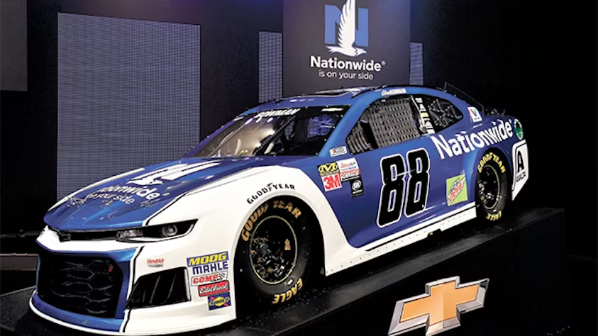
NASCAR Racing Team Leverages Siemens Software for Competitive Edge
Hendrick Motorsports Hendrick Motorsports, a renowned NASCAR® racing team based in Concord, North Carolina, employs Siemens Digital Industries Software solutions—NX, Simcenter, and Teamcenter—to enhance performance and reliability in their racing operations.
Challenges
Design Compliance: Create and test a fleet of cars that meet strict NASCAR regulations.
Data Accessibility: Improve access to data to maximize time spent on analysis and innovation.
Keys to Success
Digital Backbone: Establish a robust infrastructure using Teamcenter.
Collaboration with Siemens: Work closely with Siemens to optimize new tools with each software release.
Comprehensive Software Utilization: Take full advantage of the Siemens software portfolio.
Results
Rapid Development: Quickly develop new parts and assemblies that improve performance.
Design Optimization: Use NX to evaluate multiple options and refine designs.
Efficient Data Mining: Leverage the digital backbone for faster and more reliable access to data.
As Engineering Manager Tad Merriman stated, “If we can take advantage of rule changes faster, we can develop and implement new ideas quicker, leading to race wins. Siemens Digital Industries Software gives us a competitive advantage.”
Hendrick Motorsports has integrated Siemens software since the early 1990s, transforming their operations by streamlining design, simulation, and manufacturing processes. The digital backbone established through Teamcenter enables them to efficiently manage data across various aspects of their racing program.
Conclusion
Hendrick Motorsports continues to demonstrate that leveraging Siemens Digital Industries Software solutions significantly contributes to their success on the track, allowing for rapid innovation and enhanced performance.