


Product: CAM Pro
Industry: Industrial Machinery and Heavy Equipment
DiaCom targets new markets demanding higher levels of technology for its complex molded diaphragms
About six years ago, industrial diaphragm manufacturer, DiaCom Corp. (DiaCom) initiated a shift in its approach to tool design and manufacturing. With a great customer reputation already in place, the time came to upgrade the company’s technologies. The goal: expand into new markets. The Amherst, New Hampshire-based company designs and manufactures innovative, cost-effective molded diaphragms critical to the operation of essential industrial systems and equipment. DiaCom not only produces diaphragms but designs and builds the tooling to manufacture them. The company staffs design and tool departments as part of its business model.

The new technology shifts have allowed entry into new industries requiring more complex diaphragms as well as parallel markets. Those industry targets include aerospace, irrigation, automotive, oil, gas and medical customers. “We wanted to grow dynamically by offering more intricate, cutting-edge products and also expand into new geographic markets in China and Europe,” says Mike Grywalski, manufacturing engineering manager at DiaCom. “There’s more technology demand from these new customers. They don’t just need washers on a garden hose.”
DiaCom customers operate in a different world, with more intricate design demands leaning heavily on parametric modeling to meet government and industry standards. Many of its longtime, established customers now require a similar technological ability to produce more advanced diaphragms.
Expansion required more advanced soft-ware technology. Customers were starting to come to DiaCom with 3D models to work from. The company was using 2D computer-aided design (CAD) software, producing “old-school” drawings that couldn‘t fully define some products. DiaCom recognized the problem and decided to shift its design paradigm.

Grywalski’s shopfloor background helped him realize the need to bring the tool group on board with any CAD technology changes. With many years of CAD and computer-aided manufacturing (CAM) software experience, he recalled compatibility, communication and technical support issues when using software from two different vendors.

“We wanted to bring the tooling group on board with our plans,” says Grywalski. “We wanted to implement CAD and CAM applications from one software company so we could get one-stop support.” The company selected Solid Edge® software for 3D design and Solid Edge CAM Pro software for manufacturing, both from product lifecycle management (PLM) specialist Siemens Digital Industries Software. DiaCom relies on Siemens solution partner Maya HTT for implementation, training and system support.
DiaCom evaluated multiple CAD systems including SOLIDWORKS® software, AutoCAD® software, Inventor® software, Pro/ENGINEER® software and Solid Edge. “While there were many software programs available, we selected Solid Edge because of available support from Maya HTT as well as from Siemens’ Global Technical Access Center organization. This support network paid off well as we initiated changes.” Besides the 24/7 support for both CAD and CAM questions, Maya HTT and Siemens Digital Industries Software helped DiaCom identify postprocessors for its machine tools and solve other hardware/software inter-face challenges.
DiaCom determined that the Siemens Digital Industries Software technology was impressive and pricing was competitive. “Solid Edge gave us the technological capability to design the more complex parts required by existing customers as well as the other new customers we work with,” says Grywalski. “Today‘s changes are often more challenging and can take longer. With 3D, it’s easier to make customer-requested design changes than it was with traditional 2D software.” DiaCom has started to use the synchro-nous technology capability of Solid Edge, applying the simplicity of direct modeling with the control of parametric design. The company continues to evaluate synchro-nous technology as well as traditional ordered design. “In some cases, the ordered approach makes the most sense,” Grywalski says. “At other times, the synchronous approach seems best. Either way, we are seeing a reduction in design time and higher accuracy, both of which have a positive impact on manufacturing. For example, on a recent complex mold project, the use of Solid Edge modeling was 25 to 30 percent faster than traditional 2D design and was more accurate.”

Making modifications to existing diaphragm designs is quite common at DiaCom. By using synchronous technology instead of traditional history-based processes, DiaCom has experienced a reduction in revision time by up to 50 percent on recent design work.
DiaCom is designing programs to create automated part and tool models based on variable tables in Solid Edge. By applying new business engineering processes, these programs are being used by designers to accelerate design without sacrificing accuracy. Though this is in the early stages of development, the company has already experienced significant benefits with the new approach.
For its computer numerical control (CNC) programming tool, DiaCom selected Solid Edge Cam Pro from Siemens Digital Industries Software. DiaCom uses Solid Edge Cam Pro to program its Okuma CNC lathe and Fadal CNC mill, among other pieces of equipment to machine the compression molds that are used to manufacture the diaphragms. DiaCom’s tool room lead pioneered the use of Solid Edge Cam Pro to program the machine tools. Additionally, the mill and lathe machine operators have been trained in the use of Solid Edge Cam Pro to program the machine tools.
“With 3D CAD in place, we have been designing some pretty complex parts for various applications. Many customers prefer not to use traditional diaphragm designs,” Grywalski says. The more sophisticated designs also required Solid Edge CAM Pro 3-axis machine milling and turning programming capabilities.

The combination of Solid Edge and Solid Edge Cam Pro has provided “a seamless transfer of tool design communication between our design group and the shop floor,” says Grywalski. DiaCom evaluated four CAM packages and is pleased with its choice of Solid Edge Cam Pro.
Other results from the technology upgrades and market expansion included building a new tooling complex and expansion of the design and tool manufacturing staff by about 60 percent.
“Solid Edge and Solid Edge Cam Pro have made a significant difference by improving our technical design and tool-build capabilities,” said Grywalski. “They helped DiaCom provide complex products, which would not have been as easily made several years ago.”
Product: CAM Pro
Industry: Industrial Machinery and Heavy Equipment
Using Solid Edge with synchronous technology and the 5-axis machining functionality of CAM Express, The Te-Shin Cam significantly improves its ability to meet its customers’ needs
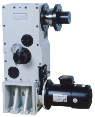
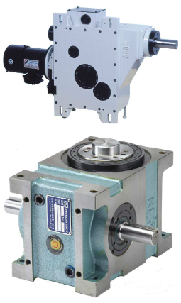
Established in 1980, The Te-shin Cam Co., Ltd. (Te-Shin) is devoted to the design and production of equipment related to computer-aided manufacturing (CAM). Its product line includes critical components, such as automatic tool changers (ATCs) and intervallic cutters.
Te-Shin boasts a large production capacity for this equipment, with a monthly output of up to 3,500 tool changers. It has become a leading industrial supplier of precision machinery in its region, and accounts for 85 percent of the Taiwanese market in its segment. The company’s intervallic cutter features high quality and an excellent cost-performance ratio, and sells for half the price of products imported from Japan.
In recent years, to meet the requirements of high-end, high-precision industries, Te-Shin invested in professional equipment for machining and grinding and adopted an advanced research and development (R&D) process based on 3D design. However, because the previous computer-aided design (CAD) system one of the industry’s leading technologies – used a traditional modeling approach, the company found it difficult to deal with customers’ design changes in real time. This led to a search for a better solution, one that would deliver integrated design, manufacturing and data management functionality to enhance the company’s competitive edge.
After careful assessment, Te-Shin adopted Solid Edge® software from Siemens PLM Software for the drafting and design of all new tool changers. Designers find the new software to be easy to learn and use com-pared with its prior system, which involved complicated instructions and objects inter-related in a hierarchy. Designers found that system dull and time-consuming to use.
In contrast, use of Solid Edge provides an intuitive interface and a component library – a great improvement that allows designers to focus on the design of important system architectures. “What’s more, even our chairman can now easily draft some basic drawings using Solid Edge,” says Cai Peirong, deputy director of the R&D department at Te-Shin.
With Solid Edge, users can import the company’s legacy CAD drawings and manage those files, along with native models created using Solid Edge, thus reducing design and modification time, and decreasing miscommunication between design and manufacturing.
“In the past, in considering whether to adopt 3D design for new product development, our colleagues took the product life-cycle and timeliness into consideration,” explains Peirong. “But the ease of use of Solid Edge, along with the cutting-edge synchronous technology, enables us to use both 2D and 3D data effectively, which furthers the full acceptance and implementation of this new-generation, 3D design system.”
The new system was first used to provide 3D exploded views as required by customers for the purpose of including specifications in maintenance manuals. According to Peirong, “When using the previous 3D software, it normally required three days to draft an exploded view. Using Solid Edge, this is done in one day. Modifying a 3D model is as simple as modifying 2D drawings. We save valuable time.”
In addition, the adoption of synchronous technology means that design data can be updated quickly, which is an important benefit. “The synchronous modeling function allows us to update the change to the assembly drawing as we are changing the part drawing,” says Peirong. “This synchro-nous update capability effectively eliminates the consequence of changing the part drawing only and leaving the assembly drawing unchanged, which consequently might lead to errors in the subsequent operations.”
“In the past, when we used 2D design, there would always be blind angles during product development, which then might lead to collisions,” says Peirong. “In the worst cases, the whole mold would have to be rejected or destroyed. But with Solid Edge, we have effectively addressed the issue of drafting simulation, and avoided interlinked collisions.”
Now, once a design is finished, designers transfer it to a 2D drawing, then deliver it for mold unfolding and machining. At the machining stage, the company uses CAM Express software from Siemens PLM Software, and finds the 5-axis machining capability of CAM Express to be particularly beneficial.
One of the most prominent benefits that the 5-axis machining technology brings is a reduction in errors in tool sequence programming. The company’s original tool changer was manually programmed. Because the machining operation is com-plicated and lengthy, manual operation easily led to errors, and there were different results based on the different skill levels and experience of the operators.
“In the past, the experience of operators easily influenced the accuracy of machining. There were normally hundreds of lines of handwritten programs, and the programming logic, strong or weak, would easily affect the subsequent machining,” says Peirong. “Even if all of those aspects were free of problems, the programming itself was a time-consuming, laborious process.
“With the 5-axis machining capability of CAM Express, automatic tool sequencing and machining execution takes place immediately after drawings are drafted, eliminating a number of problems, including different personnel qualifications, wasted time and so on.”
As Te-Shin’s production capacity increases yearly, there are more requirements for machinery customization. In this context, Solid Edge has become the main tool in Te-Shin’s new product design process, greatly improving the communication efficiency between the company and its customers. For example, there are more than 30 parts in an ATC, and more than one hundred in a power tower. Today, most customers use 3D design drawings to dis-cuss issues related to design changes.
A similar benefit of using 3D is reflected in the convenience it brings in collaborating with overseas customers. Currently, there are users of the company’s tool changers in China, Korea and other areas. With 3D drawings, Te-Shin is able to communicate with those customers clearly regarding design changes, which markedly reduces development time and costs. As Peirong puts it, “The use of 3D drawings helps us eliminate differences resulting from various perspectives, and, to some extent, create a common language for everyone.”
Te-Shin appreciates the rapid and effective technical support provided by Siemens PLM Software’s partner, CADEX, which has been providing assistance since the soft-ware was introduced. CADEX generally deals with any question or issue on the day it arises. CADEX also provides video training that enables designers to become productive quickly. “Most of the time, it is easy to buy a good product, but hard to get good after-sales service,” notes Peirong. “In our deployment of Solid Edge, we have been pleased with both.”
Product: CAM Pro
Industry: Medical Devices and Pharmaceutical
Specializing in R&D and production of implantable medical devices, HC Bio-S is the first company with the ability to develop, design and manufacture dental implants in Taiwan, and has obtained GMP certification, US FDA certification and European CE certification. Since 2013, the company’s focus includes the development of artificial orthopedic implants.
Currently, about half of the company’s products are manufactured directly on turn and mill machines programmed with CAM Express. The other half requires tools in the form of accessories, templates and stamping dies, which are also manufactured with CAM Express. Frank Lin explains: “Running a test in the shortest time possible has always been what we expect from CAM Express. Thanks to the extensive technical experience of Siemens PLM Software and CADEX consultants, we have been able to accomplish our mission in less time. “


