ASM Pacific Technology: Semiconductor and LED equipment supplier uses NX to achieve goal of building smart factories

Product: NX CAM
Industry: Electronics and Semiconductors

Siemens Digital Industries Software solutions enable ASM Pacific Technology Ltd. to improve production efficiency and quality by 70 percent

Looking for solutions to keep pace with advancements in electronics technology

ASM Pacific Technology Ltd. (ASM) is the world’s largest supplier of semiconductor and light-emitting diode (LED) manufacturing and assembly equipment. ASM specializes in providing LED manufacturing and assembly equipment for chip manufacturers, integrated circuit (IC) manufacturing and assembly factories, and consumer electronics manufacturers. With the acceleration of electronics technology advancements, upstream manufacturing equipment providers are tasked with producing more sophisticated equipment in shorter cycle times. As the industry leader, ASM places high value on product development and production, investing 10 percent of its yearly sales revenues into product development. But the system and geographical separations between its research and development centers and manufacturing factories (each with locations throughout Asia and Europe) created significant gaps between ASM’s design, development and production activities.

Overcoming challenges using NX CAM

Directly applying three-dimensional (3D) product models to production/manufacturing activities proved difficult because the models lacked complete product information. Also, it was impossible for the manufacturing processes adopted by the factories to capture design intent, making it difficult for product data to flow between computer-aided design (CAD) and computer-aided manufacturing (CAM).

Because of the significant time required to transfer design changes from the product development center to manufacturing, ASM realized it needed to integrate CAD and CAM. The full integration of design and manufacturing could eliminate problems associated with design and production automation and efficiency, while supporting an upgrade of the company’s business and processes.

“Product development and production are the core parts of ASM,” says Chen Lizhi, director of ASM MIS information and tele-communications technology. “ASM invests 10 percent of sales in product development activities. We have several product development centers and manufacturing factories around the globe. In order to thoroughly eliminate the seamless connection problems in linking design and production, we decided to deploy a computerized system at the production/manufacturing stage, using NX as the standard parts machining soft-ware platform to deploy the computerized system uniformly.

“We began using NX CAM software from Siemens Digital Industries Software in manufacturing factories in 2000. We have deployed more than 100 suites in factories all over the world, including those in Shenzhen, Singapore and Malaysia.” Successful digitalization has pushed productivity to a new level.

FBM keys more efficient processes

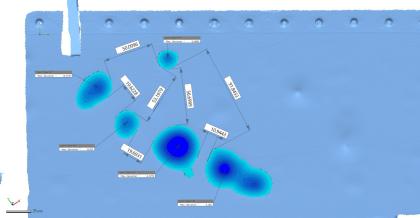
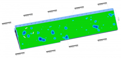
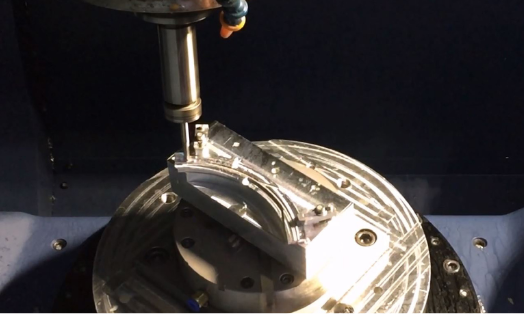
The most immediate benefit of applying NX™ software is that its feature-based machining (FBM) capability eliminates the data barriers between design and manufacturing. With FBM technology, NX CAM can automatically read and identify product and manufacturing information (PMI), tolerances, surface machining precision, and other information attached to 3D product models, and automatically select machining methods, processes and tools while also directly driving numerical control (NC) programming and machining.

In addition, feature-based machining enables automatic transfer of related data between CAD and CAM, and automatically identifies features and creates standardized NC programs for machining processes. ASM can now minimize human error while maximizing efficiency and accuracy.

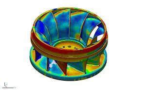
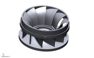
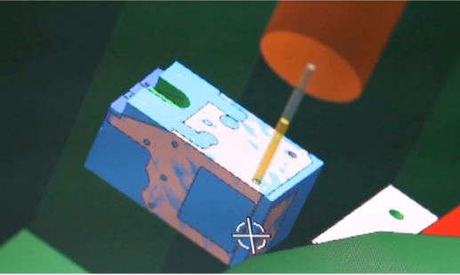
Meanwhile, with the NX CAM integrated simulation and verification (ISV) capability, significantly reducing programming errors and improving machining quality. ASM’s engineers no longer need to conduct tests on physical machine tools. Instead, they can check the NC programming of tool paths for accuracy and reliability in a virtual environment, and verify the tool path and material removal process in a 3D environment. Machine tool simulation driven by G-code drives the true movement of the machine tool’s 3D model (including fixtures and tools), thus ensuring the first-time success of machining in the real world.

With more advanced machining and manufacturing technologies, ASM is marching toward the goal of building smart factories.

“NX CAM’s feature-based machining enables us to truly experience the seamless connection between CAD and CAM, enabling manufacturing to respond more quickly to design changes, thus significantly reducing the time of responding to user requirements and reducing time-to-market,” says Hu Dewen, senior CAD/CAM manufacturing manager at ASM. “Our statistical results show that feature-based machining and PMI have improved the production efficiency and quality of ASM by 70 percent, thus saving a lot of valuable time.”

BOA Dials In to Better Performance Fit Systems with Figure 4 Parts

Product: DLP Printing
Industry: Consumer Products and Retail

Whether they realize it or not, over half of the cyclists in the Tour de France rely on the BOA® Fit System as they churn out mile after mile on the course. BOA is also the common thread that connects workwear, medical bracing, and sports like golf, snowboarding, and trail running – as each integrates BOA’s patented three-part fit system into high-performance products, keeping workers and athletes dialed in.

The BOA Fit System is incorporated into the products of market-leading brands across industries that partner with BOA to give their users the best in performance. Available in a range of power levels designed to match the intensity of the sport and closure force needed for the product, BOA’s performance systems are designed to deliver a fast, effortless, precision fit.

The hunt for functional 3D printed materials

One of the main components of the BOA Fit System is the dial. The dials are engineered to three different power levels depending on the lace tensions achieved by the gear they are fitted to. This includes the high power snowboard dials with gear reductions for high torque that launched BOA’s success in 2001. Daniel Hipwood is a senior design engineer at BOA who spends his time working out the mechanical design for these products.

BOA has been using 3D printing to prototype for several years now, but according to Hipwood, it has been difficult to match BOA’s applications with the material performance they need. Because BOA’s products are small and mechanical properties are paramount, many 3D printing materials could only help BOA with concept verification and aesthetics.

“We’ve been really hamstrung by the materials available to us,” says Hipwood, explaining that the parts BOA was printing were turning brittle and not holding up over time. “We’d have a concept and three days later, if the part fell off a desk in a meeting, it would just shatter into a million pieces. It’s been a real challenge to find thermoplastic-like performance at the resolutions we need, and to actually 3D print parts that function at our scale and can still hold those properties.”

Although BOA’s workflow will still include small runs of pre-production injection molded parts for the foreseeable future, the company wanted to close the gap between 3D printed part durability and final injection molded parts so it could push its designs further, faster, and with greater confidence before beginning the tooling process. Its research led BOA to 3D Systems’ Figure 4 technology and materials.

Figure 4 3D printed part on fingertip

Taking testing farther with Figure 4

Figure 4 is a projection-based additive manufacturing technology that uses a non-contact membrane to combine accuracy and amazing detail fidelity with ultra-fast print speeds. Together with 3D Systems’ production-grade Figure 4 materials, BOA is able to use the Figure 4® Standalone to get early insights into production part performance. Rather than wait the typical three weeks for machined parts, BOA can now assess the viability of its designs in the same afternoon using Figure 4.

BOA uses several of 3D Systems’ Figure 4 materials, and is particularly fond of Figure 4® PRO-BLK 10. Unlike other additive materials BOA has tried in the past, this high precision, production-grade material has long-term environmental stability and thermoplastic-like behavior. This has proved highly beneficial and answered BOA’s search for a material that would deliver resolution and performance with the ability to hold its properties. The material is working exceedingly well for BOA’s purposes, and the company is conducting ongoing correlation tests between final production parts and Figure 4 parts to understand the threshold performance requirements it needs before moving on to production. “Sometimes it’s actually one-to-one, so they’re performing the same as our injection molded components,” says Hipwood.

As part of product development, BOA likes to take viable prototypes and get them on shoes early into the design process so testers can interact with them. Even for designs that will not go on to final production, attaching dials to shoes and putting them through routine abuse helps BOA gather design and performance data on what works and what doesn’t. This aspect of testing requires the dials to be sewn directly into fabric without molded holes. According to Hipwood, finding conventional plastics that can be stitched is difficult enough, let alone finding a UV cured material that will perform without cracking. “Punching a needle through plastic is a toughness problem. You need a material that is resilient, but still maintains enough stiffness to carry out its other uses. Part count reduction is key, so that stitched component may have other important functions that require a stiff plastic material,” says Hipwood. The fact that Figure 4 PRO-BLK 10 can be used to prototype in this manner has been a major help to BOA, saving time and money to quickly iterate its designs for the highest performance.

Along with its fit system, BOA is known for its lifetime warranty: The BOA Guarantee. Product quality out of the gate is paramount and having functional printed parts helps Hipwood and the team of engineers at BOA deliver new innovative products with faster design cycles and less redesign of components after tooling creation. “Everyone is striving to shrink and optimize their products, which makes it critical to identify the weak spots as early in the design process as possible to avoid finding problems when molds have already been created.”

Additional materials in use at BOA include Figure 4® TOUGH-GRY 15, a durable gray prototyping material, and Figure 4® ELAST-BLK 10, an elastomeric prototyping material. Beyond the small mechanical parts inside the lacing dial systems, BOA uses the Figure 4 Standalone to print aesthetic proofs of concept, end-use fixturing, and rubber-grip overmolds.

A track record of success

According to Hipwood, BOA’s decision to invest in 3D Systems’ technology was twofold. The first factor was BOA’s positive experience talking with the 3D Systems team, and the level of support and expertise 3D Systems demonstrated. The second factor was 3D Systems’ track record. As the originator of the 3D printing industry with an established and robust portfolio, BOA was confident in the longevity of its investment if it worked with 3D Systems. “Other options we explored felt kind of like an alpha or beta product that wasn’t quite tested,” says Hipwood. 3D Systems’ clear focus on innovation and advancing the state of additive manufacturing made the company stand out.

BOA is happy with its decision to bring Figure 4 onboard. “There are more than a few people here who can speak to how the printer is helping them validate their work,” says Hipwood.

Interview: Dan Swartz from Ventrac speaks Synchronous and SEU

Product: Solid Edge
Industry: Automotive abd Transportation

“We looked at other products, but the Solid Edge guys were able to show us what we wanted to see, that it was turning a 2d sheet metal part and put it in 3D. They were the only ones to do that, so we went with their product.”

Dan, how did you get involved in Solid Edge First?

I have a bit of a different background from a lot of Solid Edge users. I never went to engineering school or anything like that. I started in the paint line and worked until I entered the engineering office running autoCAD. Eventually I was doing CAD Admin, and it helped make the decision about moving to Solid Edge. We also looked at other products, but the Solid Edge guys were able to show us what we wanted to see, that it was turning a 2d sheet metal part and put it in 3D. They were the only ones to do that, so we went with their product.

We started using Solid Edge with V19 (approx. 2004, two versions before ST1), coming from AutoCAD. Our lead engineer still starts product designs in AutoCAD, but one of the great things about Solid Edge is that bringing autoCAD data is so easy, and we can keep working on design.

I’ve Heard You’ve Been to Solid Edge University A Couple of Times…

Shortly after we started using the software, we also started attending annual conferences. They weren’t called Solid Edge University back then. We attend meetings in Huntsville, Nashville, Cincinnati, Atlanta.

ventrac5.jpg

These conferences are like family reunions. We were Solid Edge SharePoint beta testers, so we can talk to other beta testers and see how they come with the new versions, other Solid Edge users, and we can always see the demos of the new software. Every year there are always new things, never the same, even though we come to these conferences year after year.

There are so many different classes, you really need to take a look at the agenda and choose and choose your interests. There are so many things you can’t do everything. Ventrac usually sends between 2 and 5 people. That way we can separate and each of us sees the sessions we’re interested in. On the way home we compare notes and then back in the office we update the rest of the Solid Edge users on the things that are most important to us.

I know that for a small business like Ventrac, an event like Solid Edge University was very difficult for us to justify the cost. But we went, and what we discovered is access to information and the people we know, it’s a great way to networking, learn some tips and tricks either from other users, or Siemens professionals themselves! If you are struggling in any area on Solid Edge, this is a place to figure out how to do that! You have classes where users like me are sharing what they do and how they use SE. so it’s very easy to relate to someone there. Like Synchronous, if you don’t know how, it’s scary. But go to SEU, attend a synchronous class, and ask questions about those who are using it.

There are some things that confuse me when I’m at one of these conventions. One is when I see companies that don’t keep up with the software. And also when people don’t even try some of the best new features like Synchronous. I’ll talk to someone and they’ll ask me how I do something, and I’ll tell them, and they could say, “I’ve never seen that before” “What version are you in?” “Oh, we’re in like ST2 or something.” Of course you’re going to miss a lot of great new tools when you never upgrade to the latest version.

ventrac2.jpg

Already using ST9?

ST9 has been available for a couple of weeks, and we’re installing it on our Share Point test server. We used to install the new version when we were using only Solid Edge, but since we now use Solid Edge SharePoint, we performed a trial installation to make sure everything works with Share Point.

Shy or Tidy?

We are a sheet metal shop and we work all our straight brakes. Kids in the store like to see drawings coming from Solid Edge. Most of our things are done in Synchronous, although sometimes we come across things that have to be done neatly. It baffles me why more people don’t use Synchronous. It makes a lot more sense. It’s easy to use, and you don’t have to worry about exploiting features or long rebuild times.

Do you have Any Tips for New Solid Edge Users?

The best advice I can give anyone who asks me what to do? Attend the next SEU, stay up-to-date on maintenance versions and packages, and learn synchronously. As I said before, Synchronous has changed CAD Forever. If you’ve never attended a Solid Edge University, start today! It’s worth the money!

ATK: Transforming data into a corporate asset

Product: TEAMCENTER
Industry: Aerospace and Defense

Using the Teamcenter solution for Reporting and Analytics, ATK pulls information from multiple enterprise systems, providing intelligent insight for smarter decisions.

Innovation delivered through PLM

ATK is a premier aerospace and defense company with approximately 17,000 employees working throughout the United States, Puerto Rico and internationally. The company develops and manufactures highly engineered materials and products that support mission-critical applications for its defense, aerospace, and security and sporting customers.

ATK’s business objective is “Innovation Delivered.” To fuel innovation, the company has fully embraced a product lifecycle management (PLM) strategy across its divisions and value chain. Siemens Digital Industries Software solutions – NX™ software, Tecnomatix® software and Teamcenter® software – form the foundation of ATK’s PLM strategy, which spans the product lifecycle. “Our use of PLM extends from portfolio management, to gathering requirements, and then using those requirements throughout all the organizations inside ATK, and even our supply chain outside of ATK, to deliver products that meet our customers’ needs,” explains Jon Jarrett, director of engineering processes and tools at ATK.

The information exists, but how to get at it?

ATK’s PLM database contains a wealth of product and process data, yet it is just one source of information that managers tap as they carry out their programs. Other relevant data resides in financial systems, the company’s enterprise resource planning (ERP) system, the company’s scheduling system, and so on. With critical business information segregated in “silos,” it had become difficult to answer common business questions such as, “What is my first-pass yield?” or “How many documents are needed to support this program and will they all go out on time?”

ATK had been answering such questions by assigning a person to comb through the relevant databases, contact the appropriate people, and prepare a report. Some of thosead hoc reports required as many as 80 hours to generate. And while the company was able to get answers to specific questions this way, managers were not able to use data easily or proactively. In fact, many had created their own spreadsheets and other documents for tracking programs and processes. “People were doing duplicate work and there was no consistent format for those documents,” says Jarrett. “And people were constantly being pinged for information. Those interruptions are very detrimental to productivity. We wanted more efficiency in getting the data out, and we wanted it displayed in a way that everyone could benefit from.”

A BI solution that works with PLM

A business intelligence (BI) solution – software designed to identify, extract and analyze data – seemed to be what ATK needed. The company’s first use of a BI solution for PLM data, however, was a failure. “We went down the path with a certain BI solution to pull PLM data, but it couldn’t understand PLM data models or security rules,” says Paul Nelson, PLM architect at ATK. “We didn’t want people to see data they shouldn’t have access to. We wanted to be able to mine that data for gold, but not make it a free-for-all.”

Next, ATK tried the Teamcenter solution for Reporting and Analytics, which turned out to be a much better solution. Not only is Reporting and Analytics able to work with the Teamcenter data models and security rules, companies can utilize it to extract information from multiple sources, including commercial applications like ATK’s financial systems as well as home-grown programs. In addition, with Reporting and Analytics, users can aggre-gate data from multiple sources into reports and dashboards. Users can explore varying degrees of lower-level data to understand project specifics or higher-level data to get the big picture. ATK’s reports and dashboards typically contain three categories of information – for executives, managers and individual workers.

“Using Reporting and Analytics, we can quickly pull out data that helps us run our business,” says Nelson. “We’re getting gold out of that data now. It’s unlocked, and it can be presented in a way that people understand immediately.” For example, ATK has established a Science and Engineering dashboard that is accessed through a SharePoint portal. “With just a glance, people can see that screen is red or green, and know the status immediately.”

Report writers reassigned; everyone is more efficient

A dashboard showing costs and schedules is displayed continuously on a big-screen TV in a well-traveled place where everyone can see it. In addition to dashboards, ATK has used Reporting and Analytics to develop a number of highly useful reports. This work is done by Tim Gleason, an ATK software engineer, who is now handling a volume of work that required four people previously. “Tim can barely keep up with all the requests for reports, which come from managers and occasionally even from customers,” says Jarrett. “But we used to have four people doing this work. Now it’s just Tim. The others have been reassigned.” Reporting and Analytics’ tools allow Gleason to create reports much faster than anyone could previously, and he appreciates the fact that he can easily arrange the information in any format anyone requests.

A great example of the kind of “gold” that ATK now easily mines from its business systems is one called the “Automated Requirements Volatility Metric (ARVM)” that draws from Teamcenter System Engineering data. “One of the predictive metrics established by the International Council on Systems Engineering (INCOSE) to determine program success is how often requirements change during the life of the program,” explains Nelson. “You’re not going to have a successful program if you’re trying to hit a moving target. The ARVM reports track how many of those baseline requirements are changing on a monthly basis. If they are changing more than a certain threshold, the screen turns red. It’s a way for a program manager to monitor the health of the program.” ATK did track this information in the past. In fact, they had assigned one person to gather data and provide the monthly report. That person has been reassigned.

Other reports used at ATK include one that lets people see all the items they have due within a certain timeframe. “Typically people just get the hammer when they’re behind. This shifts the focus from firefighting to being proactive,” says Nelson. Another report shows managers how many documents must still be completed for a given program. By combining information from the PLM system and the scheduling system, this report can also tell the manager exactly how many hours are needed to complete that work.

In general, the deployment of Reporting and Analytics has made everyone, from executives to engineers, more efficient, according to Jarrett. “People are not being bugged all the time, and they’re not having to do their own Excel reports,” he says. “We are saving thousands of hours this way.” Another advantage of the Teamcenter solution is that information is more current. With reports that formerly took up to 80 hours to create now avail-able automatically, many reports are generated on an hourly, daily or weekly basis rather than monthly. This real-time visibility helps drive data integrity and accuracy. Finally, ATK is seeing its executives take greater advantage of the information in the company’s enterprise systems. “Sure they could do an advanced search of a database, but they are too busy for that,” Nelson explains. “If you break down the barriers, as we have done by giving them a dashboard that’s very graphical and user-friendly, you get more leadership engagement with the data.”

NuVasive Taps AM Ecosystem to Optimize Spine Implant Technology

Product: DMP Print
Industry: Medical

NuVasive saw an opportunity with additive manufacturing (AM) back in 2015. The orthopedic device company recognized that the unique capability of AM to produce complex and optimized shapes could open new avenues in its design and manufacturing of minimally invasive, procedurally integrated spine solutions. The only snag was that no one at the company possessed AM experience.

NuVasive knew that it needed to partner with a service and manufacturing provider for the AM process. The result of that ultimate collaboration was that NuVasive quickly capitalized on the advantages of AM, going from design to market in just over one year with the 2017 launch of Modulus®—now a full implant line.

Picking a partner to grow expertise

Optimized spinal implant by NuVasive produced using 3D printing

Even accounting for the talent and expertise housed within the NuVasive team, hard work combined with strategic innovation allowed the company to successfully design, qualify and bring to market an optimized family of AM implants in 14 months. If this were a subtractively manufactured product, this would be no surprise: NuVasive has a 180,000 square-foot manufacturing facility in West Carrollton, Ohio, where it performs traditional manufacturing day-in and day-out. AM is another story, and the novelty of the approach to the company and its workforce presented unique challenges.

Realizing that they needed outside counsel, NuVasive first identified several topline criteria for selecting its AM expert. The quality and reliability of the available 3D printing technology were both non-negotiable. The company needed software application support to effectively manufacture a novel device. Lastly, it sought a partner that had credibility within the AM industry and could grow alongside NuVasive.

“We were not willing to take any risks in this regard,” said Jeremy Malik, Director of Product Development at NuVasive.

After conducting thorough research, NuVasive chose 3D Systems, with its Direct Metal Printing (DMP) technology and team of application engineers and AM experts, to commercialize Modulus.

Proceeding from concept to commercialization

The design philosophy behind the Modulus line was to utilize new technology in a meaningful way to deliver a final product that is innovative, as opposed to new. According to NuVasive, the company’s goal was to provide the optimal spinal implant without making significant tradeoffs in the process.

3D Systems' metal additive manufacturing machines at the Customer Innovation Center in Denver, CO

The Modulus line balances porosity with load sharing, and each independent SKU is optimized for improved radiolucency. This was achieved through topological optimization, an algorithm-based design strategy that removes excess material that serves no structural or functional purpose. A component that has been topologically optimized is lighter-weight with no adverse impact on strength. In the case of the Modulus line, topological optimization also facilitates better imaging characteristics across all shapes and sizes of implants, giving surgeons a better view into bone fusion during follow-up. In addition, the optimized lattice structure provides a fully porous architecture that creates an environment conducive for bone in-growth.

“We wanted to do things we couldn’t do before,” Malik said. “There is more to this device than simply utilizing a new technology to bring it to market; we used new technology to help drive improved clinical outcomes for patients.” 

Together, the two companies generated a number of file iterations for different ways that the desired devices could be printed, and 3D Systems provided critical industry expertise on print strategies, metallurgy and residual powder removal, among other unfamiliar but impactful AM aspects.

“We didn’t know what we didn’t know,” Malik said. “3D Systems helped educate us on the additive process and worked with us to iron out our process beyond just the printing. We had a lot of open dialogue, and that communication was key to our success.”

Through the process, NuVasive leveraged 3D Systems’ Customer Innovation Centers (CICs). These facilities, and access to the expertise housed within them, provide an ecosystem of AM solutions that include design and manufacturing capabilities, along with premium hardware, software and materials. Covering everything from application development and frontend engineering, to equipment validation, process validation, part qualification and production, 3D Systems’ CICs help companies with various experience levels accelerate innovation through additive technology.

From design to production, NuVasive was able to capitalize on what the technology had to offer in terms of improved functionality without making large initial investments.

The two companies also collaborated beyond design optimization to achieve a qualified AM production workflow. Notwithstanding NuVasive’s track record in earning FDA clearance on products made with traditional manufacturing, using a new process introduced unique regulatory challenges.

According to Malik, NuVasive addressed those issues by leveraging 3D Systems’ data on manufacturing reproducibility in order to bolster its justifications in its FDA submission.

“3D Systems had customers who cleared devices through FDA in the past, so we knew we partnered with someone who had in-house expertise to help us navigate these requirements,” he said. “That was a nice safety net.”

Integrating additive into the portfolio

Fast forward to today, NuVasive is a spine leader in AM with a fully 3D-printed family of FDA-cleared spine implants on the market. The Modulus line is the result of thoughtful design, and balances the benefits of porosity and performance requirements of interbody fusion devices.

In the end, it took NuVasive roughly 14 months to go from concept to commercialization with its Modulus product line. Although this is a fairly standard timeline for traditional manufacturing processes, the company was excited that it was able to maintain the same pacing in its first application of AM.

“It is a significant undertaking to build your production process in addition to designing and building your product,” Malik said. “We were proud we had the ability to develop both, and relied on 3D Systems to help build out our datasets and justifications in order to get us to market.”

As to product manufacturing and deployment, 3D Systems provides supply chain flexibility and fulfills volume production orders internally or through certified partners, as well as helps customers transition to additive production at their own facilities through knowledge and technology transfer.

NuVasive is beginning to do its own titanium 3D printing in-house, and is using DMP technology for R&D prototyping, as well as to better understand how the machines work to continue refining its production process.

“It’s been a huge improvement for us to have that capability on site,” Malik said. “Now we have a legitimate, scalable manufacturing process and the ability for continuous improvement in the future.”

Digitizing metal tools and carbon fiber composite parts with the HandySCAN 3D

Product: HandySCAN 3D
Industry: Machinery and Industrial Equipment

The EADS (European Aeronautics, Defense and Space Company) is an international leader in the aerospace, defense and related services sectors. The company has been using Creaform’s portable 3D measurement products for several years.

More specifically, EADS uses HandySCAN as the MetraSCAN optical CMM scanner to digitize tools and composite parts (carbon/epoxy resin) and to develop comparisons between parts and CAD files. To perform probes, EADS uses the HandyPROBE optical CMM scanner. In addition to VXelements, creaform system data acquisition software, EADS also uses the VXtrack module to perform dynamic measurements, as well as VXlocate, a software module developed through a partnership between Creaform and EADS.

HandySCAN 3D Application Example

As part of a study on the possible geometric distortion of carbon fiber composite parts, and with the help of a HandySCAN 3D device, EADS scanned 1,000 mm x 800 mm tools, as well as 650 x 300 mm parts, in order to evaluate possible deformations after manufacture.

Tool Parts

First, EADS scanned the tools to verify that they met the CAD plan.

Escaneado de herramientas con el HandySCAN 3D

Two of the parts made with this tool were then scanned and the results compared.

Scanning Parts and Results

The second step was to use very powerful simulation tools to calculate the distortion of the parts before they were manufactured, with the aim of comparing the files of the scanned parts.

Simulación

Simulation

The results obtained by EADS allowed to validate the simulation software, developed to optimize the manufacturing range by identifying appropriate parameters and processes.

This project could have been carried out with a peripheral projection scanning system, but the system of these characteristics that EADS possesses cannot be used on such wide surfaces, and the process is much more complex when the two sides of the composite parts are to be measured. In addition, a CCM scanner could have been used, but this option had several drawbacks, as unique measurements had to be made which, in turn, lead to a much longer acquisition time.

“The Creaform system allowed us to quickly scan metal tools and carbon fiber composite parts. Many of the systems available on the market do not work very well with these composite parts, since they are dark in color and sometimes quite bright. The fact that the equipment was portable allowed us to perform measurements at the same manufacturing plant,” explained Catherine Bosquet of EADS’ Healthcare Engineering Department (NDT &shm).

“Before using Creaform systems we used peripheral projection equipment, as we acquired a HOLO3 system more than 15 years ago. We also tested some of the available systems (Konica Minolta, Metris, Steinbichler, Aicon, Kreon Technologies, Ettemeyer, GOM), but Creaform’s 3D measurement solutions convinced us thanks to their rapid acquisition and configuration, ease of use, performance in measuring many types of surface states and portability. He is in charge of the management, strategic direction and development of the entire Creaform Group, as well as its offices around the world.”

Reverse Engineering an Impeller Made Easy with Geomagic Design X

Product: Geomagic Design X
Industry: Industrial Machinery and Heavy Equipment

When small business owner Matthew Percival of 3D Rev Eng was contracted by Dependable Industries, a pattern and tooling shop in Vancouver, British Columbia, to assist in the reverse engineering of a power generation Francis Runner casting, the full power of Geomagic Design X was put to the test.

Percival had a very finite, one-day window of time to 3D scan the part. There was no drawing to confirm against, so he had to be able to work quickly and accurately. The working runner that was being reversed engineered was on its last repair cycle and needed to have a replacement casting ready in one year. The scan data was acquired in about four hours using a hand held scanner.

The deep narrow pockets of the hydraulic passages limited the scanner’s range and made complete data acquisition impossible. With about 85% of the part scanned, Percival knew he had enough to make a complete CAD model using the software from 3D Systems.

CAD model using the software from 3D Systems.

“For me, Design X is the obvious software choice. The ability to generate solid models directly on the scan data is priceless.”

Matthew Percival of 3D Rev Eng

Using the data live on site, Percival was able to create sketches and smooth lofted surfaces between the two sides of the acquired data and conform it to the casting using hands on methods in Geomagic Design X. Doing this revealed a number of interesting details to the customer:

  • The center axis of the impeller was no longer square to the
  • vanes which results in an unbalanced and inefficient part
  • The cast surfaces were badly worn and out of typical tolerance
  • The volume of each cavity was inconsistent
The impeller Scan inside Geomagic Design X

Design X easily overcame these issues. Percival was able to generate sketches on the blade, as well as an accurate smooth surface that he could revolve around the extracted revolution axis. The surface was then trimmed to match the profile and revolved to obtain the proper count of blades. Comparing this data live with color deviation maps to the scan data, Percival was able to ensure that accuracy was within the client’s requirements.

The problem of the part not being on the center axis was easily fixed, since Design X allowed Percival to redesign with design intent. He was able to model the part by extracting the profile, generating a sketch and adjusting the revolution axis to the proper design intent. Lastly, he merged the model and extracted the radii from the scan data, applying it to every blade. Once the model was complete in Design X, he used the software’s LiveTransfer technology to send the entire feature-based solid model into Solidworks and saved it as a native sldprt file for the client.

Using the CAD tools in Design X and the product knowledge provided by the customer, Percival was able to recreate the entire runner as a solid model true to design intent.

Cost savings in decreased downtime of hydro power generation plant

$ 20,000 per day *

Average cost to traditionally reverse engineer a runner

$ 3,800 and 4 days

3D Rev Eng cost

$ 2,500 and 2 days

Cost to manually produce foundry tooling from traditional reverse engineering data

$ 35,000 and 5 weeks

Cost to CNC cut foundry tooling from CAD data made in Geomagic Design X

$22,000 and 3 weeks

Cost savings in finish machining and balancing of a casting made from CNC tooling

$ 3,500

Cost savings and power generation efficiency resulting from highly-accurate hydraulic passages and balancing

UNLIMITED

Conclusion

The successful completion of the Francis Runner project has opened the door for other impeller projects for Percival and 3D Rev Eng. These projects include aquaculture impellers, mining impeller blades and Pelton wheels. Geomagic Design X allows Percival to quickly use complex shapes and surfaces to produce models within hours, which would otherwise have taken weeks.

Node-Audio Evolves Hi-Fi Sound with 3D Printed Speakers

Product: SLS Printer
Industry: Consumer products

Nearly every piece of high-fidelity (hi-fi) equipment seeks to claim live-performance sound quality, yet many of these products are manufactured very similarly to their box speaker counterparts. The HYLIXA loudspeaker by Node-Audio represents a true departure and hi-fi industry breakthrough, made possible by using selective laser sintering (SLS) 3D printing to produce a distinctive, complex cabinet structure. According to David Evans, industrial designer and co-founder of Node, this revolutionary new speaker was not only produced with 3D printing; it was inspired by the capabilities additive manufacturing makes possible.

Seizing the opportunity to create a high-value product

Industrial designers Ashley May and David Evans entered the hi-fi world because they saw an opportunity to do something that had never been done. With access to a 3D Systems SLS 3D printer in their production facility, they put their heads together to devise a high-value, high performance product that took advantage of the additive process.

“It was like a fresh start for us as designers,” says Evans. “We’ve always known how to design things so they could be manufactured in a particular way, whereas this sort of threw everything out the window and opened up our imaginations to what was possible.”

SLS, or selective laser sintering, is an additive manufacturing technology that fuses powdered materials together in a self-supported build style. Because of this layer-by-layer manufacturing process, it is possible to achieve far more complex and organically shaped components than conventional manufacturing methods allow.

Using 3D sound simulations to iterate the ideal design

With the industrial design component under control, Evans and May enlisted the help of an acoustic engineer to guide the technical development of a new loudspeaker. Their vision was to create a loudspeaker that produces audio quality that rivals a live experience, with beautiful, sculptural aesthetics.

The development process began with 3D designs from Evans and May that then ran through specialized 3D audio simulation software to inform the next iteration. As the simulation output began to confirm the next-level sound the team was after, they began to prototype and refine further, until finally arriving at Node’s flagship product, HYLIXA.

HYLIXA speakers feature a conical cabinet with a patent-pending helical transmission line that spirals for 1.6 meters around the cabinet interior. This line is fed by a dedicated bass driver and releases the sound through a circular vent around the mid and the tweeter. Because the rounded cabinet is designed and manufactured as a single piece, there are no edges to produce diffraction (a disruption to sound precision). This results in smooth sound travel and an enhanced listening experience. According to a review on the hi-fi music gear website The Ear, “the [more complex] the music gets, the better [HYLIXA] sounds, which is the opposite of what you get with most speakers.”

HYLIXA loud speakers by Node Audio

Maximizing technology in design and production

Production and prototyping for the HYLIXA speakers are done on a 3D Systems sPro™ 60 SLS printer. The speakers, which are sold in a set of two, are each printed separately within the printer’s 381 mm x 330 mm x 460 mm build volume. Evans says the team maximizes each build by nesting the other components within the speaker cabinet.

The cabinet and front baffle components of HYLIXA are printed in DuraForm® GF, a glass-filled engineering plastic that delivers an excellent surface finish that is machinable and paintable. As the primary display piece of the speakers, Node puts the HYLIXA cabinets through a methodical post-processing regimen to evacuate all material from the pieces and prepare the surfaces for whatever finishing the customer requests. 

“We learned through the prototyping process that DuraForm GF actually worked very well acoustically,” says Evans. “It has almost a ceramic-like quality to the touch, which helped us both structurally and sonically. As designers, we could freely exploit SLS production to create the internal structure, but also design something that looked as beautiful as it sounds.”

“Every component that we 3D printed, we’ve done for a reason,” says Evans. “We’ve used the technology to benefit the product in one way or another, and pushed to take everything to the absolute limit.”

Close up of SLS produced loud speaker HYLIXA

Reception in the industry and future products

After launching HYLIXA in 2019, Node sent several pairs of speakers to hi-fi industry experts for their unbiased take. In addition to descriptions such as “radical,” “unusual,” and “seductive,” publication Hi-Fi+ praises the speakers for “an almost unbelievable ‘out of the box’ sound” with “an exceptional dynamic range.” 

“The feedback has been even better than we first hoped, to be honest,” said Evans. Having now earned credibility within the industry, Node has more up its sleeves and is looking to grow. Evans says what’s to come is still “very top secret” at the moment, but Node remains committed to its process. 3D printing will be an integral part of the company’s strategy to differentiate itself by doing things that haven’t been done before.

Learn more about this story here.

An encounter between prehistory and high technology, where Artec Leo comes face to face with a dinosaur skull

Product: Artec Leo
Industry: Academic

Dinosaurs – Creatures that have inspired study and research for centuries, and continue to intrigue millions of people around the world today. For the preserved remains of a triceratops roaming the Earth in prehistoric times, modern technology has attributed a status few dinosaur fossils have achieved: digital immortality.

Originally discovered in 1891 near the village of Lance Creek, Wyoming, the skull of this herbivore was exhibited at the Smithsonian Institution in Washington, D.C. until the late 1970s. He was then loaned to the CU Museum, where he now resides; the current museum was literally built around this skull.

“The Smithsonian estimated how much it would cost to tear down that wall, pull this thing out and return it, because they own it, and it was so expensive and risky that no one wanted to do it,” says Nick Conklin, Application Engineer II of Artec’s certified partner Gold, 3D Printing Colorado. This means that the skull, in principle, stays where it is, but with 3D scanning technology, there are now previously impossible possibilities.

When Conklin and his partner David Cano first visited the University of Colorado Museum of Natural History in January this year, it was for sale by a Artec Leo 3D scanner. “As we entered, we saw the skull of the triceratops and thought, ‘Hey, that would be a really cool scan, we should do it sometime!'” conklin recalls.

With each scanner that sells 3D Printing Colorado, training is included. But for Dr. William Taylor, curator of archaeology at the university, already familiar with Artec 3D scanners, another add-on was suggested.

“Dr. Taylor had already used artec Space Spider a lot, so instead of training, he decided to bring the Leo to one of his classes,” Conklin says. “He wanted us to show his students what can be done with Leo and scanning technology.”

Thus began a project of prehistoric proportions, to digitize a dinosaur skull completely.

“For 30 or 40 minutes, at one of Dr. Taylor’s night classes, I was scanning the skull of the triceratops while talking to the students, explaining what he was doing, so it was a great apprenticeship,” Conklin says. This skull scan quickly caught CU Media’s attention.

“The university’s media was everywhere, and they wanted to take pictures and videos of a dinosaur being scanned,” says Cano. “Once they found out about this, they invited us back, and this time instead of a teaching experience, it was more of a movie photo shoot,” Conklin adds.

During his second scan, something helped a lot in the session, a ladder. “With the ladder, I was able to get some details that had slipped away from me before, so it was much better,” Conklin says.

The scan took a total of 30 minutes, while the scan processing was completed in artec Studio3D software in two hours.

Using Leo, most of the surfaces were near the ground. “I was able to get everything except the top peaks from the ground with my normal range and range of motion,” Conklin says. “With his large field of view and the ease with which Leo gets the data, it was very easy. I wasn’t just scanning, as I was talking and explaining what I was doing.”

As easy to use as recording a video with your mobile, Artec Leo comes with a screen, which means you can see if you’ve captured all the areas and fill in the ones that could have been left. 3D replication is generated in real time as you scan, so you can focus on the work, how in this case, scan while demonstrating PhD students on a ladder.

“With another scanner I could have done it, but it would have been harder, I would have had to pay more attention to everything. But with Leo and how well he tracks, I was able to divide my attention between class and quality data collection. It’s definitely the best tool for this job.”

Conklin says that being able to access the skull with a ladder made the data obtained much better, as he was able to scan both the back and top of the skull and from all angles. “I liked the end result a lot more,” he says. “My biggest concern was that it’s an irreplaceable piece of archaeology, and if anything had happened to him. I don’t even want to think about it.”

Thanks to this scan, in addition to having a 3D model of the museum star, many other companies and faculties can find educational and professional opportunities. In essence, what inspires the team is the ability to do something that was previously impossible.

“Especially now that everyone stays at home, you can work from home and do whatever you want from a 3D file, such as performing simulations or conducting research,” Conklin says.

“Supporting research that would not otherwise be possible is another reason why this is important, in addition to the fact that anyone, anywhere in the world can start researching from this copy.”

From measurements to research, from global accessibility to preservation, opportunities are limitless. “Even maybe for the CGI for the next Jurassic Park movie, or video games,” Conklin suggests. “I’m excited to think about it!”

“Just to see how history is done and preserved, to see how the world changes, how something that would have been destroyed over time or for any other reason can be preserved, time passes for all, but if we can digitize things, we can go back in time eternally.”

Today, what the home of the skull has been considering is using scanning to make a mold and then create its own copy on the Smithsonian, now that they have the exact measurements of the entire skull, something they had never had before. “I don’t think we could have done it without the 3D scan,” says Conklin, who is happy to fulfill his childhood dream of wearing the archaeologist’s hat for a day. “I’ll tell you what,” he adds. “If you build a replica of this dinosaur skull from my scanning data, I’ll bring my future grandchildren to see!”

“I would like to go a step further and see what we can do with the museum in terms of digitization and help them in the long run,” Cano stresses.

easyJet Cuts Aircraft Damage Assessment Time by 80% with Geomagic Control X

Product: Control X
Industry: Aerospace

If you’ve flown anywhere in Europe in the past two decades, chances are good that you’ve flown on easyJet. This leading European low-cost airline brings travelers to more than 30 countries on 600+ routes safely and conveniently, all while offering some of the lowest fares across the continent. How do they do it? With a focus on safety, simplicity, and operational efficiency. easyJet’s engineering organization epitomizes this ethos by putting safety at the heart of everything it does and innovating to continually improve performance and reduce costs.

easyJet assesses aircraft damage faster with Geomagic Control X

Minimizing Aircraft on Ground Time

One of the most important ways that easyJet can minimize delays and keep ticket prices low is reducing Aircraft on Ground (AOG) time. Unplanned AOG events happen when any of the company’s 298 Airbus aircraft are damaged or experience mechanical failures, and can be very costly — not to mention inconvenient to passengers. It’s clear that the faster a damaged aircraft can be checked, the better it is for the airline and its passengers. 

“One of our biggest challenges is to try and reduce the AOG time of aircraft and maintain accurate records when damage occurs,” said Andrew Knight, Fleet Structures Engineer at easyJet. While rare, hail, bird strikes, and other events can potentially damage the wings and fuselage and require inspection before flying again. Checking damage from these types of events has traditionally been a low tech, manual, and time-consuming process that requires maintenance staff to assess aircraft damage using manual measuring tools such as rulers and vernier calipers. Worse still, interpreting the extent of any damage using this technique is highly subjective and not repeatable between staff members. easyJet’s structural engineering team went looking for a modern solution to speed things up and provide more accurate, traceable results.

3D scanned deviation location using Geomagic Control X

Repeatable, Accurate, Mobile 3D Inspection

“We’ve been looking for a system that is easy to use for the maintenance engineer but has the ability to provide more in-depth reports if required by support staff. It must be accurate, repeatable and most of all, mobile, as AOG events can occur anywhere within our network of 136 destinations across Europe,” Knight continued. “The biggest challenge was the software side because it needed to be a simple, easy-to-use interface to obtain a basic damage report, but powerful enough to provide more in-depth details in the support offices. 3D scanning should provide us with accurate, fast damage assessment with repeatable results independent of the experience of the user.”

For these reasons, easyJet turned to 3D Systems reseller OR3D, a UK firm with expertise in 3D scanning and Geomagic software. Robert Wells, a 3D scanning expert at OR3D, reported that “based on easyJet’s requirement to quickly scan large areas — such as the entire wing length of an Airbus A320 — on the tarmac, we recommended a portable handheld 3D scanner. And we knew Geomagic Control X™ was the right software because they needed an automated way to assess dents that was easy for their staff to learn and use.” With this solution, performing a damage assessment on the roughly 70 feet (21 meters) of an A320’s flaps takes just a few hours, compared to several days with wax rubbings on tracing paper, saving easyJet tens of thousands of Pounds/Euros per damage event.

Geomagic Control X inspection shows dent locations to easyJet quickly and accurately

Instant Reporting for Fast Documentation

Once the scans are complete, easyJet engineers can get damage reports from Geomagic Control X software on the spot. They don’t need to load CAD models or align the scan data to anything else in the software, and they don’t need to have deep metrology expertise to get reliable output. Control X uses its CAD engine to automatically create idealized geometry that meets standards for surface continuity that are defined by Airbus, and measures the scanned aircraft against that idealized geometry to provide instant results. Within minutes, easyJet engineers have a consistent, repeatable, and thoroughly documented initial damage report that lets them decide what repairs, if any, are needed before the aircraft can be placed back into service.

Powerful 3D Inspection That’s Easy to Learn

easyJet has embraced Control X for large-scale damage assessments because it’s so accessible for busy engineers with many other responsibilities. Knight remarked on this specifically, saying “engineers will not use the system if it is too complex and requires in-depth software knowledge and/or extensive training.” Control X fulfills these requirements better than any other scan-based inspection software because it’s intuitive, easy to learn, and powerful enough to handle complex measurement scenarios. Anyone familiar with using 3D software can pick up Control X and get results in a matter of minutes, with the flexibility to measure what they need to, without pre-programming or inflexible macros.

What does this new, modern approach to damage inspection mean for easyJet? “We have estimated an approximate 80% savings in time to perform assessments using the 3D systems we currently have with a potential 80% savings in currency terms,” says Knight. There are additional benefits beyond reduced AOG time and better decision-making regarding repairs as well: keeping detailed damage reports, complete with accurate scan data, can help the company years from now when it comes time to sell or return aircraft to their leaseholders.

easyJet’s use of Control X is another example of how simple, intuitive inspection software helps companies ensure quality everywhere by empowering more people to measure more things in more places. Learn more about Geomagic Control X today.

×