Construction: measurement of test specimens and evaluation of imperfections

Product: HandySCAN
Industry: Academic

The Chair of Metal Structures at the Technical University of Munich has been contributing to the development of steel and light metal structures within the construction industry for many decades. There is a long-standing tradition in the areas of bridge design, stability, construction, composite structures, fatigue and glass works. However, other current matters are also continuously addressed, and new priorities are set. In recent years, research efforts in fire and explosion safety have intensified, thus requiring highly complex numerical investigations in addition to experimental validation.

Measuring System Requirements and Challenges

Given their experimental approach supplemented by numerical experiments, the Chair expressed great interest in the exact dimensions of the test specimens—in this case, columns. They would later be used as reference for inspections. The measurement tasks for test specimens were often outsourced. For one thing, this was very costly and therefore restricted 3D measurements to isolated test specimens.

The following criteria played a decisive role in the search for a 3D measuring technology: Precision, workability of the measured data in widely used civil engineering software, easy-to-use functionality, as well as short scanning and inspection time. Based on various factors, the decision was finally made in favor of the HandySCAN BLACK from Creaform. This portable 3D scanner distinguishes itself from other devices on the market by its wide range of measurement possibilities, the compatibility of the data with common CAD software, its already proven and widespread use in well-known companies, and a compelling product design.

Scan of Heavy-Duty Composite Column Geometries

In order to identify misalignments and curvatures of high-strength composite columns, geometric imperfections had to be scanned. Unfortunately, columns are not always perfectly straight. Deviations from the ideal shape often occur during production. These deviations are known as imperfections, and they have a variable influence on the bearing load of the component, depending on how far from the ideal shape the deviations are. For components subject to compressive stress, these imperfections lead to a reduction in the bearing load capacity, which depends on the degree of deviation. By measuring them with a 3D scanner, we can obtain important information about the dimensioning of the components.

Composite column is scanned with HandySCAN BLACK

Columns of up to 4 meters long can be scanned relatively easily with the HandySCAN 3D. Positioning targets are placed on the pipe and the pipe is placed in an upright position. This allows the contour to be measured quickly and easily from all sides—including the curved cylinder surface and the cross-sectional contour at the end of the pipe.

The 3D measurements provide information about the imperfections of the component. However, the component had to be modeled separately in an finite element (FE) environment and given equivalent imperfections that represent not only the geometric, but also the structural imperfections. The calibration of these equivalent imperfections is based on the scan and test results. After a period of adjustment, the scans were assessed in VXinspect. Dimensional inspection software such as VXinspect facilitates analysis by means of built-in functions; in the case of pipes, for example, cylindricity is important.

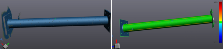
Scan and CAD of a high-strength composite column with color deviation

The impact of the internal stresses and imperfections incorporated in the finite element models can now be quantified with measurements before they actually appear. This avoids resorting to benchmark values, and calibrating these variables afterwards according to the experiments conducted.

“Creaform greatly facilitates and enriches our research in the field of steel construction, and will prove indispensable in any experimental project in the future. Since we also have our own 3D scanner, we can now measure a large number of test specimens ourselves. This results in greater flexibility, and considerable cost savings, since we no longer need contractors,” says Prof. Martin Mensinger, Head of the Chair of Metal Structures at the Technical University of Munich.

Oakland University uses Siemens Digital Industries Software tools to provide experiential learning and connect students with companies

Product: Teamcenter
Industry: Academic

Since we integrated Plant Simulation into our program, a wide variety of companies have contacted me requesting help to fill fulltime throughput simulation positions. And with the launch of the Plant Simulation internship program, we expect that number to grow.

Robert Van Til, Pawley Professor Chair
ISE Department Oakland University

Preparing engineering students for Industry 4.0

Located in Rochester, Michigan, Oakland University is a public university whose School of Engineering and Computer Science is a major driver in the institution’s growing reputation. The school’s Industrial and Systems Engineering (ISE) department was founded in 2005 and features undergraduate, masters and doctorate level programs in industrial and systems engineering, engineering management, and systems engineering.  

The ISE department became a Siemens Digital Industries Software academic partner in 2011. Since then, the department has integrated several tools from Siemens Digital Industries Software’s Tecnomatix® portfolio, including Plant Simulation, Jack™ software and Process Simulate Robotics as well as solutions from the Teamcenter® software portfolio, into undergraduate and graduate engineering courses. And the ISE department is currently integrating Insights Hub, the industrial IoT solution from Siemens, along with Opcenter® suite into some courses which are all part of the Siemens Xcelerator business platform of software, hardware and services.

Several ISE department graduates have secured full-time positions with well over a dozen companies working on various aspects of Industry 4.0, with approximately 10 of those companies hiring Oakland University students for their knowledge of Plant Simulation. Due to the use of Plant Simulation and other Siemens Digital Industries Software tools, the academic partnership program has helped Oakland University develop relationships with many companies who were previously unaware of the ISE department’s programs.Preparing engineering students for Industry 4.0Preparing engineering students for Industry 4.0Preparing engineering students for Industry 4.0Preparing engineering students for Industry 4.0

Creating a hands-on throughput simulation course

After using Plant Simulation in some existing courses, the ISE department found that many students, as well as the companies hiring its graduates, suggested the development of a new course that takes a deeper-dive into the use of the tool and its application. This led to the creation of a new half-semester course titled PLM Applications – Throughput Simulation. The course combines education with some training, teaching students to operate Plant Simulation and use the tool to complete various hands-on throughput simulation assignments.

With discrete event simulation of manufacturing and other systems becoming increasingly vital to industry, the course focuses on using Plant Simulation to build, run and analyze discrete event simulations of systems and to present the results. Students learn about the creation and usage of a digital twin to reduce risk and return value. The course covers requirements analysis, model creation, validation, and a “what if” analysis. 

To better serve working engineers the course is offered in the evenings. Robert Van Til, Pawley professor and chair of the ISE department says, “A large percentage of students in our masters’ programs are full-time working engineers since all graduate courses are offered in the evenings. We also get working engineers taking this course as well as other PLM-related courses as non-degree students.”Creating a hands-on throughput simulation courseCreating a hands-on throughput simulation courseCreating a hands-on throughput simulation course

Experiential learning through the Plant Simulation internship program

Experiential learning allows students to take the concepts and techniques learned in the classroom and apply them to realworld problems in an industrial environment. Through the Plant Simulation internship program, Oakland University’s ISE students participate in experiential learning. The paid internship program consists of four parts: 

  • The ISE department works with companies to recruit and interview ISE students to serve as a Plant Simulation intern, with the company making the final selection  
  • The intern is paid to take the PLM Applications – Throughput Simulation course to learn Plant Simulation during the fall semester. The company also selects a throughput simulation project for the intern, in consultation with ISE faculty members, during the fall semester
  • The intern is paid to work part-time on the throughput simulation project under company supervision with the assistance of an ISE faculty member during the winter semester, approximately 12 to 15 hours per week. The intern works on the project either in Oakland University’s Product Lifecycle Management (PLM) laboratory or at the company’s facility while taking classes. If the intern works primarily at Oakland University, he or she will still spend time at the company’s facility to learn about the system being modeled, collect data, etc.
  •  The intern is paid to work on the project full-time during the summer, again either in Oakland University’s PLM Laboratory, at the company’s facility or at a mixture of the two locations

The internship program was piloted during the 2018-19 school year. Plant Simulation interns were placed at an aerospace company and an automotive original equipment manufacturer (OEM).

Oakland ISE undergraduate student Brianna Walters’ internship project at an aerospace company focuses on using Automated Guided Vehicles (AGV) and Mounted Robot Guided Vehicles (MRGV) to move parts and tools through a job shop type model. Walters notes, “The company initially had me using my Plant Simulation model to explore the software and its capabilities. Next, we plan to look at machine and transporter utilization.” 

While Walters was originally scheduled to serve her internship during the summer of 2019, the company was so impressed by her work that they have hired her to a full-time engineering position.

Another ISE undergraduate student, Mick Packard, is interning at an automotive OEM. His project involves several steps:

1. Shadow company and Siemens team members during initial weeks, observing the business actions and practices of the group while continuing to build on knowledge of Plant Simulation and model design techniques.

2. Create a digital twin model of an engine block machining line, then validate the model to a level of statistical significance while meeting key performance standards.

3. Run pallet optimization tests and buffer sensitivity analysis using the model.

4. Design “what if” scenarios based on optimizing line performance.

5. Create a report on the project; breaking down the process of building the model, features included in the model for re-usability and continued tests, accuracy of model, results of “what if” scenarios, as well as challenges and struggles.

6. Finally, present results to company managers, team members and plant engineers. Also, provide an in-depth knowledge transfer opportunity for other company engineers on model practices/features.

“This internship has been an amazing experience,” says Packard. “It’s great to take the tools and techniques we are learning in our Oakland classes and apply them to real-world engineering problems.”

The Plant Simulation internship program is being offered to other large companies as well as to small-to-medium sized businesses (SMB). Many SMB are evaluating the value of integrating PLM tools such as Plant Simulation into their operations. The internship program offers a cost-effective way to conduct an independent throughput simulation evaluation study on a company’s existing system without purchasing a license or training existing personnel. 

After the project is completed, the Plant Simulation internship program also provides companies with the option of hiring the intern, who is not only educated in discrete event simulation and trained in the use of Plant Simulation but is also familiar with the company.

The early results of the program have exceeded Oakland University’s expectations as demand for graduates with throughput simulation experience with Plant Simulation has far exceeded the supply.

“Since we integrated Plant Simulation into our program, a wide variety of companies have contacted me requesting help to fill full-time throughput simulation positions,” says Van Til. “And with the launch of the Plant Simulation internship program, we expect that number to grow.”Experiential learning through the Plant Simulation internship program Experiential learning through the Plant Simulation internship program Experiential learning through the Plant Simulation internship program Experiential learning through the Plant Simulation internship program Experiential learning through the Plant Simulation internship program

Plans for the future

Oakland University is considering expanding the Plant Simulation internship program into an Industry 4.0 internship program with the addition of internship opportunities that focus on ergonomics and robotics by using the Jack and Process Simulate Robotics tools, respectively. This should be relatively straightforward since the ISE department already offers handson courses on both Jack and Process Simulate Robotics.

The company initially had me using my Plant Simulation model to explore the software and its capabilities. Next, we plan to look at machine and transporter utilization.

Brianna Walters, Student, Intern at aerospace company
Oakland University

How a mountain bike enthusiast designed and manufactured his custom carbon fiber bike from scratch with Siemens NX

Product: NX CAD
Industry: Academic

Siemens is not only offering products to big companies, but also small and medium businesses and even private persons can subscribe and benefit from the Siemens Xcelerator portfolio of software and services. This is what this case demonstrates:

We recently found out about the project completed by a German mountain bike enthusiast, who calls himself Uncle Bob, and his journey that started with an empty screen and ended with custom self-built carbon fiber mountain bike.

Uncle Bob’s journey

Due to an injury from biking, Uncle Bob needed a new project to keep himself entertained. He is the founder of an engineering consultancy, which is why he owned the Siemens NX CAD software and has experience with it. So, in his free time he just started directly scribbling in Siemens NX with a try and error approach and with the following weeks, his ideas became a solid concept. 

mountain bike in forest

Bob was especially delighted with the plentiful and individual 3D visualization options NX had to offer, they enabled him to work creatively and to see the realistic result of his design before building. 

Considering the design, Uncle Bob has gone for a form follows function approach: “If something already looks like something that will not last, it surely will not last during tests.” 

Why NX?

Apart from the design aspect, he really appreciates NX for the ability to test and verify his CAD design data into finite element analysis (FEA) simulation tools, which he uses in his daily professional life as well as with this bike. “I have not regretted the investment for Siemens NX, it was worth it and definitely helped me to ease up processes. Before NX, I had to copy data manually from program to program. The implementation of NX at Daimler got me starting to look out for better solutions.” 

bike model inside of nx

So, an FEA study was done to stress test the frame and structure. After all, mountain bikes like these need to withstand high physical forces due to big jumps, loose ground and high speeds. And his bike did!

For example, his calculations resulted that the frame around the bottom bracket can withstand jumps or falls with more than 6,000N. For the areas that failed his tests, the layup of the composite material was modified in Siemens NX and additional plies were added to strengthen these areas.

Getting started and getting building with NX

bike model mold

With a flaw free concept ready, he designed an injection mold in Siemens NX that he could use for producing the carbon-fiber parts. Due to the extensive 3D features in Siemens NX, he could make the mold as material efficient and small as possible.  Then he started working in his garage: A wax core was casted that represents the inner geometry of the carbon frame. Then, he wrapped the carbon fiber around it and closed the mold airtight. Using vacuum and high pressure a hardening resign was injected into the mold. After a few hours of tempering the resign was hardened and with higher temperature the wax core melted and flowed out. Now the frame was made. He didn’t clearcoat the frame because Uncle Joe was confident enough that his construction and his materials used were sufficiently durable anyway.

After that, the frame was made and he started to assemble all the custom frame parts and bought standard parts together. A few weeks later it was all done, a extreme mountain fat bike, that all-in-all only weighted 17kg, with the NX constructed custom carbon forged frame only taking 3kg part of that. After his first test ride, Bob was beyond impressed:

“Insane! Sore muscles in the face because of the permanent grin. I can only say: Dreamy. The bike fits me like a glove.”

Winery Tops Off Tour with 3D Printed Map of Vineyard

Product: CJP
Industry: Academic

Wine aficionados already know: the environment in which wine grapes grow impacts the final characteristics of the wine. Some subtly, some not so subtly. This element is known as terroir, a term that describes the complete natural environment from which a wine comes, including the climate and topography all the way down to the soil. These variables are anything but inconsequential to the flavor, color and body of the wine, and can be fascinating to learn about. Yet short of walking through a vineyard with surveying poles and kneeling to rub earth between your fingers, it can be challenging to get a comprehensive picture of terroir to fully appreciate the nuances at play in your glass.

This was a problem for Ten Minutes by Tractor, a winery on the Mornington Peninsula, Australia, that wanted to give its patrons a deeper understanding of its wines. Ten Minutes by Tractor is made up of three vineyards located ten minutes apart with widely different environmental characteristics that deliver vastly distinctive wines. The winery’s goal is to add value to its wine tour experience wherever possible by sharing its knowledge of wine making with its visitors. Yet verbally explaining the impact and differences in terroir proved minimally engaging without a visual reference. The winery needed a way to clearly communicate the contributions of the region to its wines that was accessible and effective.

vW Maps, a trusted publisher of Australian wine regions, offered a solution and worked with the vineyard to create a digital 3D appearance model of the terrain. Using a scaled representation, the winery could show visitors the spatial relationship of the vineyards to one another as well as the interplay of environmental features that were responsible for creating distinctive character among the wines. vW Maps further transformed the 3D data into a 3D printed appearance model at 1:160,000 scale with a five-fold elevation exaggeration. The final 3D printed models could then be examined and discussed as a memorable

vW Maps merged graphic and cartographic design to create the data for the 3D printed map.

Designing a 3D map of vineyard terrain

vW Maps took great care to merge and adapt graphic and cartographic design elements to get an effective mix of terrain selection, generalization and simplification with the right typography, color and balance. The resulting representation focuses viewer attention on the vineyards, terrain and most important landmarks. This allows cellar door staff at Ten Minutes by Tractor to easily reference and explain the complicated factors of terroir over a scaled appearance model of the terrain that is distinctive, appealing and easy to read. The map also helps cement the cellar door experience in visitors’ minds as a unique learning aid and conversation piece that stands out from other wineries in the region.

According to vW Maps Owner Martin von Wyss, although the appearance model design was digital in origin, “The terrain model is tangible and accessible when placed on the tasting bench next to a glass of wine, and it makes the geography of wine fun, engaging and easy to understand.”

Through an examination of the “Terroir Explainer,” as von Wyss calls the model, winery customers gain an understanding of the vineyards’ physical conditions, such as elevation, slope, aspect, and drainage. The cellar door staff supplements the 3D printed model with additional information about soil and climatic conditions to complete the picture of what shapes the wine. Von Wyss says the 3D printed appearance model effectively highlights the many variables at play in viticulture to sharpen environmental awareness, heighten respect for the vineyards and deepen clients’ appreciation of the nuances of wine.

The 3D printed model was created at 1:160,000 scale with a five-fold elevation exaggeration.

3D printing terrain maps in full color

Once vW Maps had prepared the 3D terrain data, it sent separate files for the topography and map to 3D Systems On Demand Manufacturing services. Once received, 3D Systems’ manufacturing experts scaled and wrapped the design data onto the 3D file for printing in full color using a ProJet® CJP 660Pro. This printer uses 3D Systems’ ColorJet Printing (CJP) technology, a powder printing process popular for detailed, multicolor parts in architecture, consumer goods, the arts and other applications where color and appearance are of primary value. Offering photorealistic color in a full CMYK spectrum, the build envelop of the ProJet 660Pro is capable of producing large prints in a single piece. vW Maps and Ten Minutes by Tractor took advantage of this large print size, with final model dimensions of 252mm x 379mm x 18mm.

3D Systems’ On Demand Manufacturing experts prepared, printed and finished the model within the week and promptly sent it back to vW Maps for final delivery. Next to the wine, the 3D printed appearance model is the centerpiece of the cellar door experience at Ten Minutes by Tractor. According to the winery’s general manager Chris Hamilton, it also helps Ten Minutes by Tractor stand out and garner word-of-mouth interest. “There’s no doubt that our terrain map is a key component that makes a visit to our cellar door distinctive from visits to our nearby competitors,” says Hamilton.

The terrain appearance model was a finalist in the 2016 Victorian Design Awards, which recognizes and awards Victorian designers and businesses that demonstrate excellence in their use of design.

The terrain appearance model was a finalist in the 2016 Victorian Design Awards

Monash University Revolutionizes Human Anatomy Study

Product: CJP Print
Industry: Academic

Thanks to McMenamin and 3D printing, the cadaver, in all its full-scale and full-color glory, is gaining a new lease on life in medical universities around the world.

For hundreds of years, the human cadaver has been a critical tool for medical teaching, but it’s been problematic for reasons as diverse as cost, transport, storage, spiritual beliefs or just general queasiness.

Monash University in Australia might finally have the answer to a majority of these obstacles: The first commercially available kit of realistic, full-color body parts produced by a 3D printer. 

A paper from Monash University titled “The Production of Anatomical Teaching Resources Using Three-Dimensional Printing Technology” lists several advantages of using 3D printed cadavers, including “accuracy, ease of reproduction, cost-effectiveness and the avoidance of health and safety issues associated with wet fixed cadaver specimens or plastinated specimens.”

Looking inside the body

3D printed, full color hand for use by medical students

Specimens are printed by Monash using 3D Systems ColorJet Printing (CJP) technology. The ProJet series of color printers are easy to use. Most importantly, they produce models in the exact colors that Monash needs for realistic 3D printed body parts.

“The full color is essential to reproducing a combination of realistic color fidelity and ‘coding’—vessels in red or blue, nerves in yellow, for example—that is valuable in teaching,” says Paul McMenamin, director of the Centre for Human Anatomy Education (CHAE) at Monash University.

McMenamin believes his team’s simple and cost-effective anatomical kit could dramatically improve knowledge for medical students and practicing doctors. It could even contribute to better surgical outcomes for patients.

“For centuries cadavers bequested to medical schools have been used to teach students about human anatomy, a practice that continues today,” says McMenamin. “However, many medical schools report either a shortage of cadavers or find their handling and  storage too expensive as a result of strict regulations governing where cadavers can be dissected.

“We believe our kit will revolutionize learning for medical students by enabling them to look inside the body and see the muscles, tendons, ligaments and blood vessels. At the moment it can be incredibly hard for students to understand the three-dimensional form of human anatomy, and we believe this kit will make a  huge difference.”

Realizing an ‘ah ha’ moment
Marcando la diferencia en Liberia

3D printed, full-color model of the brain highlights venous arterial circulation

Cadavers printed in 3D might seem like a logical progression for the medical community, but it took technological progress in 3D printing to make it happen. The 3D Systems machines used by Monash University deliver the ability to print full-color models at relatively high speeds at a cost that provides a marked improvement over plastic models or plastination of human remains.

“I was looking for a way to produce more anatomy prosections and maybe plastinate them, but realized it would take decades and more than a half-million dollars to set up a plastination lab,” says McMenamin. “Each specimen would have to be dissected and prepared and then I would have one of that specimen.

“So we thought ‘why don’t we scan them (CT or laser), make color STL or VRML files, and print them so we can make lots of copies’. Seems obvious now, but it was sort of an ‘ah ha’ moment.”

Thanks to the 3D Systems printers, Monash University can produce parts that range from a full body to head and neck, upper limb, pelvis and lower limb, and thoracic and abdominal regions. A deal with German anatomical model makers Erler-Zimmer makes the cadavers available for purchase online, with delivery within weeks at a fraction of the cost of an embalmed or plastinated body.

The Monash series also includes anatomically correct models that would be impossible to visualize in an embalmed body – such as 3D prints of the vasculature of the brain with fine veins and arteries embedded within the skull.

Making a difference in Liberia

3D printed full color head and torso showing circulatory paths

A recent project showed just how much of a difference a 3D printed cadaver can make to a university in need — in this case, the University of Liberia’s Dagliotti Medical School. 

Inspired by a speech by Dr. Ian Crozier, a doctor who had contracted Ebola while working in Sierra Leone, McMenamin arranged for a full set of 3D prints and a set of posters of histological (a microscopic anatomy of cells and tissues) images to be sent to the school.

McMenamin also volunteered his time to teach faculty and students how to use the 3D anatomy kit. His accommodations and logistical support in Liberia were provided by ACCEL (Academic Consortium Combating Ebola in Liberia), an effort led by the University of Massachusetts Medical School and funded by Paul G. Allen’s #TackleEbola initiative.

In exchange for his donations and teaching, McMenamin has the satisfaction of helping a desperately poor and understaffed medical school provide better anatomical teaching for a new generation of Liberian doctors.

“Helping the medical school in Liberia with the support of my CHAE team and Monash University has been the best thing I have done for my fellow human beings,” says McMenamin. “The students there were just so grateful for any help that was provided. It was very humbling.”

McMenamin is likely to have more achievements in the near future about which to be humble: Using the latest 3D printing technologies from 3D Systems, his team is working on interactive, dissectible 3D anatomical reproductions that could be used to help train future surgeons.

Thanks to McMenamin and 3D printing, the cadaver, in all its full-scale and full-color glory, is gaining a new lease on life in medical universities around the world.

3D Printing the Mystery of the Brain

Product: SLS Printing
Industry: Academic

The 3D data file was huge and complex, and its sheer size made it a challenge to view and share, let alone 3D print it.

The human brain—an organ that, despite ever-advancing technology to scan and understand it, still remains very much a mystery to researchers and scientists. But that technology is allowing those researchers to advance the understanding more quickly, and it forms the basis of the Philadelphia-based Franklin Institute’s new exhibit, Your Brain.

in-exhibit-case-study-image

This vivid and interactive exhibit features a two-story neural network climbing model with lights and sounds that are triggered by footsteps. Numerous hands-on exhibit devices allow greater understanding of how our minds work, while another central feature is an intricate and stunning 3D printed model of the white matter patterns in the brain.

Lead exhibit developer Dr. Jayatri Das, Chief Bioscientist at The Franklin Institute, devised the displays as part of the new building expansion at the institute. 

“Our philosophy behind our exhibits is to make real science approachable through hands-on, engaging exhibits,” said Dr. Das. “From an educational point of view, we knew that the concept of functional pathways needed to be an important aspect of brain science that was addressed in the exhibit, and diffusion tensor imaging gets to the heart of the real science through which scientists try to understand the wiring of these pathways. The 2D images we had seen were really beautiful, so we thought that a large-scale 3D print would be perfect as an intriguing, eye-catching sculpture that would serve as both a unique design focus and a connection to research.”

The museum approached researcher Dr. Henning U. Voss, Associate Professor of Physics in Radiology at Weill Cornell Medical College. Dr. Voss has conducted a decade of research into brain neuron mapping, using MRI scans to create 3D tractograms of brain matter.

“The human brain consists of white and gray matter. The white matter of the brain contains fibers that connect gray matter areas of the brain with each other,” he said. “Using an MRI scan of a 40-year-old man, we calculated diffusion tensors, and then created the white matter fiber tracts from them. We handed a surface model of the fiber tracts to Direct Dimensions for processing.”

The 3D data file was huge and complex, and its sheer size made it a challenge to view and share, let alone 3D print it.

Dr. Das and the team had long planned to 3D print the intricate 3D model. Once they had the data, they approached numerous 3D printing providers, only to be turned down.

“Everyone told us it was way too complex to handle on a 3D printer,” said Donna Claiborne, Exhibit Project Manager at The Franklin Institute. “We were surprised because everything we knew about 3D printing said that it was good with complex shapes.”

And the model was very complex. Each white matter pattern was described as a “strand,” and it had about 2,000 strands in the data. But the apparent beauty created by the complex strands was causing the model to be rejected.

The team at The Franklin Institute kept searching for a 3D print expert that would accept the challenge. They finally landed on Direct Dimensions of Owing Mills, MD. The team there, headed by CEO Michael Raphael, has been advancing 3D scanning, capture and digitization for 20 years and has a staff expert at every form of 3D. Their Art Director, Harry Abramson, took one look and knew what it would take to complete the project.

“We have an extensive track record working with extremely complex forms for 3D printing and digital art fabrication. I knew we could do it, the question was could we do it on budget!” said Harry.

Harry contacted his long-time 3D printing partner, Jason Dickman, president of American Precision Printing (APP), a 3D printing service bureau located in Tulsa, OK. “For an object this complex AND fragile in design, SLS from 3D Systems was the only choice. I called Jason and we went over the size constraints of the build envelope, the volume of the object and our lead time, and very quickly I had a price and his guarantee that they could build the brain as long as we could prepare the files. What we lacked in budget, we made up with having a long lead time, so the project was a go!”

“Fortunately Dr. Voss provided an amazing data set for us to start with. In order to print this at large scale, each of the thousands of strand models would have to be fused to create a single brain model that could then be sliced into printable parts that fit in the build envelope. The whole model would then need engineering and design modifications to ensure that it could be assembled precisely and support itself on its custom mount.”

assemble-2

Ultimately it took weeks of grueling work to prepare this file for APP. “This work required a highly skilled technician with just the right disposition. Without the right human resources, this project would have never happened,” said Harry. “With about 2,000 strands to sort through, it was a task of immense proportions. Mind boggling in fact.”

SLS technology from 3D Systems uses layers of plastic powder that are fused into a 3D definition by powerful CO2 lasers. The materials are robust enough for widespread aerospace and automotive uses, so they knew it would be perfect for this project.

The Direct Dimensions team worked on cutting the 3D data into pieces that could be printed within the size limitations of the SLS system. Once the re-engineered data was received from Direct Dimensions, the APP team went to work creating pieces of the model that would be printable on the sProHD 60 SLS machine at the Tulsa facility.

“The main challenge from my side was that the model is 26 inches long, my SLS machines are limited to a build size of 18 inches,” said Jason at APP. “We would have to build, map, and assemble 10 abstract pieces into one single part.”

close-up-blue

The team at APP used 20-22 hours for each build to complete. Once they came out of the printer, the team started to map and assemble the pieces into the finished model. Despite the extensive re-engineering of the 3D data, there were still a number of unattached strands that had to be assembled.

“It was a lot of work for all the teams, but we all knew from the first part that this was going to be stunning,” said Jason. “It is a perfect example of the power of 3D printing and we were glad to be a part of something so powerful.”

The piece, mounted in a Plexiglas box with lighting underneath the 3D printed model, forms a stunning centerpiece to one of the exhibit galleries.

“It has really become one of the iconic pieces of the exhibit. Its sheer aesthetic beauty takes your breath away and transforms the exhibit space,” said Dr. Das. “The fact that it comes from real data adds a level of authenticity to the science that we are presenting. But even if you don’t quite understand what it shows, it captures a sense of delicate complexity that evokes a sense of wonder about the brain.”

Said Dr. Voss, “The 3D printed model is awesome and utterly exceeds even my most optimistic expectations. This was a fantastic project with an amazing team of people who made it come together.”

Revealing an Ancient Tomb’s Secrets with Geomagic Control X

Product: Geomagic Control X
Industry: Academic

When researchers at the Gaya National Research Institute of Cultural Heritage (GNRICH) wanted to know all they could about an ancient tomb discovered in Changnyeong, South Korea, they turned to 3D scanning and 3D Systems software to get the job done.

Recapturing the Past

In order to analyze all the data they could find in the tomb without having to be physically present or risk damaging the remains inside, the researchers needed to find a way to digitize the entire tomb, including four ancient human skeletons, to a high degree of accuracy and detail in full 3D.

To make matters even more challenging, they would need to have everything together in one master file for analysis, so they needed to work with a huge amount of data simultaneously. Finally, they planned to construct physical models of the human remains found in the tomb, so they needed a solution that was flexible enough for them to split up the data and optimize it for reproduction in resin.

Uncovering the mysteries of a 1500-year-old Korean tomb

Leveraging the Power of 3D

The GNRICH research team first scanned the overall shape of the tomb using a long-range outdoor scanner (the RIEGL LMS-Z390i). Then, to get close up and capture the high detail they needed on some of the human remains, they scanned a number of the bones with a Konica Minolta VIVID 910. These 3D scanners recorded all the spatial information and detailed 3D data that they needed, but this process combined for a total of 3.7 Gigabytes of data, a huge amount by any standard!

From real to virtual using 3D scanning and Geomagic Control X software

The team found that Geomagic Control X was the only software able to handle massive amounts of scan data with relative ease on their existing computers. Control X also provided them with sophisticated but simple tools to align, merge, and significantly reduce the size of the data without sacrificing scan quality or resolution. The researchers were even able to bring it all together into a common 3D coordinate system to create an exact and complete 3D virtual model of the bones in the tomb.

Rapid learning

The GNRICH researchers were able to make many scientific conclusions from the 3D scan data they processed through Geomagic Control X. After processing they used Control X to analyze the resulting data, measuring features like the volume, length, and anatomical structures of the four corpses in the tomb. Through these analyses and other techniques such as carbon dating and mitochondrial DNA (mtDNA) sequencing, the researchers were able to estimate all kinds of data such as the height, weight, age, heredity, and dietary habits of each of the buried men and women. They were even able to perform forensic analyses on the ancient bodies, concluding that the tomb’s occupants may have been killed by poison or suffocation. Remarkably, they also found evidence of Soon-jang, an ancient burial custom in which servants were buried alive with their dead masters.

Further study

Finally, the GNRICH research team used Geomagic Control X and Geomagic Design X software to prepare their 3D scan data for production as physical 3D models. These models were made from 108 different resins to closely match the physical properties of bone and to aid in further study. In 2009, the team plans to continue their investigation into causes of death, diseases, athletic abilities, and more. They also plan to make whole body models using an innovative technology to add artificial muscle and skin to their resin bone models. The team is very excited about the power that 3D scanning and technology from 3D Systems have contributed to their efforts.

Artec SDK for a faster automated, error-free robotic scanning process

Product: Artec Space Spider
Industry: Academic

An international group of researchers have used Artec Scanning SDK and Artec Spider mounted to a robotic arm to develop a new automated scanning method which produces 3D scans of great quality even when scanning small objects with complicated geometry. A number of comparative tests have proved that the new method effectively outperforms previous scanning techniques.

3D scanning physical objects may present quite a large challenge, especially when the object has a complicated texture and occlusions. There has been a great deal of research carried out to eliminate the amount of damaged data and blind spots in resulting 3D images, and one team has come up with some really impressive results.

A new scanning method has been devised by a group of engineers from Visual Computing Research Center, Tel-Aviv University, the Memorial University of Newfoundland, the University of Konstanz and Shandong University.

In a series of experiments, the researchers used Artec’s 3D scanner fixed to an arm of an anthropomorphic robot, PR2, to scan a number of small objects placed on a resin table that the robot held and rotated in its other hand.

For their experiments, the team chose Artec Spider over other 3D scanning solutions. Spider is an ideal tool for scanning small objects since it sees even the sharpest edges and very tiny parts.

Spider produces images of extremely high resolution (up to 0.1 mm) and superior accuracy (up to 0.05 mm), capturing up to 7.5 frames per second and processing 1,000,000 points per second. The frames are fused in real time, meaning that no complicated post-processing is required.

Together with Artec Studio 3D modeling software, it is a powerful, desktop tool for designers, engineers and inventors of every kind, and with Artec Scanning SDK, it can now be incorporated into any specialized scanning system.

The main objective of the experiments was to ensure high fidelity scanning of the objects. This goal was achieved by placing the scanner at strategically selected Next-Best-Views (NBVs) to progressively capture the geometric details of the object, until both completeness and high fidelity were reached.

The idea of the new autonomous scanning system boils down to the analysis of the data acquired by the scanner and the generation of a set of NBVs for the scanning robot.

The scanning process starts with a blind, all-around scanning of the object to obtain an initial point cloud that roughly covers large portions of the object’s surface. Then a set of NBVs, or candidate viewpoints, is generated based on the screened Poisson equation.

The robot then moves the scanner so as to take snapshots from these viewpoints. When the robot’s hand holding the scanner has reached the assigned viewpoint, a scan is made. The system obtains the frame, which is then registered and merged with the initial image.

To avoid losing detail, the new algorithm creates a confidence map, accurately detecting low-quality areas where additional scans need to be applied.

The scanning process was programmed using Artec’s Scanning SDK. The scanning takes place automatically and stops once the specified reconstruction requirement has been reached.

The new algorithm was compared to two other NBV-based algorithms, one focused on visibility and the other one on boundaries. The new approach proved to provide higher quality of scanning.

The researchers also compared their algorithm to curvature- and density-based approaches to again show that their method delivers scans of unparalleled quality.

In addition, the team experimented with their algorithm on another robotic platform, a one-arm industry robot to automatically scan a delicate elephant object at high quality and high fidelity.

Young engineer in Zimbabwe exploring generative design

Product: Solid Edge
Industry: Academic

Wisdom James Murombo has a passion for engineering and has been exploring the use of new techniques to optimize his designs for strength and weight. Wisdom is in his third year of study of Industrial and Manufacturing Engineering at the National University of Science and Technology (NUST) in Bulawayo, Zimbabwe.

Optimizing designs using generative design

For design projects that are assigned to NUST students, Wisdom was motivated to think beyond conventional solutions and is exploring the use of generative design techniques in Solid Edge. “I’ve always been interested in engineering and design,” Wisdom says. “My father runs a workshop for diesel engine maintenance and I have learned many practical engineering techniques by helping him in his workshop. But I always wondered if the design of the engine components I worked on can be improved.”

Wisdom continues: “I’m using Solid Edge with its generative design capabilities to investigate whether I can make components as light and efficient as possible while maintaining the required strength.” One of his recent projects was to design an engine mount to use in his father’s workshop: “I came up with an initial conceptual design and added the loads that the support will need to support. The generative design capability in Solid Edge shows me where the material can be reduced without compromising the strength of the stand.”

Design a system to help COVID19 diagnosis

Wisdom does not limit his talent to mechanical design projects. He also has skills in writing software and artificial intelligence. He recently joined forces with another student to design a system that processes x-ray images to support rapid diagnosis of COVID19 patients. Wisdom says: “Using AI techniques, the system has the potential to partially automate the initial diagnosis of patients. This can help our healthcare professionals work more efficiently with an increasing number of patients.” This project took second place in the 9th ICAT Tech-a-thon of the International Network of Appropriate Technology (INAT).

Future plans

When he graduates, Wisdom plans to apply his design and automation skills to work for a company in the areas of manufacturing, mining or automotive in Zimbabwe or abroad. Another possibility is for Wisdom to start its own business and be in addition to the Solid Edge for Startups program. We want Wisdom success in the future and hope you will continue to explore next-generation design technologies on Solid Edge.

×