
Creating a one-of-a-kind prosthesis with Artec Eva and Geomagic Freeform

Product: Artec Eva
Industry: Medical and Forensic
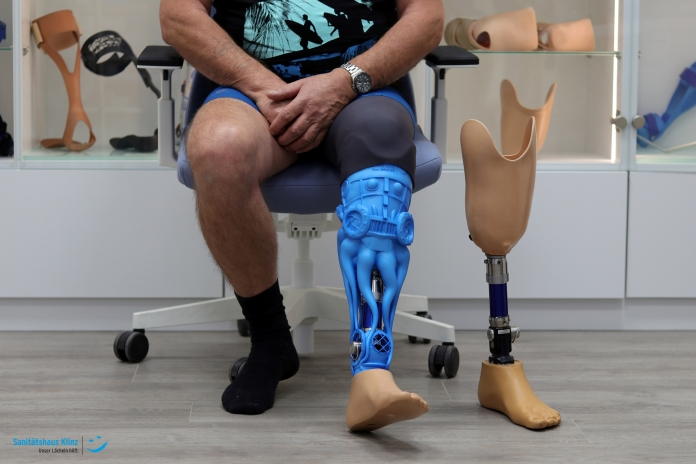
The patient with his new and old Sanitätshaus Klinz prostheses

One brisk morning in central Germany, Wolfgang K. climbed up into his delivery truck and set off on a new route, one that would prove to be the last of his career. His first stop was a hardware store, where he unloaded his shipment and waited for a forklift to carry the boxes away. Then tragedy struck.

Wolfgang was looking the other way when the forklift crashed into him, shattering his foot and knocking him to the ground. All he remembers from that moment is what felt like a slap on the back; then he blacked out. Sometime later, he awoke in unbearable pain, with paramedics around him, and was told about the massive damage to his foot and ankle.

The hospital treated and stabilized the immediate injury, but in the weeks and months ahead, the inflammation grew worse. Wolfgang begged his doctors to amputate his foot, but they weren’t giving up so easily. They did everything in their power to save it, for three years, until the inflammation had spread up his leg, triggering extensive tissue necrosis.

Wolfgang’s doctors were finally forced to amputate his leg below the knee. In the weeks following, after the swelling in the remainder of his leg (his residual limb) went down, Wolfgang was fitted with a transitional prosthesis. Around that time, he saw an advertisement for the Sanitätshaus Klinz orthopedics clinic of Bernburg, Germany, and soon after, he became their patient.

The staggering worldwide demand for prosthetics

With more than 185,000 lower limb amputations every year in the US alone, and over 1 million carried out worldwide, prosthetics specialists have struggled to keep up with the rising demand for their services.

The traditional method of creating prosthetic sockets, the part of the device that interfaces with the patient’s residual limb, involves plaster casting, hours of work, along with ample finesse and experience.

Although the specialists at Sanitätshaus Klinz still employ plaster casting and other analog methods in their work, for the most challenging of projects, especially those impossible to accomplish via traditional tools, they frequently turn to their 3D scanner Artec Eva.

A professional handheld 3D scanner that’s been a leading favorite among healthcare practitioners and thousands of others around the globe, the Artec Eva quickly delivers color 3D scans with a level of accuracy down below a millimeter, making it ideal for capturing the organic surface measurements of patients’ residual limbs and other body parts.

3D scanning the patient’s residual limb with Artec Eva and Artec Studio software

They also make use of the Artec Space Spider, for projects with intricate details that demand the utmost in precision. Originally developed for use on the International Space Station, the Space Spider is a popular choice among designers, engineers, and researchers in many diverse fields.

Dreaming up an entirely new prosthesis design

After having several prostheses since becoming a patient at Sanitätshaus Klinz, it came time for Wolfgang to get a new bath prosthesis, one that could be used in the shower or while swimming.

It would need to be both waterproof and corrosion-resistant, even in salt water environments. When Sanitätshaus Klinz’s biomedical engineer Lisa Pabst saw his request, she decided to offer him something even better.

From their discussion together, Pabst understood that Wolfgang’s great passion was diving. So, she, along with Wolfgang and her colleague master orthopedic technician Carsten Suhle, came up with the idea to create a unique bath prosthesis with a maritime design that wouldn’t merely be cosmetic, but rather to have the prosthesis itself be a one-of-a-kind, maritime-themed design object.

Even after losing his leg, Wolfgang had never abandoned his love for diving and the water. Once he heard Pabst’s idea, he enthusiastically gave her the green light.

Pabst spoke about the challenge of the project: “We wanted to pursue a different approach, to see whether it would be possible for us to integrate a prosthesis into our new design rather than adapting the design to an existing prosthesis.”

The new design, showing its ability to angle the prosthetic foot, for attaching a swimming flipper

Their goal was to combine all the water-resistant durability of a bath prosthesis with the esthetics of a cosmetic prosthesis, so when it’s being worn under long pants, no one can tell that there’s a prosthetic limb underneath. All the cosmetic elements of the prosthesis would need to cover and protect the mechanical components of the device.

Regarding the inspiration for the design, Pabst said, “We came up with the idea of using an octopus. The body of the octopus covers the upper part of the prosthesis, while the tentacles mimic the shape of the lower leg. A nostalgic diving helmet, entwined in tentacles, was added at the ankle. The ankle joint can be operated via the side openings of the helmet.”

The new bath prosthesis in use by the patient

At the same time, Pabst and her team understand that the most vital part of any new prosthesis is the shape and fit of its socket, with a design that’s unique to each individual patient, where even a mildly incorrect fit can often result in patient discomfort and biomechanical dysfunction leading to future injury.

At worst, an ill-fitting socket can cause a patient to suffer skin ulcers, impaired balance, falls, chronic musculoskeletal overuse injuries, osteoarthritis, and more.

To help achieve a seamless fit for the new socket, they turned to their Artec Eva, which Pabst used to scan all of the surface geometry of Wolfgang’s residual limb in less than a minute. Pabst also scanned his other leg, in order to use its precise volumetric and surface measurements for creating the shape and dimensions of the new bath prosthesis.

Artec Studio screenshot: an Eva scan of the patient’s residual limb

Right after the scanning session, prior to exporting the 3D meshes to Geomagic Freeform, the scans were processed in Artec Studio software. Using the intuitive tools within the software, Pabst deleted any unwanted data, including the floor and other objects around.

Artec Studio screenshot: an Eva scan of the patient’s contralateral leg

The scans were aligned and registered, then merged together into one object. Finally, the texture was brought in and applied to the mesh. In Freeform, Pabst designed the prosthetic socket and sculpted the cosmetic elements of the design to life.

Pabst commented on how instrumental their Eva has been, in synergy with Freeform: “When I import an Eva scan into Freeform, I’m starting off with a dependable foundation for my prosthetic design work. It takes only seconds for Eva to capture the exact measurements of a patient’s body, and in Freeform, I build my new designs based on these same dimensions.”

Geomagic Freeform screenshot: an Eva scan of the patient’s contralateral leg & an Eva-scan-based model of his residual leg

Pabst continued, “Particularly when creating a new prosthetic socket, which must perfectly embrace and support the unique shape of a patient’s residual limb, every millimeter of surface should be digitally captured and brought into the design. Fortunately, the Eva does this quickly and easily.”

Her workflow included the following steps: after importing and arranging the meshes in Freeform, she modeled Wolfgang’s residual limb. Then, before moving on to the subsequent steps, she mirrored his contralateral leg in Freeform. From there, she built up the prosthetic shaft, shaping it to the adapter and preparing the design for the functional elements.

Geomagic Freeform screenshot: Shaping the shaft to the adapter, and adapting the design to the prosthesis’ functional elements

Pabst then shaped the outer dimensions of the tentacles in accordance with the exact measurements of Wolfgang’s other leg, to achieve the same overall circumference of the lower leg.

Geomagic Freeform screenshot: Shaping the dimensions of the tentacles using the Eva scan measurements of the contralateral leg

At this point, Pabst created the tentacles’ suction cups, then connected the shaft, octopus, tentacles, and diving helmet. After several other steps, she embossed the design with the Klinz logo and the patient’s name.

After 3D printing the exterior components of the new prosthesis, they were merged with the mechanical elements of the device and locked into place. That’s when Wolfgang was invited to the clinic for his fitting.

Standing proudly: the new bath prosthesis in place and ready for use

From the moment he caught sight of his new leg, he’s been very happy with it, while the fit is as comfortable as he has come to expect from using his other Klinz prosthetic devices. His wife and daughters are delighted with it as well. On a recent vacation to the Baltic Sea, children wandered over to get a closer look and admire his amazing leg.

The power and potential of 3D scanning in O&P

Pabst commented on the pivotal role that 3D scanning has gained in modern orthotics and prosthetics design, “Whenever you need to create an orthosis, or an upper- or lower-body prosthesis, with high-tech or low-tech materials, first you absolutely must have accurate measurements of the patient’s body where the new device will connect.”

Using a haptic device with Geomagic Freeform to put the finishing touches on the new bath prosthesis

She explained further, “Without this foundation to build on, eventually serious problems will arise, from the fit of the device, to the patient’s physical responses to it, etc. By starting off with Artec scans, every device we produce looks exactly like the other side and a natural extension of their own body. The difference this has made in our work is truly significant.”
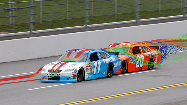
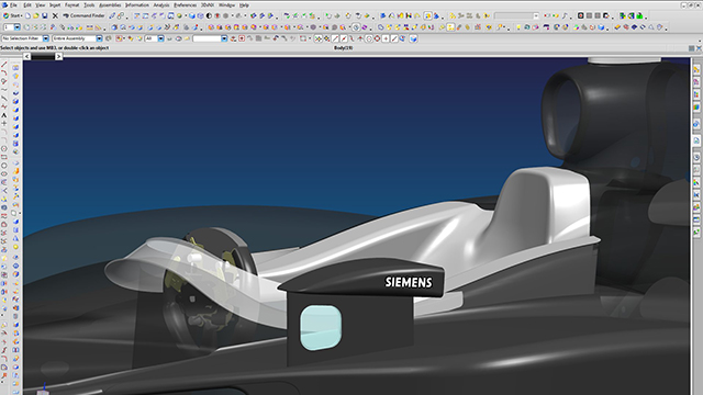
Andretti Autosport, Hendrick Motorsports and Joe Gibbs Racing speed software learning curve using online tools

Product: NX CAM
Industry: Automotive and Transportation

It’s all about speed

Speed is the essence of auto racing. The first car to the finish line wins, so it is the responsibility of every crew member – including those who work at team headquarters designing and building parts and systems – to do whatever they can to help make the cars go faster. Engineers, designers and machinists work year-round, improving and refining their team cars’ engine and drive train performance, fabricating parts and systems, and responding to rule changes from racing governing bodies, such as IndyCar and NASCAR.

Siemens PLM Software helps racing teams achieve their goal of making cars go faster by providing a variety of tools to help users get up-to-speed on using its software systems, including Learning Advantage, an Internet-based learning management system. Learning Advantage is a convenient, easy-to-use e-Learning portal that provides cost-effective and time-efficient methods for users to gain skills and knowledge of Siemens PLM Software solutions. This system provides access to an unparalleled library of self-paced courses and assessments, as well as management tools for companies to measure learning progress and to administer learning programs.

When you can’t get to a class right away

“Hectic racing schedules can make it tough to attend traditional classroom training,” says Scott Graves, Engineering Operations Manager at Andretti Autosport™, an IZOD IndyCar Series™ team. “Learning Advantage has made training possible even in the middle of the racing season.”

“Sometimes new employees will not have an opportunity to attend a class right away based on course or workload schedules, and Learning Advantage will get them up-to-speed until a live course is available,” says Jon Rittle, engineering designer, Vehicle Dynamics Group at Joe Gibbs Racing, a NASCAR team. “Learning Advantage is also great for advanced CAD (computer-aided design) users who are familiar with other systems, but new to NX™. They can pick and choose the courses that will benefit them the most. And it’s always there to go back to as a refresher, or reference tool.”

Hendrick Motorsports, another NASCAR team, has similar experience with Learning Advantage. “We use Learning Advantage almost daily,” says Jim McKenzie, engineering applications manager at Hendrick Motorsports. “All of our licenses are in use constantly.”

Racing teams often field multiple cars in each race, and the lifespan of an engine is usually one race or less. So, shop crews are constantly fabricating parts and building new engines for their own teams, and in the case of Hendrick Motorsports, building engines for other teams. Over the course of a season, racing teams build hundreds of engines, not to mention numerous other car parts and systems.

Program expansion and new hires create an ongoing need for training. “As employees are promoted throughout the company, and we hire new employees, the need arises for more training,” says Rittle. “Like a lot of companies, we haven’t the resources that we would like to have, so we try to schedule our in-house ‘core functionality’ training classes quarterly, when possible. That said, there can be a gap in time from when a training need arises and when the next scheduled class is available. At times like this, we leverage the capabilities of Learning Advantage to help get users up-to-speed and proficient in their daily duties, and to prepare them for the in-house training classes when they become available.”

A continuous need for training

Even trained users need additional training. “Several of our engineers are occasional users and online training enables them to quickly brush up on features that they haven’t used recently,” says Graves. “They can also broaden their skills at their own pace.”

Training can help users renew their skills, as well. Graves notes, “Recently we hired a new designer who had been away from NX for several versions. He easily picked up with the current version using online training as a refresher course.”

Teams also have to train the trainers. “We are constantly looking to upgrade and expand into new areas of the software,” says McKenzie, “This creates a need for more training as well. Obviously we need to ‘train the trainers’ as well as our end-users, so having the Learning Advantage and course material tools available to us is a huge advantage.”

Rittle can relate. “Learning assembly sequences was a big one for me,” he says. “Suddenly, I was able to put the engine internal systems in motion and check clearances and fit-ups much quicker. It was exciting to see the parts animated. Learning Advantage was very helpful for freeform modeling. It helped explain the differences between different types of surfaces quickly, and how I could create them. I was learning it at the same time I was using it for creating complex parts. Without Learning Advantage, it would have taken much longer with less impressive results.”

“If you’re in a hurry and need some guidance to get you through the job on time, either because you’re using a new area of NX, or just haven’t used it in a long time and need a refresher, Learning Advantage is a great tool to have,” Graves says. “You can quickly zero-in on your area of interest and see how NX can help you in a rather quick time frame, using hands-on examples and not just by reading a menu of instructions. It allows us to get changes and new ideas to the track faster, helping to improve our performance every race weekend.”

“Siemens PLM Software training is very important early-on to employees’ tenures,” says Rittle. “It reduces time spent trying to do something they might have done differently on another system in the past, or have never done before. There are many ways to get the same result in NX, and the courses can help explain the best method for a particular task.”

The bottom line of applying Learning Advantage is that it provides a real advantage in keeping the racing teams as productive and creative as possible. “Every minute that we are able to train in-house and not traveling to an off-site training facility is another minute that we can apply to making the cars go faster,” McKenzie says.

Finnish Jeweler Gains Productivity and Flexibility with 3D Systems Wax 3D Printing Solution

Product: MJP
Industry: Consumer Products and Retail

Narsakka, a traditional Finnish goldsmith company, has adopted 3D Systems’ solution for 3D printing wax patterns for direct jewelry casting. Developed to produce jewelry casting patterns that fit into standard lost wax casting processes, the addition of this 3D printing solution has helped Narsakka increase productivity with consistent quality outcomes and maintain better design and production flexibility to answer evolving customer demands.

“With the quality of the wax material we print with, we get a 100% success rate – every part comes out perfect.”

– Thomas Narsakka, Manager at Narsakka

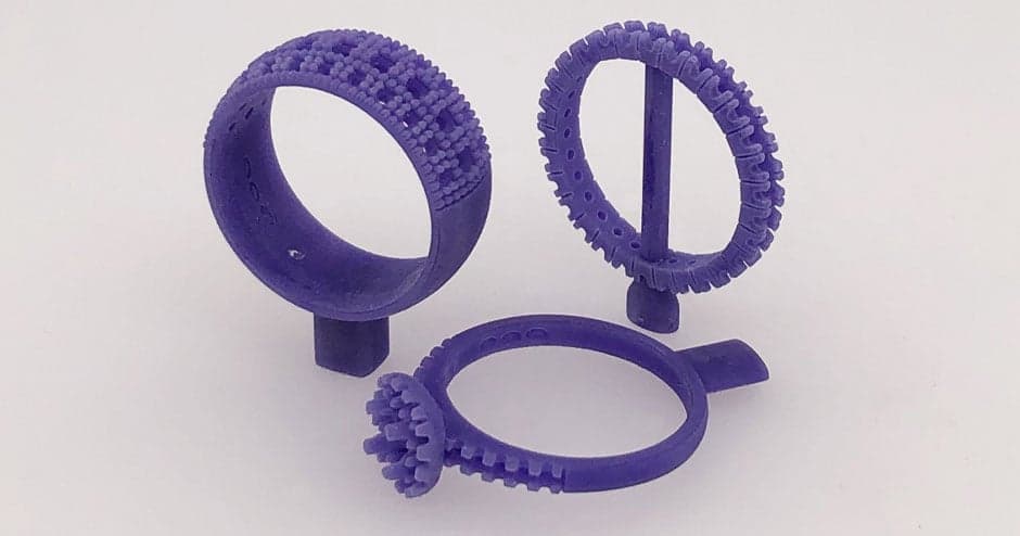
3D printed jewelry casting patterns produced in pure wax on the ProJet MJP 2500W

CONSISTENT QUALITY AND PRODUCTIVITY IN JEWELRY MANUFACTURING

Lost wax casting is a trusted method of jewelry production that yields beautiful, high quality results. However, traditional methods of producing the sacrificial wax patterns are time consuming and labor intensive. Traditional processes have multiple stages that invite the possibility of error, increased costs, and delays. By transitioning to 3D Systems’ jewelry wax printing solution, one of Narsakka’s goals was to remove this variability to ensure better quality outcomes.

Changing consumer habits also motivated Narsakka to transition to a digital jewelry workflow. In response to the abundance of options the average consumer can find online, Narsakka’s retailer customers have changed their purchasing behavior, placing smaller orders in only a few sizes and making up the difference with on demand production as needed.

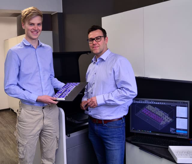
Owner of Narsakka OY with 3D printed wax casting patterns

Narsakka is taking advantage of 3D Systems’ jewelry manufacturing solutions.

01 EXPERT PARTNER CONSULTANCY

Narsakka was familiar with 3D technologies from having used 3D design software for more than 20 years. To tap into the prototyping and production side via 3D printing, Narsakka used 3D printing services to test the waters. Once the digital workflow had been proven, Narsakka partnered with PLM Group, part of 3D Systems’ authorized reseller network of experts, to implement its own in-house solution. PLM Group has 20 years’ experience helping its customers build capabilities to deliver high quality products faster, better, and more cost-effectively.

“We realized that there were 3D printers on the market that could match our demands for build size, printing speed, and quality,” said Narsakka. “As we had prior knowledge in 3D printing, it was an obvious choice for us, not least when we saw that we could produce hundreds of wax parts in a couple of hours.”

02 PURE WAX 3D PRINTING

Casting pattern quality is a key success factor in the quality of the final casting. 3D Systems’ ProJet® MJP 2500W 3D printer prints in 100% wax and was developed to produce jewelry casting patterns that fit into the standard lost wax casting process. Combined with the pure wax VisiJet® M2 CAST material, this digital workflow solution consistently delivers true-to-CAD fidelity and fine feature definition jewelry patterns with 100% ash burnout. The smooth surface and sidewall quality enable a faster pattern-to-finished piece workflow with less handwork, helping Narsakka reduce lead times from weeks to days for more efficient iteration and production.

“It’s […] easier for us to calculate lead times and production cost. 3D printing basically gives us more control of our business.”

– Thomas Narsakka, Manager at Narsakka

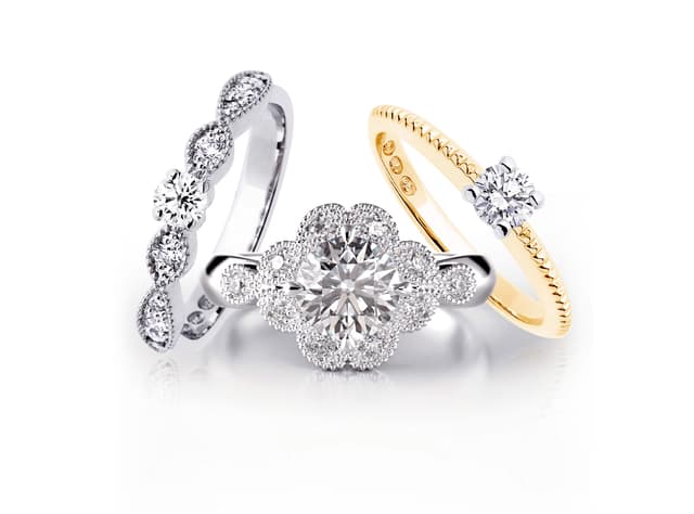
Final rings produced by Narsakka

The flexibility of 3D printing solution helps Narsakka tailor its offering to match customer demand.

03 STREAMLINED FILE-TO-PATTERN WORKFLOW

Narsakka is taking advantage of 3D Systems’ end-to-end jewelry workflow, which spans from software to printer to post-processing operations. 3D Sprint® software offers advanced capabilities to streamline the file-to-pattern workflow with tools for print file preparation and optimization, including automatic support generation, and optimized part placement to maximize the productivity of the build with high volume batches. 3D Systems’ jewelry solution uses dissolvable and meltable supports, enabling batch support removal for quick access to ready-to-cast patterns. In just four hours, Narsakka can produce 60-100 wax parts, which has shortened its lead times dramatically – from weeks to days.

04 FLEXIBLE PRODUCTION

In addition to using the ProJet MJP 2500W for high volume production batches, Narsakka is taking advantage of the ability to offer mass customized options and implement on-the-fly design changes. In this regard, the company has found its digital workflow to be perfect for shorter runs and more specialized production of bespoke jewelry. “Nowadays, customers want more specific items, and have more individual tastes,” said Narsakka. Because of the flexibility of its 3D printing solution, the jeweler is now able to tailor its offering to match customer demand, which has opened up new business opportunities along with unlimited design possibilities for the most creative styles.

Starburns Industries Uses 3D Printing to Bring Greater Realism to Anomalisa Character

Product: CJP
Industry: Design and Art

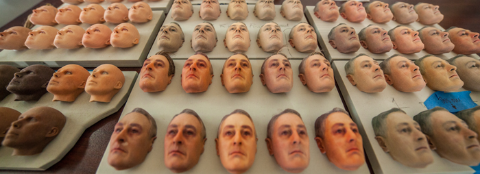
Starburns Anamolisa CJP Printed Faces

Aesthetic Value Meets Productivity
Over the last few years, 3D printing has become commonplace in the movie industry for applications such as prototyping, prop making and creating objects that are difficult to construct in traditional ways. But, in the sheer volume of parts and in the emotional realm in which it is used, Anomalisa sets new precedents for 3D printing in entertainment.

Duke Johnson, co-director of Anomalisa, along with Charlie Kaufman (Being John Malkovich, Eternal Sunshine of the Spotless Mind), cited 3D printing for helping to establish the inner feelings of the characters and providing a higher level of detail.
But for all the aesthetic value that the ProJet CJP 660 helped bring to the characters, the use of this particular 3D printer came down primarily to productivity: the system is fast, reliable and generates life-like color. 

Starburns Anamolisa CJP FiguresThe ProJet CJP 660 outputs full-color 3D prints in one run without having to change palettes. Its build area of 254 x 381 x 203 mm (10 x 15 x 8 inches) enabled Starburns to turn out dozens of faces with different expressions in a single run within hours.
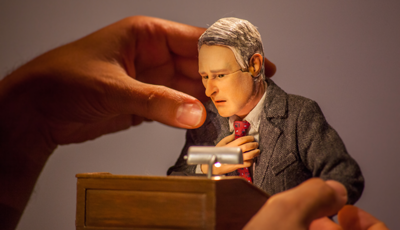
“Color is the most important attribute for us, along with speed and the volume the machine can produce,” says Bryan LaFata, Operations Supervisor at Starburns Industries. “We were running the ProJet almost non-stop for a year and a half during Anomalisa production, creating thousands upon thousands of faces.”

Thousands of Expressions   
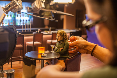
Starburns modeled and printed three basic head designs for Anomalisa: One each for the lead characters Michael and Lisa, and another for what is called the “world face,” a composite face modeled from 20 or more Starburns employees. The world face was used for every character except Michael and Lisa.

Starburns Anamolisa CJP FiguresThe faces for the characters include an upper and lower faceplate. Thousands of expressions were modeled and printed by Starburns for the characters. This gave animators access to nearly every possible expression for a given scene.
“We produced racks full of faces so they could be switched out at any time,” says LaFata. “It could take multiple facial models just to get the right smile.”

Retaining the Look and Feel  
A conscious choice was made by the Anomalisa directors to keep the lines between the upper and lower faces in place without digital airbrushing.

James A. Fino, Executive Producer and Partner at Starburns, explains this decision in an article on the Producer’s Guild of America website: “Recent stop-motion animated features typically erase those lines digitally, but that was not our choice for Anomalisa. Rather than a distracting element, the seams serve as subtle and persistent signs of the incredible artistry on display in the film.”

In a New York Times article by Mekado Murphy, co-director Kaufman explained it this way: “We didn’t want to hide the fact that it’s stop-motion. We didn’t want to paint out the thing that it was…we wanted that feeling of the unseen presence of the animators.”

Starburns also did minimum post-processing of the characters’ faces, retaining the look and feel that came directly from the ProJet 660. Again, this was the directors’ preference.

“We used [3D printing] for a very specific purpose with the realism that they wanted in the faces, and the textures and the differences in color would not have been possible by hand-painting,” says Caroline Kastelic, Starburns Puppet Supervisor, in an IndieWire interview. “And that’s why they have that nice texture on them…I find that aesthetically brilliant and it also saved us a lot of time.”

Local Support 
Creating the thousands of faces, dozens of body models, and the realistic sets for a production such as Anomalisa takes teamwork; not just among the nearly 200 people at Starburns, but by outside partners as well.

LaFata gives credit to 3D Rapid Prototyping, a 3D Systems partner based in nearby Garden Grove, California, for keeping Starburns supplied with materials and even printing face models when needed.

“We were pushing out a lot of faces, often 24/7, and Bill Craig [3D Rapid Prototyping President/CFO] and his team were always there to help us out,” he says.

Big Future for 3D Printing 
No matter how fascinating the behind-the-scenes technology is for a film, the ultimate measure of success is how the story is delivered. In the case of Anomalisa, 3D printing is not just a special effect or quirky conversation piece; it is integral to the way the characters perform.

The approach seemed to have struck a chord: Beyond Oscar and Golden Globe nominations, Anomalisa was the first animated film to win the Grand Jury Prize at the 72nd Venice International Film Festival. In his five-star review in Rolling Stone magazine, Peter Travers calls Anomalisa a “stop-motion masterpiece.”

Bryan LaFata doesn’t think Anomalisa is a one-off phenomenon.

“The scale and speed at which you can produce full-color models on a machine such as the ProJet CJP 660 is definitely a major benefit,” he says. 

“I think 3D printing has a big future for stop-motion films.”

“It’s the largest object we ever scanned!” Artec 3D scans gigantic gas engine in Luxembourg

Product: Artec Leo
Industry: Industrial Machinery and Heavy Equipment

Modern, professional-grade 3D scanners can capture all kinds of objects – from tiny things such as a screw or a human tooth to much larger and more complex objects including vehicles, rooms, or even entire buildings. You can use them from the comfort of your own desk, or take them to remote, faraway places – even those with no electrical outlets or internet connections.

It hasn’t always been this way, though. Until very recently, 3D scanners could only be used indoors, under certain lighting conditions, with a steady power source and powerful computer. They were often bulky and heavy, making them difficult, if not impossible, to maneuver while scanning. Most significantly, such scanners could only capture objects of limited sizes – something that could fit on your desk like a sculpture bust, or a flower pot. Anything larger was either too difficult, too time-consuming, or simply impossible to scan.

This was the situation the team at the Luxembourg Science Center found themselves in back in 2016 when they decided to digitize one of Luxembourg’s national monuments called “Groussgasmaschinn” – the world’s largest blast furnace gas engine. To find the best possible way to capture an object as big as this, they reached out to the 3D scanning experts at Artec 3D headquarters in Luxembourg.

Gas Engine #11

Built in 1938 by Ehrhardt & Sehmer, the Groussgasmaschinn is the largest gas engine ever built

Built in 1938 by German manufacturing company Ehrhardt & Sehmer by order of a Franco-Belgian consortium called “Hauts-fourneaux et Aciéries de Differdange, St-Ingbert & Rumelange” (HADIR), the Groussgasmaschinn is so large it could contain an entire tennis court, and then some. It is 26 meters long, 10.5 meters wide, and 6.5 meters high, weighs 1,100 tons, and was able to produce 11,000 horsepower, or up to 7000 kilowatts. It has four cylinders, each of which had a capacity of 3,000 liters, and an 11-meter and 150-ton flywheel, which rotated at 94 RPM. The engine was operated by 12 workers per shift, and during its lifetime (1942-1979) produced more than 6,000 kW of power from blast furnace gas (a waste product generated by the combustion of coke fuel in blast furnaces).

The Groussgasmaschinn in the Differdange Gas Plant in 1940. Photo courtesy of the Luxembourg Science Center

Located in Differdange, Luxembourg’s industrial town 27 kilometers southwest of Luxembourg City, in a former steel production plant currently owned by world-leading steel and mining company ArcelorMittal, this 1,100-ton industrial masterpiece stands as the last witness of a once booming, now bygone era of the Luxembourg steel industry.

It was one of 14 other gas machines of various sizes and horsepower installed in the Differdange Gas Engine Plant between 1896 and the 1940s, with the Groussgasmaschinn being the largest. The engine was installed and put into full operation in May 1942, two years after the Grand Duchy of Luxembourg was occupied by Germany during World War II. Despite the Nazi occupation, there were no service interruptions, bombardments, or explosives planted in the vicinity of the Gas Plant throughout the entirety of the war. And at the end of the war, the gas engine was left intact.

The engine was not only the largest ever built, but probably one of the last ones as well, due to the emergence of more efficient and readily available steam turbines. After its shutdown in 1979, the Groussgasmaschinn remained abandoned for nearly 30 years. It came back from the brink of oblivion in 2007 when Luxembourg’s Ministry of Culture designated it as a National Monument worthy of preservation and restoration. Thanks to the support of the Groussgasmaschinn Association (further evolved into the Luxembourg Science Center) and a privately held firm called “GGM11” that served as the project’s sponsor, restoration work began five years later, in 2012, and is still ongoing.

It was during this time that the Center developed the idea not simply to restore the gigantic engine back to its best shape, but also to digitally preserve it for future generations. In 2016 they reached out to Artec 3D in Luxembourg, but even the best of the scanning technology available at the time wasn’t able to capture something this huge. Fast forward a few years, and with new 3D scanning options developed and available, Artec was ready to scan an object as massive as this.

“We’ve been meaning to scan this engine for a very long time, and we’re glad that the technology is finally here to help us do it. There is no other gas engine like this one, and it’s crucial to capture it in its current state,” said Nicolas Didier, President and General Manager of the Luxembourg Science Center.

“This data can not only help us with the restoration process by being able to recreate some missing parts and elements out of 3D scans, it also is a great way to showcase GGM11 to our remote visitors as well as demonstrate the potential of such innovative technologies as 3D scanning, which we’re planning to introduce and teach at the Center later this year.”

Scanning Big

“It’s the largest object we ever scanned! And much bigger than I expected,” said Vadim Zaremba, Deployment and Technical Support Engineer at Artec 3D, when he first visited the Gas Plant to assess the scope of future work in November 2020. After examining the gas engine and passing all the required security procedures in early 2021, Vadim returned to the Gas Plant with his colleague, Technical Support Specialist Raul Monteiro, and all the necessary gear.

As in most cases, the size and complexity of the object determines the scanners to be used. Artec Ray was chosen as the primary scanner for capturing the entire engine, due to its ability to scan large objects from a distance with submillimeter accuracy, while the Artec Leo, a wireless, portable 3D scanner, was chosen as a second device, specifically for capturing high levels of detail from the smaller parts and sections of the engine.

“GGM11 is not only the largest object we ever scanned, but it’s also a very complex one,” added Zaremba. “It has many cavities and hard-to-reach places, that’s why having two scanners that could capture both the entire machine and its smaller parts in high definition (and with two people operating them) was essential.”

The size and complexity of the object determined the scanners to be used: Artec Ray and Artec Leo

The plan was, first, to scan the engine with Ray from as many angles as possible, to capture the entire object, and then go back and scan any missing, smaller, hard-to-reach sections with Leo. Because Ray was scanning at maximum resolution (point density), to save some time, the team decided to split up. Zaremba was positioning Ray at various locations, at one particular angle, 5 to 15 meters away from the engine, while Monteiro was scanning smaller sections of the engine (which weren’t in Ray’s field of view) with Leo. Then Zaremba moved on to the next spot, and Monteiro followed behind, along the same route.

While Ray silently scans the engine, Zaremba steps away for a minute or two of scanning smaller sections up close with Leo

One of the most challenging tasks was that of scanning the engine from above. To accomplish this, the team had to climb a special bridge built in the 1940s-1950s, which features a cabin hanging 10 meters above the floor, as this was the ideal spot for scanning the engine from multiple angles. This was easier said than done. The bridge was old and unstable, and under the weight of two people plus a 3D scanner, such a foundation was not conducive to creating high-quality scans. To ensure that the scan data was flawless, Zaremba and Monteiro had to remain completely still for several minutes while the scanner did its job.

Overall, it took the team four working days to complete the project, with three-to-four-hour shifts of active scanning every day. The engine was scanned from 18 different angles with Artec Ray, and these were later combined in Artec Studio with 67 more scans made with Artec Leo. The final size of the project came to 186 GB in total, with 170 GB of Leo scans and 16 GB of Ray scans.

Powerful processing

Processing an object as big as this was a challenge in itself. To make sure all the data was processed correctly, Artec 3D Tech Support Engineer Dmitry Potoskuev split up the process into several batches:

He started with Ray data first. He cleaned up the data by removing all the unnecessary objects that the scanner picked while scanning the engine (using the Eraser tool), such as parts of the Gas Plant building, windows, walls, and various other equipment around the GGM11.

Then he focused on unifying the flywheel and other parts data across all 18 scans by erasing specific data from some frames using the Eraser tool. This was necessary because several scans were done on different days, and the position of the flywheel and a few other parts changed a few times when the engine was turned on by GGM11 staff for demonstrations. This could result in some mismatches if those scans were simply merged together as is.

Following that, all Ray scans went through Global Registration to be registered between each other. Then each of 18 scans were processed into meshes using the “Ray scan triangulation” algorithm with Polygon edge length (max) at 10 mm. This was done to filter all the surfaces with a large distance between the vertices, and as a result, to get a more detailed and clean surface afterwards. After that, all the 18 triangulated meshes were processed using Sharp Fusion algorithm to create a single mesh aka “skeleton” of the engine’s model.

The next step was to add all the details captured with Leo. Because of the size of all the data (170 GB), Potoskuev broke the process down into several steps.

First, he duplicated and locked the original Ray mesh. The duplicated copy was simplified to 5-10 million polygons and locked too. This was done to fasten the further registration process. Next, he uploaded all Leo scans (divided into 17 groups during scanning) to the duplicated Ray project, and each of them was registered with the separately simplified Ray project for higher-quality alignment of data.

After all the Leo scans were registered, Potoskuev selected the original Ray mesh and 4-5 raw registered Leo scans, and applied the Sharp Fusion algorithm to create a new mesh. He repeated the process until all the Leo scans were processed with the original Ray mesh into a final mesh of the gas engine.

The final mesh consisted of around 350 million polygons, which were then reduced to 10 million polygons for further post-processing, using such features as Hole Filling tools, the Smooth Brush, and Bridges. The total processing time for the largest gas engine ever built? All done within two weeks, or 80 hours of actual time.

Speaking about some of the challenges he faced while working on the model, Potoskuev said, “Time was definitely the greatest challenge. This project was so big, not only did scanning and processing take a long time, but transferring the data from the scanners to the computer, and then into Artec Studio, could take up to as much as 5-6 hours…just for transferring! We’re talking about almost 200 gigabytes of data – it’s the largest and most time-consuming object we’ve processed, for sure.”

But as with the best things, patience pays off. “I’ve never worked on a project as massive as this,” said Potoskuev. “It’s amazing that with the 3D scanning technology we have today, something so vast and inaccessible has been digitized right down to its finest details.”

From 1940s all the way to 2020s, the Groussgasmaschinn got a second breath thanks to the power of 3D scanning technologies

The final result

While this massive task is now complete, the engine’s story is far from over.

“With this gigantic engine 3D scanned, we can use this data to restore some missing parts and preserve it in its current state, so even if it loses its shape with time, we can still go back to this 3D model and show it to our future visitors, and use it for restoration purposes,” said Nicolas Didier, President and General Manager of the Luxembourg Science Center.

“We hope to finish the renovation of the engine by 2027-28 and make it an integral part of the Science Center, one of the interactive stations that our visitors can not only see, but interact with as well. And with the two Leos that we purchased earlier this year for our Future Skills program, our students and staff will be able to 3D scan it on their own!”

How a mountain bike enthusiast designed and manufactured his custom carbon fiber bike from scratch with Siemens NX

Product: NX CAD
Industry: Academic

Siemens is not only offering products to big companies, but also small and medium businesses and even private persons can subscribe and benefit from the Siemens Xcelerator portfolio of software and services. This is what this case demonstrates:

We recently found out about the project completed by a German mountain bike enthusiast, who calls himself Uncle Bob, and his journey that started with an empty screen and ended with custom self-built carbon fiber mountain bike.

Uncle Bob’s journey

Due to an injury from biking, Uncle Bob needed a new project to keep himself entertained. He is the founder of an engineering consultancy, which is why he owned the Siemens NX CAD software and has experience with it. So, in his free time he just started directly scribbling in Siemens NX with a try and error approach and with the following weeks, his ideas became a solid concept. 

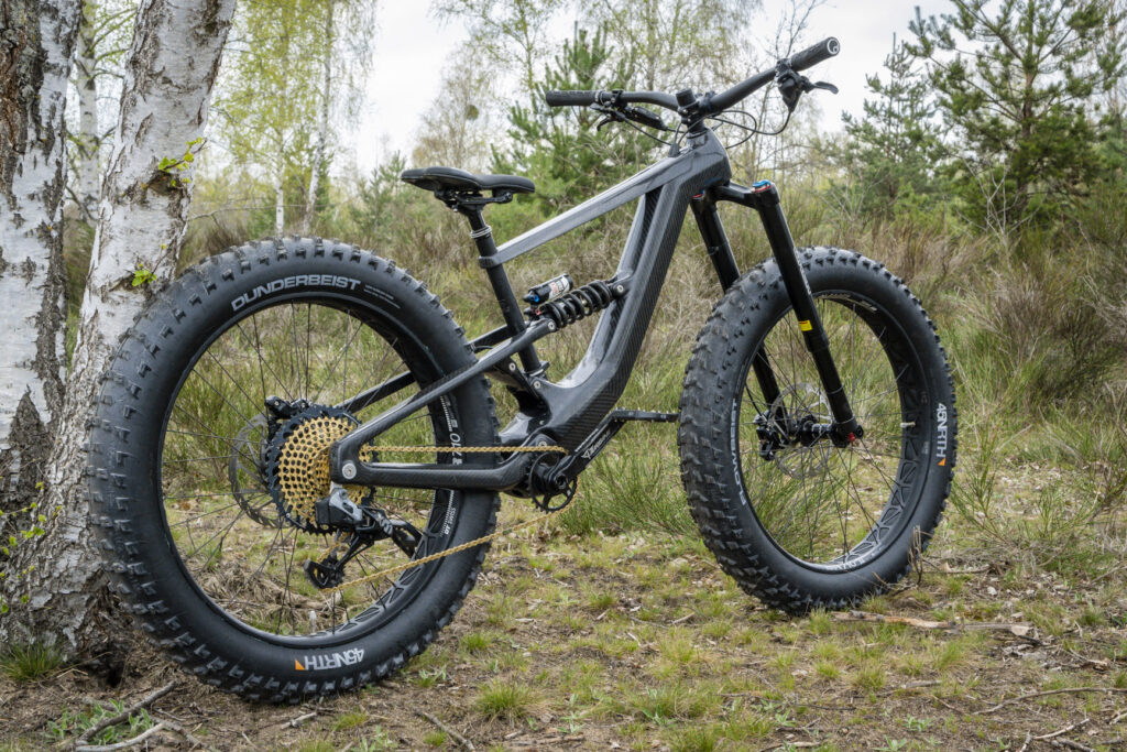
mountain bike in forest

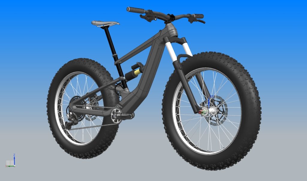
Bob was especially delighted with the plentiful and individual 3D visualization options NX had to offer, they enabled him to work creatively and to see the realistic result of his design before building. 

Considering the design, Uncle Bob has gone for a form follows function approach: “If something already looks like something that will not last, it surely will not last during tests.” 

Why NX?

Apart from the design aspect, he really appreciates NX for the ability to test and verify his CAD design data into finite element analysis (FEA) simulation tools, which he uses in his daily professional life as well as with this bike. “I have not regretted the investment for Siemens NX, it was worth it and definitely helped me to ease up processes. Before NX, I had to copy data manually from program to program. The implementation of NX at Daimler got me starting to look out for better solutions.” 

bike model inside of nx

So, an FEA study was done to stress test the frame and structure. After all, mountain bikes like these need to withstand high physical forces due to big jumps, loose ground and high speeds. And his bike did!

For example, his calculations resulted that the frame around the bottom bracket can withstand jumps or falls with more than 6,000N. For the areas that failed his tests, the layup of the composite material was modified in Siemens NX and additional plies were added to strengthen these areas.

Getting started and getting building with NX

bike model mold

With a flaw free concept ready, he designed an injection mold in Siemens NX that he could use for producing the carbon-fiber parts. Due to the extensive 3D features in Siemens NX, he could make the mold as material efficient and small as possible.  Then he started working in his garage: A wax core was casted that represents the inner geometry of the carbon frame. Then, he wrapped the carbon fiber around it and closed the mold airtight. Using vacuum and high pressure a hardening resign was injected into the mold. After a few hours of tempering the resign was hardened and with higher temperature the wax core melted and flowed out. Now the frame was made. He didn’t clearcoat the frame because Uncle Joe was confident enough that his construction and his materials used were sufficiently durable anyway.

After that, the frame was made and he started to assemble all the custom frame parts and bought standard parts together. A few weeks later it was all done, a extreme mountain fat bike, that all-in-all only weighted 17kg, with the NX constructed custom carbon forged frame only taking 3kg part of that. After his first test ride, Bob was beyond impressed:

“Insane! Sore muscles in the face because of the permanent grin. I can only say: Dreamy. The bike fits me like a glove.”

Alpine F1 Team Advances Energy and Fluid Management with Titanium Printed Hydraulic Accumulator

Product: DMP Flex 350
Industry: Automotive and Transportation

Alpine F1 Team turned to metal additive manufacturing (AM) to push the performance of its car by producing a titanium hydraulic accumulator with complete functionality in a minimized footprint. With years of collaborative supply and development with 3D Systems, Alpine F1 Team selected 3D Systems’ direct metal printing (DMP) technology to produce the complex part, and relied on 3D Systems’ expertise and proprietary cleaning processes to ensure optimal quality. 

“Beyond the necessary accuracy of the part itself, we had very strict fluid cleanliness requirements for the inverter coil that could only be achieved by partnering with 3D Systems. Their proprietary cleaning process has a proven track record in high performance applications for delivering particle-free components, even on challenging internal channels.” 

 – Pat Warner, Advanced Digital Manufacturing Manager, Alpine F1 Team 

PUSH PERFORMANCE WITH ADVANCED DESIGN AND MANUFACTURING

Alpine F1 Team is continually improving its car, working in very short iteration cycles to advance and refine performance as much as possible. Constant challenges include working within the limited space available, keeping part weights as low as possible, and adhering to evolving regulation constraints.  

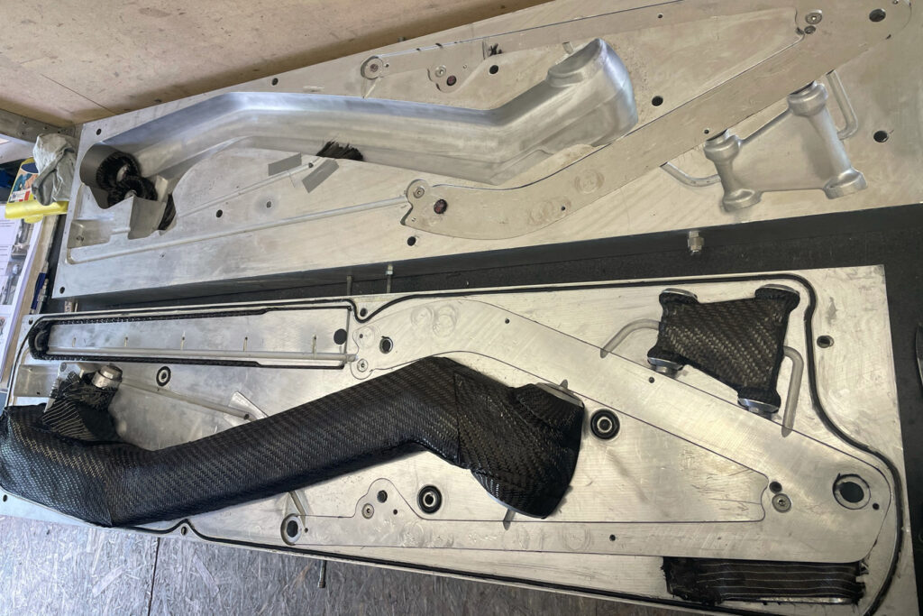
Experts within 3D Systems’ Application Innovation Group (AIG) provided Alpine F1 Team with the know-how to make titanium production possible for a complex coiled component with a challenging, function-driven internal geometry. Additive manufacturing offers a unique opportunity to overcome the challenges of fast-paced innovation by supplying highly complex parts with short lead times. For parts like Alpine F1 Team’s hydraulic accumulator, additional AM expertise was required for a successful part due to the level of design complexity and strict requirements for cleanliness.  

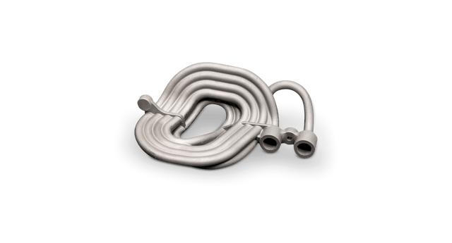
Metal 3D printed inerter coil designed by Alpine F1

Additive manufacturing enabled the Alpine F1 Team to maximize the length of the dampening coil while packaging complete functionality within a restricted space.

The Solution

01 Packaging Complex Functionality in a Limited Space

For the accumulator, specifically a rear heave fluid inerter coil, Alpine F1 Team designed a hard-line damper, which is part of a rear heave damper in the rear suspension system inside the gearbox main case. A long, rigid piece of tubing, the accumulator stores and releases energy in order to average out pressure fluctuations. As such, the performance of the line damper is correlated to its internal volume, and thus the length of the component. 

Additive manufacturing enabled the Alpine F1 Team to maximize the length of the dampening coil while packaging complete functionality within a restricted space. According to Pat Warner, Advanced Digital Manufacturing Manager at Alpine F1 Team, the final design would be impossible to produce using any other method: “We designed this part to be as volumetrically efficient as possible, and to share wall thickness between adjacent tubes. Achieving this volume is only possible with AM.” 

The final titanium dampening coil was produced using 3D Systems’ DMP Flex 350, a high-performance metal AM system featuring best-in-class oxygen levels (<25 ppm) and an inert printing atmosphere. The unique system architecture of 3D Systems’ DMP machines ensures exceptionally strong and accurate parts with high chemical purity, and the repeatability needed for production parts. 

02 Part Cleanliness for Flawless Performance

During operation the dampening coil is filled with fluid and averages out pressure fluctuations within the system by absorbing and releasing energy. In order to function properly, the fluid has a specification for cleanliness to avoid contamination. Using metal AM to design and produce this component offered considerable benefits in terms of functionality, integration into the larger system, and weight reduction, yet the team faced a challenge when it came to complete powder removal from the internal channels.   

To achieve thorough material evacuation on these complex metal prints 3D Systems’ AIG contributed its vast process knowledge to apply a proprietary cleaning protocol that has been successfully used on to tens of thousands of parts, and ensures particle-free titanium components. For customers who plan to adopt metal AM and require the highest degree of part cleanliness for internal channels, 3D Systems has an established protocol to transfer this know-how to new facilities. 

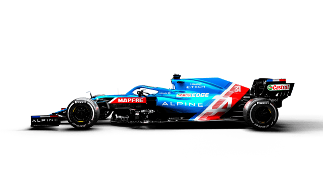
Alpine F1 race car

Alpine F1 Team works in very short iteration cycles to advance and refine the performance of its car as much as possible.

03 Quality Metal Workflow

3D Systems’ complete metal AM solution goes beyond its leading expertise and metal printing platform to include carefully developed and optimized materials and 3DXpert software. 3DXpert is an all-in-one software for preparing, optimizing, and managing the metal printing workflow.  

Alpine F1 Team selected LaserForm Ti Gr23 (A) material for its accumulator, citing high strength and the ability to accurately produce thin wall sections as the reasons for its choice. All LaserForm materials have specific, extensively developed print parameters within 3DXpert that package the expertise of 3D Systems’ engineers within the workflow for the highest quality results.

04 Expert Consultation

Alpine F1 Team leveraged 3D Systems’ design for additive manufacturing expertise to accelerate its path forward and advance its success with guidance on optimum build orientation, achievable wall thicknesses, and how to share walls between adjacent wall sections, as well as its post-processing expertise. As a consistent co-developer of innovative and industry-first solutions, 3D Systems’ Application Innovation Group has a breadth and depth of experience in transitioning applications from concepts to scaled manufacturing.  

3D Systems is partner to hundreds of critical applications across industries where quality and performance are paramount. 3D Systems’ systematized approach to scaling from prototyping to production ensures a streamlined path to qualified AM parts, and the AM leader also offers technology transfer to help customers successfully adopt additive manufacturing within their own facilities. 

Following the success of Alpine F1 Team’s titanium printed accumulator, Warner says the team was encouraged to pursue more complex suspension components the following year. 

Reverse engineering huge machine parts in difficult locations with Artec Eva and Geomagic Design X

Product: Geomagic Design X
Industry: Automotive and Transportation

In order to retrofit a construction machine, two of its parts were 3D scanned, reverse engineered and milled anew.

Artec’s Gold Partner in Turkey Teknodizayn has successfully completed a project for replacing old parts of a construction machine with new ones, milled from 3D models that were made with Artec Eva, a high-precision portable 3D scanner for large objects.

The job was commissioned by Assan ASP, a well-known international manufacturer and distributor of construction machine spare parts.

Normally it would take Assan ASP a couple of weeks to measure and draw these parts, and some of the elements were quite difficult to measure accurately with traditional methods.

After a demonstration by Teknodizayn, Assan ASP managers saw that it is significantly easier and much faster to work with Artec 3D scanning solutions and Geomagic reverse engineering software on cases like this.

The task was to duplicate two independent parts of a construction machine (drawbar & yoke assembly and circle assembly) for future use.

The task was to duplicate two independent parts of a construction machine (drawbar & yoke assembly and circle assembly) for future use. The parts needed to be accurately manufactured from the data obtained during 3D scanning and then fitted to the same type of construction machine.

“As we know, Artec 3D scanners are the best to use in situations where there is a big part that needs to be scanned in a location where conditions are difficult. This was exactly this kind of situation,” says Ali Can Boysan, Sales & Technical Support Manager at Teknodizayn.

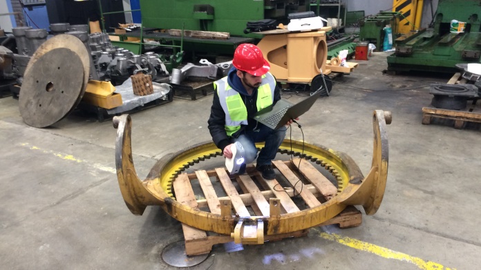
Ali had to scan on the premises of the manufacturing facility, wearing special safety equipment. He used the Artec Eva scanner along with the Artec battery pack as there was no immediate access to the mains power supply.

Ali Can Boysan scans the drawbar & yoke assembly with Artec Eva.

“The freedom of movement with the Artec battery pack was a huge advantage, I walked around the parts freely,” says Ali.

The parts featured some shiny and metallic surfaces, so those areas needed to be sprayed before scanning.

“Artec Eva was the suitable scanner for this job as the parts were very big and the accuracy required was in the range of Artec Eva’s accuracy,” says Ali. “The scanning was pretty fast and easy considering that those were huge parts, around 3 meters.”

Scanning the circle assembly with Artec Eva.

Each part took 30-40 minutes to scan in detail (including the top and bottom areas).

“Those were very fast scan sessions,” says Ali. “No other scanner can measure such big parts this accurately and fast.”

Once he was done with the scanning, Ali transferred the data to his computer at the Teknodizayn office. Post-processing each part in Artec Studio 11 3D imaging software took around 4-5 hours. There were numerous scans from different angles on both top and bottom sides of the parts, which added up to a large amount of data.

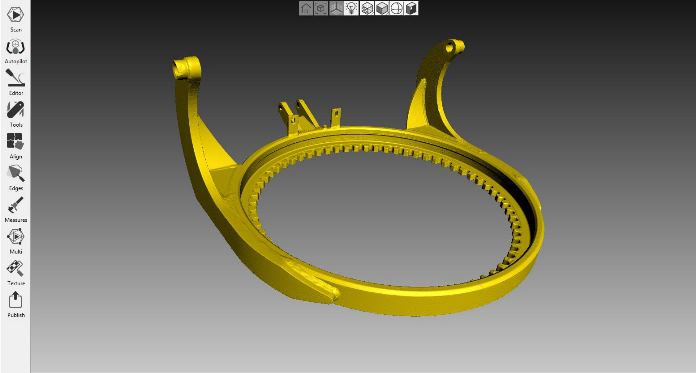
The .stl model of the drawbar & yoke assembly in Artec Studio 11.

The data was processed manually. First the unnecessary parts of the scans were erased, and then the scans were aligned using the quick and simple point to point alignment algorithm. Then Global Registration with Texture and Geometry was applied, which resulted in a dense and accurate point cloud that needed to be meshed. The next step was Sharp Fusion with the best possible resolution, creating .stl mesh models ready for reverse engineering.

The .stl model of the circle assembly in Artec Studio 11.

The files were exported to Geomagic Design X reverse engineering software. “This is no doubt the best, fastest and easiest program among its competitors,” says Ali. “Our reverse engineering specialist first auto-regioned the parts and then aligned them to coordinate planes. Later he parametrically drew the solid models accurately, feature by feature. After 7-8 hours of working on each part, the solid models were ready to be manufactured directly.”

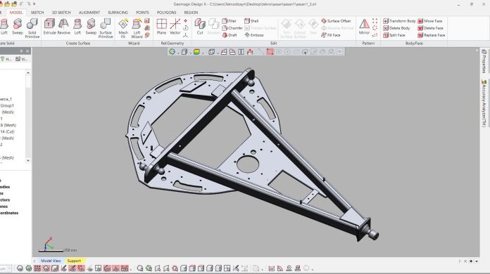
The drawbar & yoke assembly in Geomagic Design X.

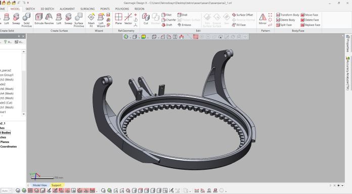
The circle assembly in Geomagic Design X.

The manufactured parts achieved the exact precision required. They were installed and tested on a working construction machine, proving to fit very well. Assan ASP were impressed with the results and bought an Artec Eva, Space Spider and Geomagic for SOLIDWORKS CAD bundle to improve their traditional workflow and use the technology in future R&D.

Want this delivered to your inbox?

Be the first to hear about new offers and updates from Artec 3D.Email *Sign me up to the Artec 3D newsletterArtec 3D may send me offers and promotions

3D SCANNER EXPANDS QUALITY ASSURANCE SERVICES

Product: HandySCAN 
Industry: Consumer Products and Retail

With its leading solutions in the fields of testing and measurement, technology systems, and networks and cybersecurity, Rohde & Schwarz, a technology company based in Munich, is one of the pioneers of a more secure and networked world. Founded more than 85 years ago, the group is a reliable partner for its customers in industrial and government sectors around the globe.

Planta de Teisnach Rohde & Schwarz

HandySCAN 3D for the Rohde & Schwarz Teisnach plant

The Teisnach plant is a system supplier and center for mechanical and electronic manufacturing within the Rohde & Schwarz network. Among the products manufactured at the plant are body scanners, housings, printed circuit boards, TV and radio transmitters, customer-specific wireless communications systems, micromechanical precision parts, and electromechanical custom products of all kinds. As a contract manufacturer, manufacturing services are offered as part of the complete range of services from product and software development to after-sales service.

As broadly diversified as the Teisnach plant is, so too are the measurement tasks, which can range from quality control workflows in the company’s own production lines to complete reverse engineering tasks for additive manufacturing projects.

Panel frontal que hay que medir en Rohde & Schwarz
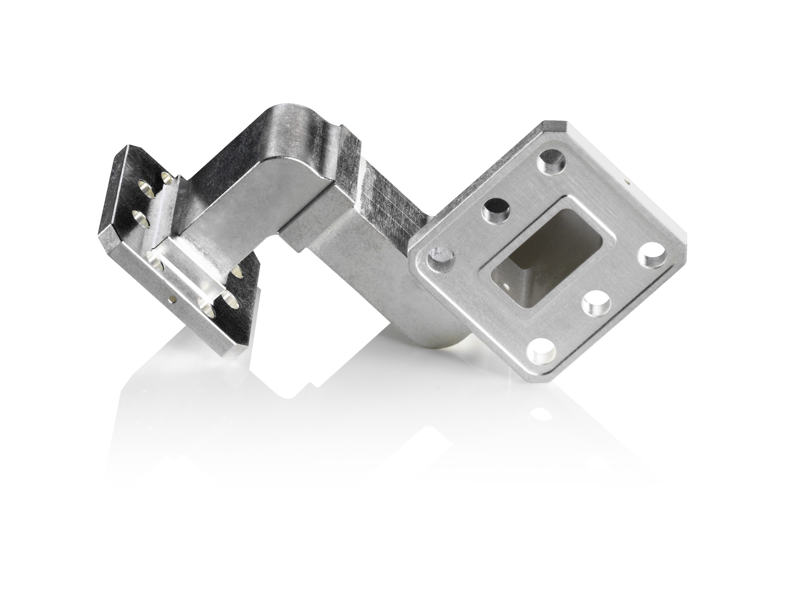
Guía de ondas que debe medirse en Rohde & Schwarz

A flexible 3D measurement system was to be introduced at the Teisnach plant in order to be able to supplement the range of services offered by the internal quality assurance department. The goal was to find a measuring tool that would offer the greatest possible flexibility in measurements as well as in terms of its applications: quality control, the measurement of vehicle interiors for modifications, inspections of free-form surfaces, and additive manufacturing processes. The aim was to achieve a high level of accuracy at all times. In addition, the team was looking to reduce inspection times as well as implement a faster and easier method to create 3D models.

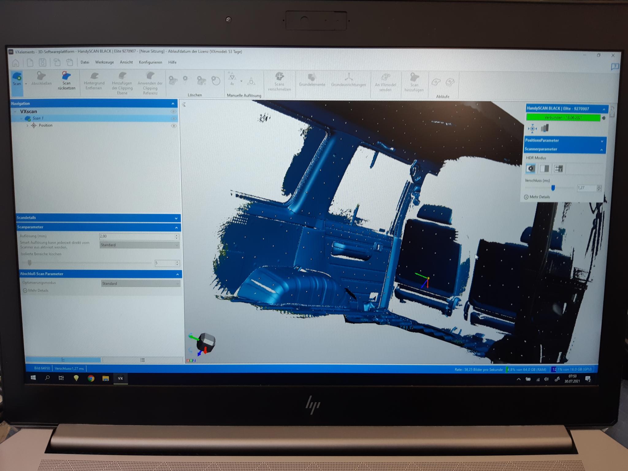
Accuracy requirements also included being able to objects ranging from the size of a 10x10x10 mm cube to the vehicle geometry of a jeep, with a required accuracy of up to 25µm.

Interior del crucero con objetivos preparados para escaneo 3D
Escaneo 3D del interior de un crucero

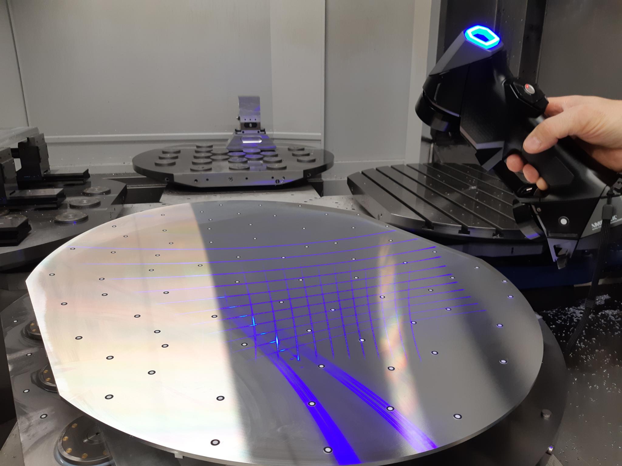
The HandySCAN BLACK | Elite from Creaform met all the requirements the measuring system and was integrated as an extension to the range of quality assurance services at Rohde & Schwarz, where other stationary tactile and optical measuring devices are already in use.

The decisive factor for selecting Creaform’s 3D scanning solution was the wide range of applications it could handle and following features:

  • High accuracy and fast acquisition of free-form surfaces and large components as well as quick assessment of the scan data. Thanks to non-contact scanning, highly sensitive surfaces and contours are never damaged—contrary to when a touch probe is used to inspect parts, such as gold-plated components.
  • Older or damaged stamping or injection molding tools for which no 3D data set is available can now be scanned. The generated scan data can be used to generate CAD model sand reproduce the tools.
  • Flexibility, precision and user-friendliness in handling the 3D scanner
  • Due to high scanning speeds, the amount of time needed for the design of vehicle interiors has been reduced from 1 working day to 2 working hours.
Escaneo 3D de un reflector con HandySCAN BLACK Elite (Imagen: Supracon AG)

summary

The HandySCAN 3D is regularly used in the Teisnach plant. Operators carry out 3D measurements in the dedicated measuring room, directly in the workshop for component inspections, and at customer sites.

“Due to the portability and high level of accuracy of the HandySCAN BLACK | Elite, we create added value for our customers that would not have been possible with our existing equipment. The Creaform system is extremely versatile and represents a great improvement for us, especially for the construction of special-purpose vehicles. For example, we can now accurately and quickly measure vehicle interiors for adaptive designs. In addition, we can efficiently check free-form surfaces with the scanner. The excellent service and support provided by Creaform should also be underscored. Overall, we are very satisfied,” said Josef König, Head of Quality Assurance/Testing Technology at the Rohde & Schwarz plant in Teisnach.

×