
3D scanning for traffic accident reconstruction: How Origin Forensics uses Artec Leo

Product: Artec Leo
Industry: Automotive and Transportation

Every time forensic accident reconstruction expert Jarrod Carter, Ph.D., steps up to a twisted wreck, he sees a book of stories waiting to be told: how fast was the car moving when it slammed into the bridge? How many seconds before impact did the driver hit the brakes? Was everyone inside wearing their seat belts? And how well did the car’s safety features protect its occupants?

When Carter and his team at Origin Forensics are called upon to help tell the story behind a wreck, they collect a wide variety of data, including 3D site models from drone photos and tripod-based laser scanners, police reports, scene photos or videos from police or others, surveillance footage, stop-light camera video, dash cam video, and event data recorder (EDR, a.k.a. the car’s “black box”) data.

These varied sources offer up a broad spectrum of details from the seconds leading up to and including the crash: brake usage, accelerator application, steering wheel angle, lateral/longitudinal acceleration, roll rate, engine RPMs, gear positions, and more.

A recent addition to their storytelling toolbox is the Artec Leo.

Origin uses the Leo, a wireless handheld 3D scanner unlike any other, to tell the story behind the twisted metal that is a wrecked vehicle. Based on experience, they have found that the Leo can faithfully generate a digital twin of a vehicle’s exterior or interior in under an hour, from bumper to bumper, with submillimeter accuracy.

Artec Studio software screenshot showing the Leo scan of the 2014 Dodge Charger

In the past, as part of their push to create digital twins of wrecked vehicles, they used a tripod‑mounted 3D laser scanner. The scanning process entailed physically repositioning the scanner numerous times around the vehicle, at multiple elevations, inside and out, to record as much detail as possible.

And, even with all the repositioning, the detail, while tremendously better than the plumb bob and tape measure method Carter used at the beginning of his career, was still lacking in the qualities necessary to create a convincing digital twin.

Another significant problem with the tripod-based laser scanner workflow was time. Each scan with a tripod-based scanner takes several minutes, not including the time associated with repositioning. A detailed scan of a vehicle could easily take an hour and, in some cases, as much as two or three hours.

A brief window of time to scan the entire vehicle

When Carter and his team get down to work, they generally have a window of four to eight hours of access to a vehicle, and scanning is not their only agenda item. And, as a rule, they treat their time with the vehicle as though it is the last time they, or anyone, will ever see it. So, any time savings afforded during the scanning phase provides extra breathing room to ensure that the inspection is as complete as possible.

“This (the issue of time) is one of the main reasons I kept my eye out for a better solution than our tripod‑based laser scanner. I was looking for speed and flexibility, which Leo gives us, especially since it has no cables or attached computer to slow you down. I no longer feel as though the rest of the inspection is being rushed so that I can make sufficient time to scan the vehicle,” Carter said.

Jarrod Carter Ph.D., scanning a Dodge Minivan with Artec Leo (at Insurance Auto Auction in Puyallup, WA)

“Because the vehicle is at the very center of our work, it is important to spend enough time gathering the data needed for its digital twin, even when that took us a lot longer than it does today. Now, with Leo, we collect the data for the vehicle’s digital twin so much faster. And I can use the touchscreen on the back to check the quality of the 3D mesh it’s making, the texture being captured, to make sure I have what I need before I leave,” said Carter.

“If I missed some aspect of the vehicle or didn’t get the detail I wanted in an area, I can easily rescan the bit I’m interested in with a wave of the scanner. It’s not like in the past with our tripod-based laser scanning workflow, where we’d have to wait till we got back to the office and started processing the data before we realized that some texture or geometry was captured less than ideally. With Leo, when we walk away from the vehicle, we’re confident it’s all there.”

The crucial need for extensive, true-to-life textures

As it relates to the texture data, Carter expressed high praise for the Leo’s capability, “What we weren’t expecting with Leo was the fidelity of the texture information it captures. The color and surface details appear photorealistic, or very nearly so. And the texture is not isolated to the individual points in the point cloud, like with a tripod-based scanner.”

“Instead, the texture fills the spaces between those points. A side benefit of filling in the gaps comes when you examine the vehicle from perspectives you didn’t consider when you were at the inspection. Now I’m not limited by the photos I took at the inspection. I can generate, on demand, what look like inspection photos of different aspects of the vehicle.”

Carter continued, “With Leo, we get highly accurate scans that provide more than enough geometry data for any analysis we need to conduct. And then you add in the photo texture to make it real. I remember the first time I zoomed in on the model of a vehicle we captured with our Leo. It was phenomenal. It looked exactly like the vehicle, which is what you want with a digital twin. We weren’t able to generate such high-fidelity models in the past. Not even close.”

Artec Studio screenshot showing the Leo scan of the Dodge Minivan

Having a digital twin of the vehicle that’s lifelike down to the smallest detail has become an expectation for Carter and his team since they started using their Leo. “When we sit down to go through the Leo scans in Artec Studio, it’s like being right there alongside the vehicle exactly as it looked during the inspection. We can visualize the evidence from any perspective we want, and we can measure it with exceptional accuracy,” Carter said.

Inspecting vehicle damage in Artec Studio

Carter explained one way they use the data from their Leo, “Once we compile the scans of a damaged vehicle, we align any undamaged portions of that vehicle with a 3D model or scan dataset of a similar undamaged vehicle. The comparison of damaged to undamaged allows us to determine the extent of crush on the damaged vehicle, which then provides a springboard for determining the direction and magnitude of collision forces, as well as how much energy was absorbed in the collision.”

“We can estimate change-in-velocity (delta-V) from absorbed energy and impact speed with enough other evidence. Additionally, we can use the comparison between the damaged and undamaged vehicles alongside our collision analysis to assist other experts who are trying to determine how the occupants were injured, and still other experts who are assessing the potential that some aspect of the vehicle’s design or manufacturing caused or enhanced those injuries.”

From 3D scan to biomechanical injury analysis

Origin Forensics also uses the data from Leo for biomechanical injury analysis. Here Carter and his team translate the outer crash event to the events involving the occupants inside the vehicle. A key aspect of the analysis focuses on determining how the occupants were interacting with the interior features of the car from the moment of impact onwards.

In Carter’s words, “We match up the occupant’s injuries to the elements of the passenger compartment that caused them, and determine whether any of the safety features there failed to perform as expected, whether that’s airbags, seat belts, or something else that was designed to mitigate injury. Could something have been designed or manufactured differently to prevent those injuries? We analyze every possible scenario, from beginning to end.”

Carter and Rothwell reviewing Leo scan data of the 2014 Dodge Charger in Artec Studio

During initial consultations with a client, in-person or over the web, Carter can share his screen and bring up the digital twin his team generated with their Leo, pointing out and explaining any relevant details.

Inspecting the Charger’s crush deformation patterns using Artec Studio’s surface distance mapping feature

As Carter explained, “Navigating around such a detailed 3D model provides a valuable adjunct to any 2D photos of the vehicle, which are frozen in time from the chosen perspective. Often the client will be curious about a specific aspect of the vehicle and we can take them right there and show it to them as though we were standing next to the vehicle or looking at a photo taken from that particular perspective.”

Using Leo scans for comprehensive vehicle damage reports

Following initial consultations with a client, there may be a need to submit a written report or to testify in deposition or trial. Generating exhibits that help the report reader or jury member understand the nature and extent of the damage sustained by an involved vehicle, or vehicles, is frequently an integral part of the process. And the 3D models generated from Leo scans provide the assets needed to create compelling visual exhibits.

Forensic Technician Kyle Rothwell, Origin Forensics’ in-house expert on Leo, described how he processes the Leo scans in Artec Studio software: “After importing our Leo scans, first I run Global Registration on a group of scans, then Outlier Removal on each of the groups, after which I align them.”

Rothwell processing the Leo scans of the 2014 Dodge Charger

“Then I clean up any stray geometry data, such as bits of glass, dirt, asphalt, etc. Once the raw data is registered, aligned, and cleaned up, I orient the scans to set the ground plane and rotate the object so that the right side view = the right side of the vehicle.”

Rothwell continued, “Then I run a Sharp Fusion, followed by a Fast Mesh Simplification. For a vehicle, a mesh density of about 2 million to 5 million triangles is appropriate for what we need. From there, I will apply the texture information for export and select the reduced glare. I normally use an 8K texture map to retain the smaller details. Then the model is ready for export, usually in .OBJ format with .PNG texture.”

3D digital twins of vehicles: even better than the real thing

Even though the majority of the cases that Carter and his team handle are settled out of court, or dismissed, and therefore never go to trial, if they do, their Leo has given them the ability to do what they always dreamed of: to put a true-to-life, virtual representation of the vehicle right in front of the jury.

“It’s even better than being up close with the vehicle itself, since with the digital twin, I can zoom in, rotate it however I want, and show everyone any part of the damage from any angle or magnification they’d like. And all of this evidence is fresh from the accident, so it represents what I saw during my inspection,” said Carter.

Preparing for inspection in Artec Studio: merging the Charger scan with an exemplar 3D model of the same vehicle

“In the not-too-distant future,” Carter hinted, “it may be commonplace that juries will have their own monitor or be wearing VR goggles when such exhibits are presented, which would make the impact of the Leo scan data all the more unforgettable. We could take them on a guided tour around or inside a vehicle, calling their attention to key aspects on demand.”

“In the past, we would have to bring the actual car to the courthouse and take the jury out to see it, which is an expensive operation with no guarantee the court will even allow it. With the data we generate from our Leo, now we can bring the car to the courtroom and let the jurors walk around it virtually.”

Using Artec Studio’s surface distance mapping to visually inspect the crashed Charger’s damage

So, what led Carter to the Artec Leo? While searching online and comparing all the handheld 3D scanners available on the market, Carter found the YouTube channel of Artec Ambassador Digitize Designs. From there, he reached out and spoke with Bo Helmrich, the company’s 3D Scanning Expert, who introduced him to the Artec Leo by sending videos of the scanning process and example data from a vehicle scan.

To show them how effectively the Leo would meet their needs, for the demo, Helmrich scanned the entire exterior of his Toyota Highlander with Leo, which took 32 minutes from start to finish. 90 minutes later and the scans were processed and ready to go. Carter remembered his first impressions of the 3D model he received:

“I was just blown away by the geometric detail, as well as the textures I was looking at because they’re massively important in the work we do. Now, without the quality of the underlying 3D data being so high, the textures wouldn’t be nearly as effective. Because both the textures and the 3D data contextualize each other.”

Carter explained further, “If for any reason the polygonal mesh is out of whack, distorted, or warped, even in the least, no amount of amazing texture is going to save that. Fortunately, Leo delivers brilliant results in both categories. We saw it then and we see it in every single project we use it for today.”

Learning to use the Leo, from unboxing to scanning in minutes

After purchasing their Leo, Carter and his team were given remote training on how to use the scanner and Artec Studio software. Rothwell commented on his experience with this:

“Learning how to use our Leo on smaller objects like a Pelican case was a joy. Right out of the box, Leo was ready to go and generating detailed models in just a few minutes. Scanning larger objects was a bit more challenging at first, so I found a different approach.”

He elaborated, “I learned that it worked best when I broke down the project into smaller chunks, which meant scanning each vehicle in sections and then loading them one by one in Artec Studio. Now we have consistent and accurate results every time.”

When asked about the difference in their work that Leo has made, Rothwell said, “When I think back to how we were scanning before our Leo came onboard, there really is no comparison.”

Forensic Technician Kyle Rothwell scanning a vehicle with Artec Leo

He continued, “The Leo is on an entirely different level. Operationally, it’s the feedback you get while scanning (real-time review), the ability to capture fine details, and the quality of color texture information that absolutely set the Leo apart.”

With their extensive engineering backgrounds and reconstruction experience, Carter and his team are regularly called to work on accidents that require a deep level of understanding of the physics involved in a crash. Further, they frequently extend their analysis to evaluating the injuries sustained by a vehicle’s occupants.

That’s the reason why big names such as Chrysler, Ford Motors, Honda, Jeep, Nissan, Progressive, Safeco, Toyota, and other companies and agencies across the United States regularly turn to Origin Forensics. Their in-depth investigations, detailed reports, and honest consultations bring existing clients back, and drive frequent referrals to new clients.

Origin Forensics’ guiding motto is “Veritas, Fidelitas, Claritas” (Truth, Faithfulness, Clarity). Their motto defines their mission, which is to discover the truth, while faithfully representing the evidence using the latest and best technologies, and then presenting their findings to clients, judges, and juries with the utmost clarity.

Carter explained why Leo is essential to their mission, “I want to push the boundaries of what’s possible in forensic accident reconstruction, and that requires me to always be on the lookout for the best technologies, so we can provide exceptional services and solutions for our clients. That’s why I chose the Artec Leo. It gives us that edge beyond anything else on the market.”
Modal Survey Testing for an unscathed journey to space

Product: Simcenter
Industry: Aerospace & Defense

All structures have natural frequencies, and it is often the most important feature of the structure, especially when it comes to dynamic response. Very often the vibrations must be investigated to quantify the structural response in some way, so that its implication on factors such as performance and fatigue can be evaluated.

Modal testing is a very useful and widely used technique to verify and investigate this behavior. It looks at the natural frequencies, mode shapes and damping of a structure and helps engineers understand how a design will respond to different dynamic loads.

In the space industry, this technique is also referred to as modal survey testing and is intended to calibrate and increase the accuracy of finite element (FE) structural dynamics model of spacecraft and space launchers. The validated models are important, among other things, for the prediction of the launcher vibrational characteristics, the aeroelastic stability and the dynamic environments to which payloads and on-board equipment are submitted to during the launch.

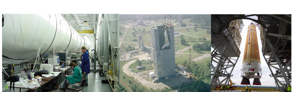
Courtesy NASA: Modal survey testing on Ares launch vehicle (left), Space Shuttle Challenger (middle) and SLS core stage (right)

A modal survey test consists of injecting forces, using electrodynamic shakers or in some cases also a modal impact hammer at a number of carefully chosen inputs. In the case of shaker excitation, burst random excitation is usually used because it is fast and efficient. When higher excitation levels are required, or for the assessment of nonlinear characteristics, stepped sine techniques are used. The forces are measured during the test, along with the response accelerations at many locations throughout the structure. During this test, the spacecraft is mounted in well-known boundary conditions, clamped or free-free, or a combination thereof. During the excitation, FRFs are measured.

After the test, modal curve-fitting technology is applied to extract modal information: resonance frequencies, damping values and mode shapes. The test results are used for the purpose of validating the entire FE model and correlating frequencies, mode shapes and damping assumptions. The significant mode shapes and frequencies are those that are primary contributors to launcher/spacecraft interface loads and internal loads.

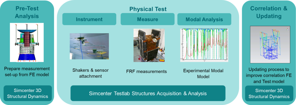
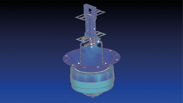
This process is illustrated schematically below. It shows how early FE models of the spacecraft can be used in Simcenter 3D Structural Dynamics to perform pre-test analysis and optimally design the test campaign. Simcenter Testlab and Simcenter SCADAS are then used to efficiently and reliably measure FRFs and accurately determine the best experimental modal model. Finally, the experimental results are further exploited to correlate the preliminary model with experimental results and to update the FE model to better reflect reality.

Different stages of the modal survey process: from test preparation, to the test execution, analysis and reporting.

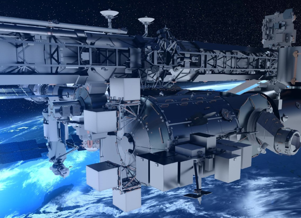
A good example of a program where a modal survey test was conducted is the Bartolomeo project from Airbus Defense & Space, carried out by Deutsches Zentrum für Luft- und Raumfahrt (DLR). Simcenter SCADAS Mobile hardware has been used as the critical measurement equipment for the modal survey test that was meant to update the FE simulation model of the Bartolomeo platform. This enabled the team to simulate and predict aspects that could only be done using simulation and analysis, such as how the platform would couple with the launcher.

Winery Tops Off Tour with 3D Printed Map of Vineyard

Product: CJP
Industry: Academic

Wine aficionados already know: the environment in which wine grapes grow impacts the final characteristics of the wine. Some subtly, some not so subtly. This element is known as terroir, a term that describes the complete natural environment from which a wine comes, including the climate and topography all the way down to the soil. These variables are anything but inconsequential to the flavor, color and body of the wine, and can be fascinating to learn about. Yet short of walking through a vineyard with surveying poles and kneeling to rub earth between your fingers, it can be challenging to get a comprehensive picture of terroir to fully appreciate the nuances at play in your glass.

This was a problem for Ten Minutes by Tractor, a winery on the Mornington Peninsula, Australia, that wanted to give its patrons a deeper understanding of its wines. Ten Minutes by Tractor is made up of three vineyards located ten minutes apart with widely different environmental characteristics that deliver vastly distinctive wines. The winery’s goal is to add value to its wine tour experience wherever possible by sharing its knowledge of wine making with its visitors. Yet verbally explaining the impact and differences in terroir proved minimally engaging without a visual reference. The winery needed a way to clearly communicate the contributions of the region to its wines that was accessible and effective.

vW Maps, a trusted publisher of Australian wine regions, offered a solution and worked with the vineyard to create a digital 3D appearance model of the terrain. Using a scaled representation, the winery could show visitors the spatial relationship of the vineyards to one another as well as the interplay of environmental features that were responsible for creating distinctive character among the wines. vW Maps further transformed the 3D data into a 3D printed appearance model at 1:160,000 scale with a five-fold elevation exaggeration. The final 3D printed models could then be examined and discussed as a memorable

vW Maps merged graphic and cartographic design to create the data for the 3D printed map.

Designing a 3D map of vineyard terrain

vW Maps took great care to merge and adapt graphic and cartographic design elements to get an effective mix of terrain selection, generalization and simplification with the right typography, color and balance. The resulting representation focuses viewer attention on the vineyards, terrain and most important landmarks. This allows cellar door staff at Ten Minutes by Tractor to easily reference and explain the complicated factors of terroir over a scaled appearance model of the terrain that is distinctive, appealing and easy to read. The map also helps cement the cellar door experience in visitors’ minds as a unique learning aid and conversation piece that stands out from other wineries in the region.

According to vW Maps Owner Martin von Wyss, although the appearance model design was digital in origin, “The terrain model is tangible and accessible when placed on the tasting bench next to a glass of wine, and it makes the geography of wine fun, engaging and easy to understand.”

Through an examination of the “Terroir Explainer,” as von Wyss calls the model, winery customers gain an understanding of the vineyards’ physical conditions, such as elevation, slope, aspect, and drainage. The cellar door staff supplements the 3D printed model with additional information about soil and climatic conditions to complete the picture of what shapes the wine. Von Wyss says the 3D printed appearance model effectively highlights the many variables at play in viticulture to sharpen environmental awareness, heighten respect for the vineyards and deepen clients’ appreciation of the nuances of wine.

The 3D printed model was created at 1:160,000 scale with a five-fold elevation exaggeration.

3D printing terrain maps in full color

Once vW Maps had prepared the 3D terrain data, it sent separate files for the topography and map to 3D Systems On Demand Manufacturing services. Once received, 3D Systems’ manufacturing experts scaled and wrapped the design data onto the 3D file for printing in full color using a ProJet® CJP 660Pro. This printer uses 3D Systems’ ColorJet Printing (CJP) technology, a powder printing process popular for detailed, multicolor parts in architecture, consumer goods, the arts and other applications where color and appearance are of primary value. Offering photorealistic color in a full CMYK spectrum, the build envelop of the ProJet 660Pro is capable of producing large prints in a single piece. vW Maps and Ten Minutes by Tractor took advantage of this large print size, with final model dimensions of 252mm x 379mm x 18mm.

3D Systems’ On Demand Manufacturing experts prepared, printed and finished the model within the week and promptly sent it back to vW Maps for final delivery. Next to the wine, the 3D printed appearance model is the centerpiece of the cellar door experience at Ten Minutes by Tractor. According to the winery’s general manager Chris Hamilton, it also helps Ten Minutes by Tractor stand out and garner word-of-mouth interest. “There’s no doubt that our terrain map is a key component that makes a visit to our cellar door distinctive from visits to our nearby competitors,” says Hamilton.

The terrain appearance model was a finalist in the 2016 Victorian Design Awards, which recognizes and awards Victorian designers and businesses that demonstrate excellence in their use of design.

The terrain appearance model was a finalist in the 2016 Victorian Design Awards

Artec Space Spider meets Car SOS to restore one of Britain’s best-selling auto classics

Product: Artec 3D Space Spider
Industry: Automotive and Transportation

Car SOS TV hosts (left and in the center) and the lucky owner of the restored Ford Cortina Mark III after the grand reveal

Meet Bobby

When 54-year-old Sikh historian and writer Bobby Singh bought his Ford Cortina Mark III XL back in 1999, he didn’t think it would take long for him and his 1970s British classic car to hit the road again.

But his plans came to a screeching halt in 2002 when Bobby, then in his mid-thirties, suffered a stroke. Not long after, in 2008, his family business collapsed, and then Bobby was diagnosed with heart disease. Throughout this devastating chain of events, Bobby’s family lost everything. Then, in 2018, yet more bad news arrived: doctors discovered a benign tumor in Bobby’s brain.

For more than 20 years, his Mark III sat locked away in the garage at his family’s home in Syston, a town in East Midlands, England. The once-remarkable car had suffered visibly in the process, having become overgrown with corrosion, rot, and dust.

Calling in Car SOS

Until one day, his wife Harvinder and their son Aman decided to resurrect Bobby’s old automotive dream. And what do people in the United Kingdom do when they need to rescue their friend’s or family member’s classic from rusty retirement? That’s right: they call in Car SOS, a British automotive TV show aired on National Geographic automotive TV show that documents done-in-secret classic car restorations for needy or down-on-their-luck owners. The show is driven by two hosts, car enthusiast Tim Shaw and master mechanic Fuzz Townshend, who together with their team of automotive technicians bring old classics back to life.

Touched by the story that Harvinder and Aman shared, Tim and Fuzz jumped in to help right away. Soon enough, they arranged to meet Harvinder and Aman, and to pick up Bobby’s Mark III for major restoration, with the hope that the project would give Bobby a much-needed boost.

Car SOS hosts meet Bobby’s family and his car for the first time (Photo: National Geographic)

Although at first glance the car looked as if it was in fairly decent condition, the crew at the legendary Car SOS workshop in Birmingham conducted a thorough check-up followed by disassembly, which revealed that Bobby’s Ford Cortina needed a considerable pick-me-up of its own.

For instance, nearly the entire undercarriage had rusted over and was covered with rot, the 1600cc Kent Crossflow engine was fully worn out, requiring a new set of gaskets and servicing, and the back axles, known to be prone to wear, demanded a thorough inspection and refurbishing.

Some parts were also missing, including the center console, which Tim, responsible for sourcing all the parts in the show, was sent on a mission to find. Sourcing auto parts and components for classic cars has always been a challenge (not only for these technicians!), and this time, the host was out of luck when trying to hunt down the missing piece. He did, however, manage to borrow one for a few days, so that they could use it as a reference model to design the new console. But, given the show’s tight timeline, they needed a solution, and fast. That solution was, of course, 3D scanning and 3D printing.

3D scanning at Central Scanning, Ltd.

To construct an extremely-accurate 3D reproduction of Cortina’s console, Tim reached out to Central Scanning, an Artec Ambassador in the UK. Based in Birmingham, Central Scanning has been one of the key providers of 3D scanning products and services in the UK since 2006, covering a wide range of industries from aerospace to engineering, as well as medical and artistic applications. As 3D scanning experts, Central Scanning’s engineers have accomplished countless projects with the help of Artec 3D scanners, and this one would prove to be no exception.

“Quite a few of us at Central Scanning are car fans, and I have a few classic cars myself,” said Nick Godfrey, managing director of Central Scanning. For Nick and his team, the program has always been of interest – especially since the Car SOS team’s members are all based in Birmingham.

“It’s always been nice to think that one day, Central Scanning may appear on TV, and so when the discussions started, we were very keen to support this project however possible.”

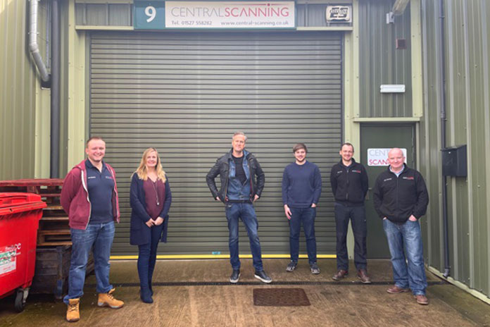
Tim Shaw from Car SOS and the Central Scanning team (Photo: Central Scanning)

Having scanned everything from entire cars to chassis, engine parts, interior parts and suspension components for classic cars in the past, the team was ready for the challenge. Tom White, Central Scanning’s applications engineer at the time, met Tim at their workshop soon after the Ford had safely and secretly been relocated to the Car SOS premises. After Tom examined the console, he concluded that Artec Space Spider would be the most suitable 3D scanner for the job.

Developed for use on the International Space Station, Artec Space Spider is known for its ability to capture complex shapes and fine details with a metrological accuracy of up to 0.05 mm and an ultra-high resolution of up to 0.1 mm. This is why many engineers, and car mechanics in particular, use the scanner for reverse engineering, as well as quality inspection of car parts.

While this console isn’t particularly big, it does feature a hard-to-scan glossy black finish: a type of surface notoriously difficult to 3D scan. To assist the process, the object was coated with matting spray pre-scan. In this case, Tom used AESUB Blue matting spray, which would vanish from the surface post-scan.

The goal was to create an accurate, true-to-life model for 3D printing. Within the hour, the part had been prepared for scanning, had all its data captured, and was processed first into a mesh and then a CAD model in Artec Studio with some additional modeling done in Autodesk Fusion 360. After being prepared in GrabCAD Print, the final STL file was sent for 3D printing; this took another 8 hours to build an exact copy of the matching console, layer by layer.

On why 3D scanning was chosen as the go-to method to reverse engineer the missing console, Nick said: “The scanning provided a quick solution to be able to gain accurate data without affecting the original part as Tim had ‘borrowed’ the part from another car!”

While an alternative could have been to take a mold from the part and make a fiberglass part, this option would have taken longer, and been far more expensive.

Creating an exact replica was necessary to get the car road ready (Photo: National Geographic)

Just like that, the missing part was recreated from bottom to top, accurate down below a millimeter, and soon Tim was on his way back to the workshop with a freshly 3D-printed console.

Let the restoration begin!

Yet it was still too soon for the new part to take its place in the Ford Cortina’s interior; this was just the beginning of what turned out to be a full-blown makeover. As Tim had been chasing down this rare part, Fuzz unearthed a whole array of mechanical issues while taking a closer look at the crossflow engine and its inner workings.

The engine was fully worn out and needed a complete overhaul, and the car body wasn’t looking too well either. After the Cortina came back from sandblasting (a process that involves removing paint or rust from the car’s body or frame), more trouble was revealed: the entire body of the vintage auto was covered in holes and patches from front to rear.

Restoring the car to its original smoothness with sandblasting (Photo: National Geographic)

The Car SOS bodywork team got straight to work, welding and grinding to get rid of those holes and make the body surface as smooth as it once was. Following this, the car body went straight into the paint booth for a spray coat of that oh-so-’70s tangerine paint. Then, it was time for all the mechanical work to commence: installing the new gasket set in the rear axle and refilling it with some fresh oil, repairing the clutch friction plates, and much more.

After that, all the new and restored inner and outer parts were reinstalled in the freshly painted body, including the previously 3D scanned and printed center console.

When all the pieces were fitted together, it was time for Tim and Fuzz to get the engine started and return the fully restored Ford Cortina Mark III to Bobby.

Improved Manufacturing Process with Artec 3D Scanner and Geomagic Control X Software

Product: Control X, Artec 3D Space Spider
Industry: Foundry

As new production technologies evolve, new technical challenges arise in manufacturing the best possible part. Often a contract manufacturer has to tune the new process significantly the first time it attempts production to understand elements such as shrinkage, surface finish, and repeatability. Additive manufacturing (AM) is no exception, and yet tools to track these elements for this production methodology have lagged behind. That is now changing.

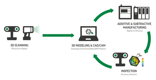
Most manufactured goods follow a common process through their life cycle to production. Design, manufacture, inspect is a generalized way to consider process, stages, and responsibilities, each one being key to producing high-quality parts. Depending on the complexity and nature of the part being manufactured, the real workflow can have many tuning loops and feedback.

Flujo de trabajo de fabricación

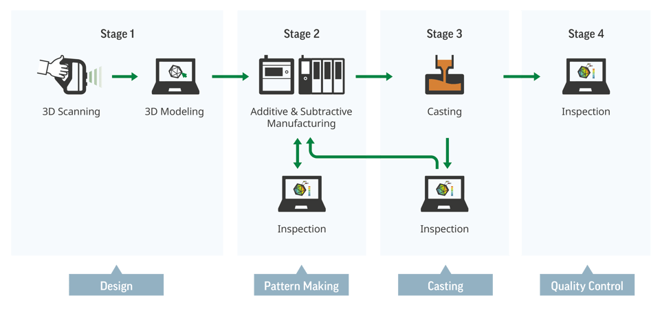
The following workflow example demonstrates how the Artec 3D Space Spider scanner and Geomagic Control X software together provided total shape capture and analysis on 3D-printed wax casting patterns and cast parts at all stages in the design, prove out, and manufacturing process.

Infografía de flujo de trabajo de diseño, creación de patrones, fundición y control de calidad para el software de inspección Geomagic Control X y el escáner Artec 3D Space Spider
Software de escaneo Artec Studio
Artec Studio scanning software

The Artec 3D Space Spider is an ultra-high-resolution handheld 3D scanner that excels at precisely capturing small objects and complex details for dimensional inspection.

With plug-and-play operation, the Space Spider scans objects easily, without complicated preparation and extensive user training, allowing customers to digitize parts anywhere. The Artec 3D proprietary target-free algorithms allow the scanner to track the object by its shape and color alone—no need to apply targets to the object.

Geomagic Control X from 3D Systems is an industrial metrology software that enables root cause analysis (RCA) and correction for manufacturing. As a 3D scan-native software, Geomagic Control X is an ideal solution for metrology with portable measurement devices. With Geomagic Control X, more people in your organization can measure faster, more often, and more completely—from anywhere.

The total solution provides unique insight into successful production in a complex manufacturing process. The result? Greatly-improved overall final part quality, accuracy, and repeatability.

Design

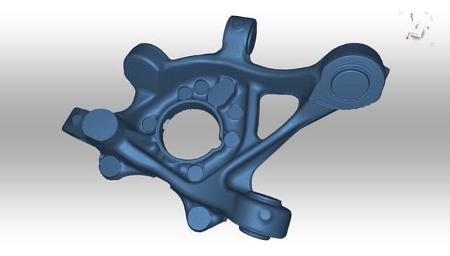
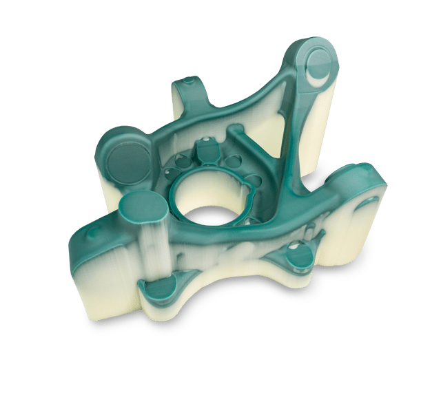
For this workflow example, we replicated a real customer project, but generalized the details. In this case, the customer was developing a specialized, autonomous-driving, light-duty vehicle. To speed time-to-market, they selected and combined a range of components and systems from vehicles on the market today to complete a working prototype. In this process, they found a specific steering knuckle (one each per) was valuable to the project and they needed to digitize and capture the design so that they could further modify and manufacture it in a light-weight material.

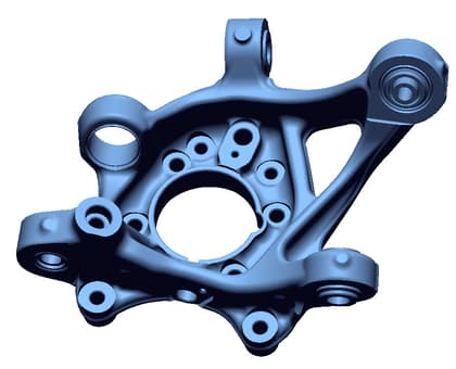
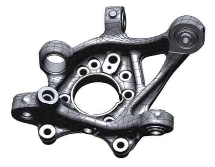
To begin work, they 3D scanned and reverse engineered the original casting. They used the Artec 3D Space Spider scanner for rapid digitization and then quickly and accurately modeled the part in Geomagic Design X with a unique hybrid-modeling approach. Typically, customers will follow either an as-built (very accurate) or design-intent (dimension-driven) modeling method. A hybrid modeling approach consists of combining both of those concepts to deliver a CAD solid model result that has both dimensioned features as well as highly-accurate NURBs surfaces. Using this strategy, they completed the model in under 1.5 hours and live-transfered to SOLIDWORKS as feature-based CAD.

Escaneo de piezas originales
Original part scan
Modelo CAD híbrido
Hybrid CAD model
Modelo derrotado para imprimir
Defeatured model for print
Impresión de cera sin terminar de la impresora 3D ProJet® MJP 2500 IC de 3D Systems
Unfinished wax print from the ProJet MJP 2500 IC
Sección transversal de muestra del modo de relleno disperso impreso en la impresora 3D ProJet® MJP 2500 IC de 3D Systems
Sample cross section of sparse infill mode printed on ProJet MJP 2500 IC

Pattern Making

AM has been used in aerospace and automotive applications to produce sacrificial casting patterns for decades. With recent advances in 3D printing, industrial-grade patterns can be printed in wax or polymer at a significantly lower cost, which work seamlessly in the investment-casting process. 3D Systems is seeing more distributed adoption of tool-less additive pattern making and will continue to grow as the technology becomes more accessible, rapid, and precise.

For any additive process that involves heat energy in material deposition or post processing, there is some amount of part warpage and settling that could occur. Parts that have significant mass or a significant cross-sectional area will retain heat for longer than smaller or thinner parts.

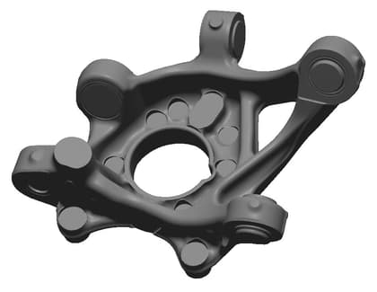
Based on this knowledge, 3D Systems tested two printing methods with the goal of having the lowest possible cost of printed goods and the highest level of dimensional stability: a completely solid wax-printing method as well as a thin, shell/sparse wax-infill method. Both were prepared with 3D Sprint build client software and printed on the ProJet MJP 2500 IC 3D printer that produces wax casting patterns. From prior experience, we found that a 2 mm shell with a 50% sparse infill ratio produces high-quality, stable parts when printing relatively large parts.

After post processing and cooling time, we used the same Artec 3D Space Spider scanner to scan the two patterns with relative ease. The unique shape of the parts, the green wax color, and the slight dulling and whitening effect of the post process enabled our scanning technician to capture the models smoothly using Geometry + Texture tracking.

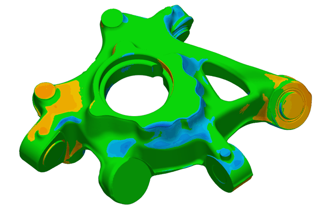
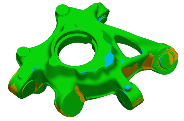
Using Geomagic Control X, we imported the 3D Sprint build file directly and inspected each part in its exact print orientation for the inspection routine. Knowing that we would be scanning the subject part iteratively to improve the process, we were able to set up one detailed inspection project and duplicate it several times while maintaining the entire process development history in a single Geomagic Control X file. After completing the scans, we simply dropped each new STL file into the Geomagic Control X project and the evaluation process automatically took over, resulting in high-quality, repeatable reports.

We found that, generally, all areas with machining offsets were within the casting tolerance, but the more free-form areas presented trends outside a tight tolerance band. We believe this properly correlated our assumptions that large cross-section areas retain heat and potentially change shape when cooling.

Our comprehensive analysis for this stage helped us draw some conclusions that 3D printing with the wax pattern was not only more cost-effective, but also more dimensionally-compliant after post processing.

  • Material usage was reduce by about 35%.
  • Material cost was reduced by about 27%.
  • Overall compliance with tolerances were increased by about 10% (using 3D comparison).
  • The solid part did not pass the tolerance threshold
  • The infill part passed the tolerance threshold.
  • Long-term dimensional stability at room temperature was improved over the solid part.
Análisis de patrones de cera sólida
Solid wax pattern analysis
Patrón de cera con análisis de relleno
Wax pattern with infill analysis

Hearing Aid Company Solves Manufacturing Challenges with Rigid and Rubber 3D Printing Production Resins on Figure 4 Solution

Product: Figure 4
Industry: Consumer Products

WS Audiology, a leading hearing aid company, has adopted 3D Systems’ Figure 4 high-speed 3D printing solution to improve the quality and function of its injection molding manufacturing processes with the 3D printing of production-grade grippers, fixtures, and prototypes at its Lynge, Denmark, site. A pioneer in 3D printing for the manufacturing of hearing aid shells, WS Audiology has expanded its use of 3D printing to solve a range of manufacturing line and product development challenges, citing the quality, performance, and material versatility of Figure 4 as key benefits of the solution.

“We saw early on that the Figure 4 had the right qualifications in terms of output quality, production performance, and [breadth] of materials.”

– Henry Frederiksen, Tool Designer, WS Audiology

IMPROVING QUALITY AND FUNCTION OF SMALL PARTS TRANSPORTATION

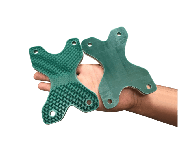
There are many different injection molded parts within WS Audiology’s Widex brand hearing aids. These parts include encasings, contacts, and blocks for electronics that are fitted in each hearing aid, some of which are as small as 8mm x 3mm. Due to their size, this category of parts requires robotic rather than manual handling, involving suction cups for larger parts, and metal grippers for small parts. However, these handling methods have shortcomings. The suction cups have difficulty properly orienting parts, which leads to loss of grip, and the metal-based grippers are prone to leaving marks on the parts in addition to having long manufacturing lead times.

Figura 4 parte impresa con regla para mostrar precisión

High Accuracy 3D Printing

WS Audiology experienced several major benefits of using 3D printing to manufacture hearing aid shells, including both a final product with substantially higher-quality and an eight-fold productivity increase. Following this success with the technology, the decision to extend the company’s 3D printing applications to solve its workflow transportation problems was an easy one.

3D Systems’ Figure 4 solution is a projection-based additive manufacturing technology that uses a non-contact membrane to combine accuracy and amazing detail fidelity with ultra-fast print speeds. WS Audiology uses the Figure 4 Standalone, an affordable and versatile solution that offers speed, quality, and accuracy with industrial-grade durability, service, and support, as well as quick material changeovers for enhanced application versatility.

Rapid Design Iteration

The task was assigned to WS Audiology’s Tooling Department. According to tool designer Henry Federiksen, taking on this project with Figure 4 gave him a lot of confidence, and the speed of the solution enabled more parts to be produced, tested, and confirmed in a shorter period of time.

 Production Speed

A key benefit to using the Figure 4 solution is the ability to produce parts without tooling. WS Audiology is able to go directly from a digital file to a physical part, removing a significant amount of time from its typical processes. According to Frederiksen, 3D printed grippers are usually available in a day or two, leaving a lot of happy customers in the injection molding department.

 Production-Capable Materials

For WS Audiology’s production tooling applications, it is taking advantage of Figure 4 PRO-BLK 10 and Figure 4 RUBBER-65A BLK. The range of materials available with the Figure 4 platform makes it possible to address a broad set of applications with greater diversity in material properties, with material chemistries that have been engineered for long-term use, up to 1.5 years for outdoor parts and up to 8 years for indoor parts (per ASTM testing methods). Figure 4 PRO-BLK 10 is a production-grade rigid material, and Figure 4 RUBBER-65A is a mid-tear strength, production-grade rubber with Shore 65A hardness and a high elongation at break.  

Placa de construcción de la impresora 3D independiente Figure 4 en WS Audiology llena de piezas

Automotive supplier designs and builds sophisticated mechatronic parts with Siemens solutions

Product: NX CAM
Industry: Automotive and Transportation

NX, Teamcenter and Tecnomatix enable Pollmann to maintain a leading position as an automotive components supplier

Almost every car manufactured around the globe includes components made by Pollmann International (Pollmann). The family business boasts more than 130 years of innovation experience and is among the global market leaders in its niche. At the company’s headquarters in Austria, Pollmann engineers create highly complex mechatronic assemblies.

Among these products are sunroof kinematics, door latches and assemblies for the engine compartment and for the power train. Recently, parts and assemblies for e-mobility applications have been added to the company’s portfolio of custom solutions. From five production facilities in Europe, Asia and North America, Pollmann supplies automotive brands around the globe with these intelligent combinations of metal, plastics and electronics.

Key technologies used in the production of these components are insert injection molding, where metal parts are overmolded, and outsert injection molding, where plastic functional elements are molded onto carrying metal structures. Pollmann acts as a one-stop-shop for Tier 1 suppliers. Customers benefit from components created as integrated solutions from a single source, complete with the stamping dies and injection molds and the automated systems required for part production. At all Pollmann sites, the parts are combined to form complex assemblies ready for direct integration with the customers’ production processes.

A heterogeneous software landscape

In the past, Pollmann engineers used parametric software for computer-aided design (CAD) from one supplier and several different brands of computer-aided manufacturing (CAM) software for numerical control (NC) programming. There was no product data management (PDM) or product lifecycle management (PLM) system.

All product-related information was stored in various file-based systems. This variety of software tools and information silos became increasingly cumbersome. Due to the file-based storage, release management caused extra work and time-consuming searches as well as frequent errors. The absence of a common information base also caused delays in cross-location engineering projects. Moreover, using inconsistent methods for processing neutral format CAD data made processing 3D models from external sources difficult.

Pollmann management was aware that they needed to improve engineering information management in order to stay competitive. “Our aim was to reduce unproductive work and manage changes required by customers quickly and with tracability,” says Markus Stocklasser, design engineering manager, Pollmann. “To make global collaboration easier, we developed a vision to store and manage all product-related data and documents in a PDM system.”

An integrated solution with Teamcenter and NX

During initial market inquiries, Pollmann’s experts extended the scope of their product search to include workflow functionalities, changing their specified target system from PDM to PLM. Pollmann’s experts evaluated five software suppliers. Among these were independent PLM software providers as well as companies offering both PLM and CAD/CAM and computer-aided engineering (CAE) software. “We had also discovered shortcomings of the strictly parametric design software we had been using,” says Markus Hiess, PLM/ CAD administrator, Pollmann. “To overcome these and to achieve greater data consistency, we decided to pursue a more integrated approach, combining a new PLM system with more flexible software for CAD and CAM.”

Out of the three remaining contestants, Pollmann’s engineering experts chose a combined implementation of Siemens Digital Industries Software’s Teamcenter® software, an adaptable PLM system that connects people and processes across functional silos with a digital thread, and Siemens’ NX™ software, an integrated CAD/CAM/CAE solution.

Spanning all aspects of product creation, NX ensures full data consistency and associativity all the way from part design to tool assembly without external interfaces. NX tool design applications can work with almost any type of 3D input data. Engineers can verify their designs without leaving NX.

Future-oriented software strategy

“Using this comprehensive solution, product and part designers, tool designers and NC programmers can share the same software environment,” says Stocklasser. “As tool development can commence even before product design is completed, this considerably speeds up the overall process.”

“Teamcenter gives us full control of our product data,” adds Hiess. “The software also allows us to enforce our processes across departments and locations while relieving colleagues of undesired side activities.”

The superior properties of these software products were not the only reasons for Pollmann’s decision. “Siemens’ software strategy was a similarly important factor in our decision-making,” says Stocklasser. “The long-term commitment to extend its portfolio to cover all aspects of product and production with a digital twin and with full data consistence spoke strongly in favor of that global player.”

In a first implementation phase, Pollmann equipped about 60 workplaces across all design and tooling departments generating CAD and CAM data as well as the tooling department at its Austrian headquarters with Teamcenter and NX. To ensure a smooth transition, five key users and an administrator were designated for system implementation. As most Pollmann parts are individual items, they did not migrate any product data but decided to recreate parts in case of repeats.

Design automation as a benefit

This transition showed considerable beneficial effects. “Using NX, motion simulations and filling studies for plastics as well as FEM calculations help us verify and evaluate part geometries even before the prototype phase,” says Hiess. “Using Teamcenter as the single source of truth, our various departments jointly develop cost-optimized solutions and innovations.”

“While NX does support parametric work, the unparalleled flexibility of its synchronous technology reduced the time required for mold design by 35 percent,” says Stocklasser. “I was also pleasantly surprised by the software’s sheet metal capabilities, especially the speed of flat projection of complex freeform sheet metal parts.”

In their tool designs, Pollmann’s engineers had always implemented logic functionality. They now utilize NX Open to automate complex and repetitive tasks. They are also using NX Mold Wizard, the NX Progressive Die Wizard and NX Electrode Wizard. Without any programming, this powerful set of automated applications can greatly optimize tooling design. NX Mold Wizard provides automated sequences for working with part geometry, creating parting surfaces and enabling automatic updates. The NX Progressive Die Wizard guides users through all of the stages required to construct a progressive die, streamlining complex processes and automating tedious tasks for significant time savings.

The NX Electrode Wizard allows automated electric discharge machining (EDM) electrode design using the die’s model that in turn has been derived from the 3D model of the part. Electrode design was once a week’s worth of work for highly skilled specialists” says Hiess. Using the NX Electrode Wizard, our people can now complete this task in two days.

“Taking advantage of the considerable speed gains NX brings, we can now design our tools with a much greater wealth of detail,” says Stocklasser. “This directly results in improved quality and manufacturability, eliminating all manual rework.”

GROB automates manufacturing of CNC machines for the automotive industry

Product: NX CAM
Industry: Automotive and Transportation

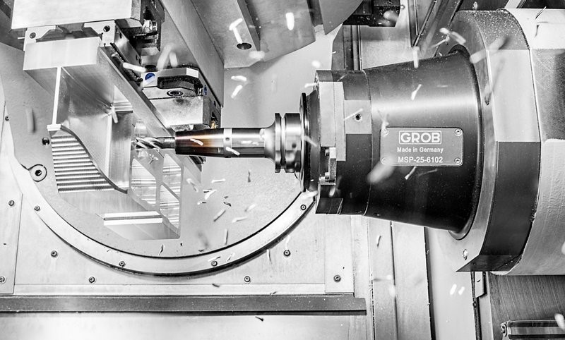
GROB-WERKE GmbH & Co. KG (GROB) is a family-owned company and leading manufacturer of production plants and CNC machines for the automotive industry, ranging from universal machining centers to fully automated production and assembly systems.

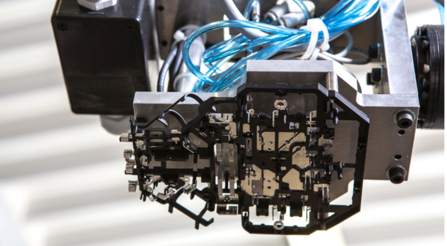
GROB producción de piezas reales con mecanizado CNC automotriz

GROB faces several business challenges, including:

  • Designing leading-edge automotive production equipment
  • Using standardization to manage high customization level
  • Relying on global engineering collaboration
  • Maintaining their leadership position in competitive industry

GROB owes a large part of its success thanks to the ability to anticipate and quickly respond to changing market trends using a high level of automation. With Siemens’ Xcelerator software portfolio, GROB’s engineers can design, engineer, and manufacture production equipment and CNC machines for the automotive industry.

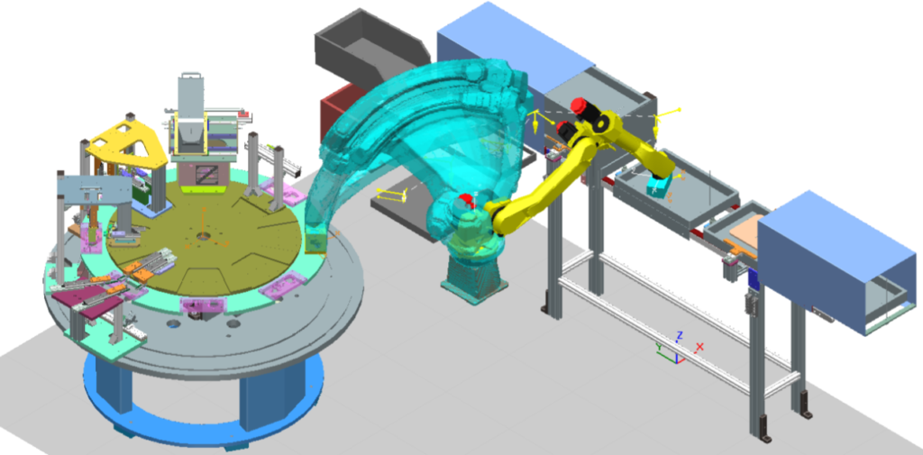
Los ingenieros de GROB utilizan Plant Simulation, NX CAD, NX CAM y Teamcenter para la planificación, el diseño, la validación y la programación CNC de proyectos.

Automate CNC machines in the automotive industry with NX CAM

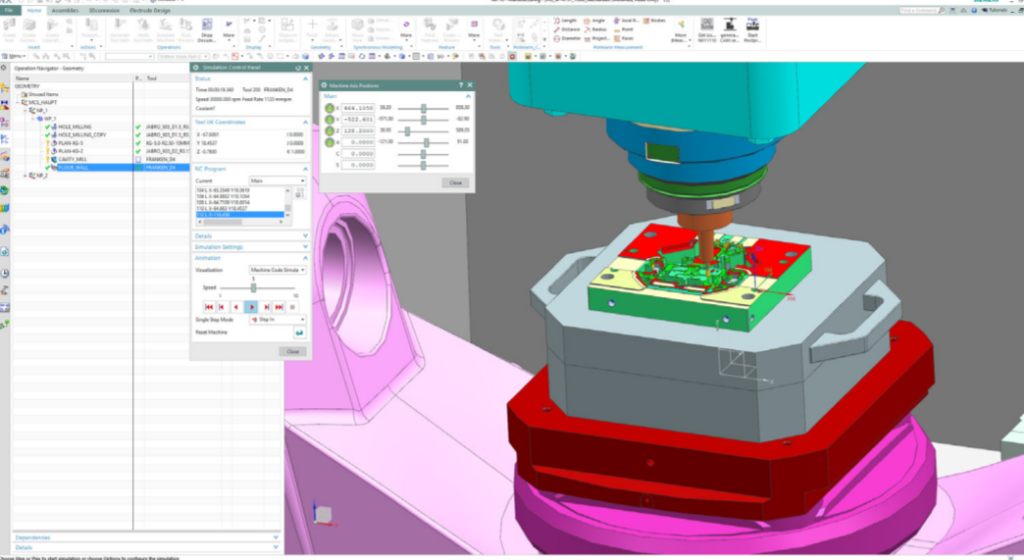
GROB engineers create a digital twin of each production machine and line using NX. They also use NX CAM to automatically create CNC programs using Feature-Based Machining. This capability helps GROB’s programmers to create a machining rule library containing standard bore types, pockets and surface definitions, including the tools required for machining operations. Before sending the CNC programs to the machine tools, the engineers simulate complete machining processes using the NX CAM’s machining simulation capabilities, ensuring error-free production on the shop floor.

To better collaborate, the engineers exchange 3D models between production facilities, using Teamcenter as the central information hub. These models are then CNC programed locally, making it easier for the engineers at each facility to adjust the CNC programs according to the available resources and equipment.

Using NX CAM for fea­ture-based machining helped us automate design and CNC programming work. Recognizing 95 percent of GROB standard bore types and 70 to 80 percent of other fea­tures, the automatic feature recognition has reduced CNC programming time by 30 percent and considerably reduced the number of different tools used.

Christian Lisiecki Director and Head of Machining Systems GROB 

Using Femap to make parts suitable for deep-space missions

Product: FEMAP, Simcenter
Industry: Aeroespacial

Siemens Digital Industries Software solution helps Almatech optimize unprecedented high-performance, lightweight component designs

Using Femap makes it easy to reiterate the simulation process.

Dr.Luc Blecha,CTO Almatech

Top precision and maintenance free reliability

To boldly go where no human has gone before was the mission of the starship Enterprise. Its aim was to explore strange new worlds, to seek out new life and new civilizations. While manned space voyages of this magnitude remain fictitious, mankind is sending out space probes to achieve these goals.

During their deep-space missions, typically lasting several years, the satellites are exposed to extreme environmental conditions. These include temperatures ranging from −160 °C to more than 350 °C and acceleration forces amounting to several g as well as high levels of various kinds of radiation. At the same time, there are no gravitational effects such as thermal convection. The on-board instruments and associated fixtures require high precision and operational reliability.

“Although they are optimized for minimum weight, their stability and functionality need to be sustained over several years without any maintenance or cleaning,” says Dr. Luc Blecha, chief technical officer (CTO) of Almatech. Employing 25 scientists and engineers, the company based in Lausanne, Switzerland, develops lightweight structures and mechanical solutions for exceptional requirements such as high precision and reliability in harsh environmental conditions. Almatech is frequently involved in the design of components for spacecraft programs of the European Space Agency (ESA).

Structural components for outer space

Scheduled for launch in late 2019, the Characterising Exoplanet Satellite (CHEOPS) will observe individual bright stars that are known to host exoplanets. It uses a photometer on its telescope to measure the dimming of the starlight caused by a transiting planet. It will provide scientists with the high-precision transit signatures that are needed to measure the sizes of small planets. This data will provide key insight into the formation and evolutionary history of planets.

As part of the Swiss-managed CHEOPS project, Almatech was in charge of all the structural components. The task involved the design and construction of the tubular main structure made of carbon fiber reinforced plastics (CFRP) as well as titanium brackets and the junctions holding the primary and secondary mirrors. The mirrors cannot be adjusted in flight, so their support needs to be rigid and have high stability over the range of temperatures experienced in space.

BepiColombo, a joint European and Japanese mission to Mercury, is already on its way to our inner neighbor. Launched in October 2018, it will start orbiting the least understood planet in our solar system in late 2025. The mission comprises two spacecraft: the Mercury Planetary Orbiter (MPO) and the Mercury Magnetospheric Orbiter (MMO). While gathering data during its one-year mission, the MPO will endure temperatures in excess of 350 °C.

Almatech designed and optimized a baffle that protects the MPO against heating to more than 270°C. It also protects the laser receiver of a built-in altimeter against the heat coming from the sun. The components included a very fine aluminum mirror used to deflect rays of sunlight. “The shape of this mirror was given, the tolerable roughness was specified at 4 nm, regardless of any external influences,” says Blecha. “By comparison, the diameter of one aluminum atom is 0.25 nm.”

The Solar Orbiter is a collaborative mission between the ESA and the United States’ National Aeronautics and Space Administration (NASA) to study the sun and its outer atmosphere. Scheduled for launch in 2019, the spacecraft will observe the sun’s atmosphere and combine these observations with measurements taken in the environment surrounding the orbiter. It will provide insight into fundamental physical processes studied under conditions that are impossible to reproduce on Earth and unfeasible to observe from astronomical distances.

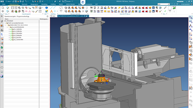
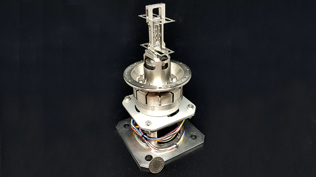
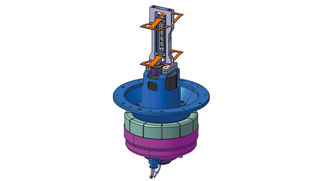
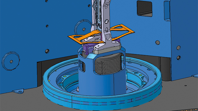
A Spectral Imaging of the Coronal Environment (SPICE) instrument aboard the Solar Orbiter will observe both the solar disk and the corona to characterize plasma properties at and near the sun. For this instrument, Almatech designed a slit-changing mechanism. It moves the shutter by deforming parts rather than sliding along guiding tracks. “This is vital because particles created by abrasion would over time disable the optical instrument, and cleaning is impossible,” says Blecha.

Testing the digital twin again and again

For many parts, Almatech’s role is to optimize existing designs. The CHEOPS telescope structure, for instance, needed to be reduced in complexity and weight while retaining its structural strength. “Because all components we create are unique and need to function for many years without any maintenance or cleaning, development cycles take longer than in terrestrial designs,” says Blecha. “Although the shape of the baffle for the BepiColombo orbiter was given, it took us four years to arrive at the final hardware.” Almatech spent a similar period developing the slit-changing mechanism for the Solar Orbiter, although they were contracted to provide the entire development from first idea to final hardware.

The main cause for these extended development cycles is the enormous number of tests performed to deliver proof that all requirements will be met in all fathomable situations over the entire lifecycle of the components. Within a development cycle, several physical prototypes are built and tested as well, but Almatech performs the vast majority of these tests in the virtual world using a digital twin of the component under scrutiny. For this purpose, the space-grade equipment designers use Femap™ software from Siemens Digital Industries Software in conjunction with the Nastran® solver to simulate performance, starting at very early phases of product development. “The various model analyses provide proof to clients and authorities that the complex devices will perform as required under the anticipated conditions,” says Blecha. “They are also instrumental in our efforts to reduce mass without compromising stability.”

×