
TOP QUALITY AND STRIKING DESIGN

Product: HandySCAN 3D
Industry: Automotive and Transportation

Aftermarket: 3D scanning as a preliminary step in the production of prototypes and samples of accessories for custom bikes

ABM Fahrzeugtechnik GmbH has been developing high-quality accessories for motorcycles of all the established brands with passion for over 30 years. Their focus is on ergonomics, modern technology and German safety standards. At ABM, unsurpassed quality meets striking design for ergonomic driving fun. Under the umbrella of ABM Fahrzeugtechnik GmbH, the WUNDERKIND custom brand develops premium accessories for custom bikes – such as motorcycles by Harley-Davidson, Triumph, Indian, Victory and others.
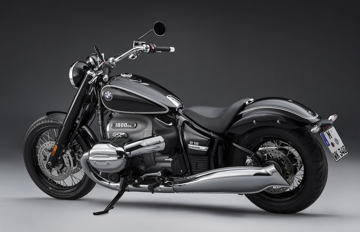
Motocicleta negra BMW R18 de 1800 cc

Rear fender conversion of a BMW R18

A complete conversion was required for the rear of the newly launched BMW R18. Instead of the original rear fender, a narrow, tight-fitting fender, which can be mounted on the rear wheel swing arm using retaining struts, was required. The original seat was removed and replaced by a free-standing seat.

In order to attach the license plate, an adapter also had to be designed to make it possible for a license plate holder frame to be mounted on the side of the swing arm. To this end, the motorcycle was first scanned completely and then without the original parts with the Creaform HandySCAN 3D scanner. Particular attention was paid to the exact position of the attachment points on the frame and the swing arm where the parts developed by ABM would later be mounted. Thread positions (M6 –M10) and hole spacing had to be captured with the utmost precision.
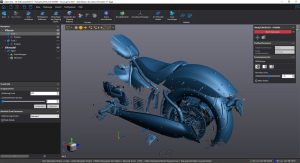
Escaneo 3D de malla azul de motocicleta en VXScan
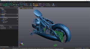
Modelo CAD 3D azul de motocicleta en VXmodel

The scanned data could then be exported to the Solid Edge design program and used there as a basis for the design. The prefabricated fender was also scanned and placed in the assembly, concentric to the wheel. The struts and adapters could be designed directly on the model and then printed to be checked.

The position of the free-standing seat could be moved in the model and optimally aligned without the need for multiple mounting and dismounting of the individual parts. After the printed parts had been checked, production of the prototype and sample could begin immediately.
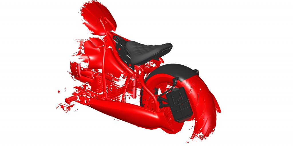
Modelo CAD negro y rojo del asiento de motocicleta de BMW R18
Scan imported into Solid Edge (red) and new rear fender including license plate holder (black)
Below: Motorcycle with scan data

Process improvement

Before scanners were used, it often took a long time to record all the data and to measure and document components, which meant the customer’s vehicle had to stay on site for a long time. With the Creaform scanning system, data is quickly recorded and documented. Components can often be prepared and printed digitally. All that is required is to have the vehicle in-house again for assembly and testing of the printed or manufactured parts. There are no unnecessary journeys between the workshop and the design office. By and large, the development process up to the finished product is significantly shortened, which saves time and money.

Another advantage is that the archived data can be used for further developments at any time without the vehicle having to be physically present.

Before the HandySCAN 3D scanner was acquired, measurements were made manually at ABM using calipers, measuring rods and measuring tapes. The procedure was extremely lengthy and the measurement results inaccurate, so that subsequent work on the model had to be performed repeatedly and 3D printing had to be carried out several times.

With this initial yet common measurement method, the project described above could have been implemented, but it would have been very cumbersome and several time-consuming and costly printouts would have been necessary due to trial & error. In addition, customer vehicles would have had to be available for a long time to implement the development.

ABM fully appreciates the advantages of HandySCAN 3D: highly accurate and reliable measurement results, small measurement distance (helpful in tight spaces), hardly any scan spray required (there is no need for laborious removal after scanning), easy handling of the scanner and software.
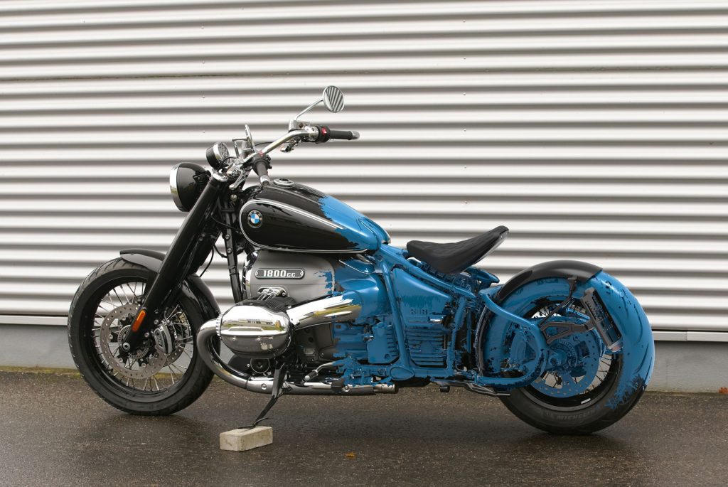
Escaneo superpuesto sobre una motocicleta BMW R18 de 1800 cc

Virtual reality and human simulation at GM

Product: Tecnomatix
Industry: Automotive and Transportation

General Motors uses virtual reality and human simulation together to accelerate early issue discovery and improve team communication

Virtual reality (VR) is an exciting technology that is proving to deliver real results across manufacturing industries. In particular, the application of VR in manufacturing process simulation is enabling the early identification of issues by allowing engineers to become immersed in their designs at one-to-one scale, discovering and solving problems before physical resources are spent. Integrating the results of VR simulation in the process workflow allows for the communication of issues effectively across physically separated teams. Because mastering VR is simple and intuitive, the technology is becoming rapidly adopted for industrial use.

Ryan Porto, Technical Specialist Ergonomics at General Motors, and Jonathan Botkin, Senior Program Ergonomist at General Motors, presented their application of VR using Process Simulate in the Tecnomatix® portfolio of digital manufacturing software from Siemens at Realize Live, Siemens’ global user conference. This blog summarizes their presentation and shows how VR is advancing efficiencies in the automotive industry.

Simulación humana GM VR

Virtual reality and human simulation at General Motors

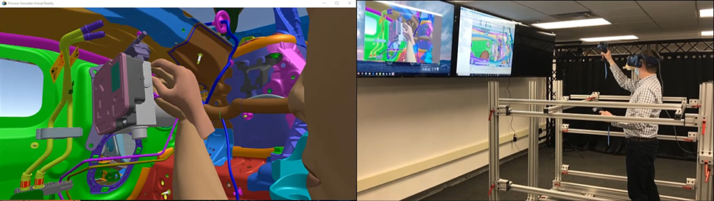
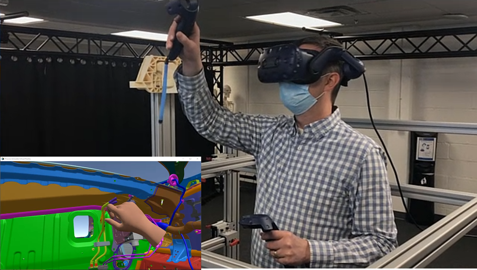
The Global Ergonomics Lab in Manufacturing Engineering at General Motors (GM) is currently conducting VR sessions using Process Simulate. The Ergonomics team uses VR to immerse product and manufacturing engineers in their designs, giving them visualization of a variety of advanced assemblies and operations in a 3D environment.

The focus of the immersive studies is to evaluate human reachability, line of sight, accessibility, and hand clearance. Immersive technology has enhanced human simulation studies during the vehicle development process for the design of safer workstations. It has also increased collaboration between product engineering and manufacturing engineering to reduce late design changes in the product lifecycle.

Virtual reality simulation

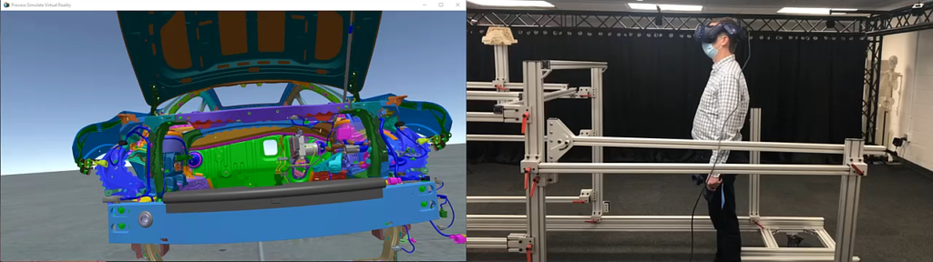
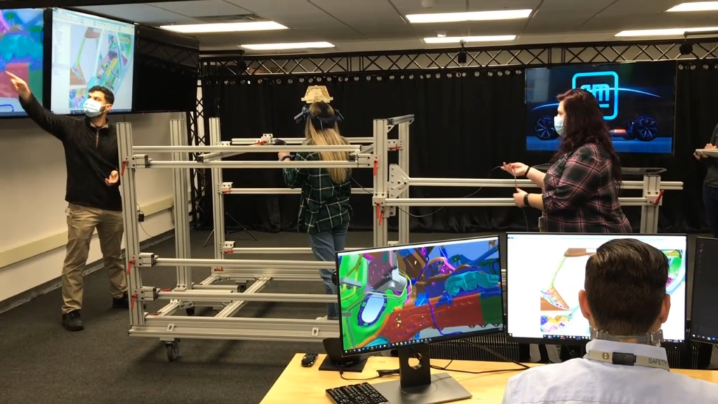
The GM team showed several video examples of how they are leveraging VR in their ergonomics lab. In one case, a subject interacts with an aluminum structure simulating the barrier and boundary awareness. The simulation mimics the hard points of a vehicle and simulates reach constraints.

The GM team added 3D printed parts to represent exact dimensions to assess accessibility and line of sight of the team member. The immersive technology helps them improve the skillset of program ergonomists and allows the ergonomist to validate their simulations in a 3D environment from a third-person point of view.

Simulación de RV de GM

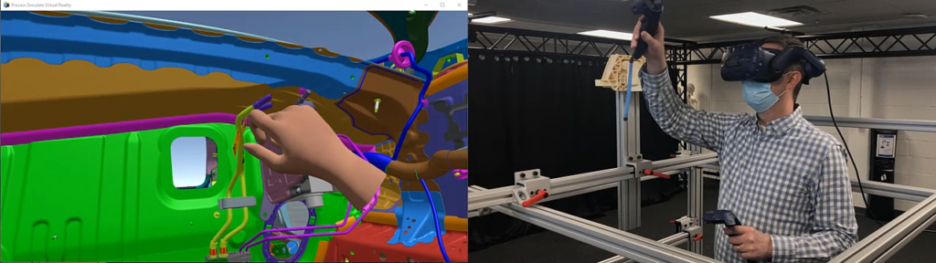
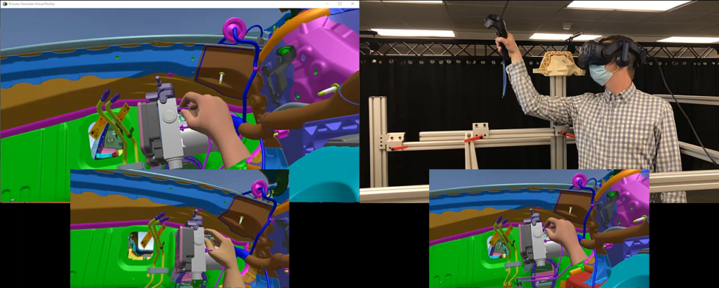
Included in the simulation is the Process Simulate “live hands” module, which gives a close-up understanding of manual assembly and hand clearance. Real-time measurement is available with an interactive ruler in the scene. Markup capabilities identify issues for the audience, and issue tracking is facilitated with notes to capture and document the issue description and record screenshots.

Virtual Reality in Process Simulate provides a realistic representation of an operation when the current plant or process does not exist today. It helps ensure consistency and reliability between evaluations across multiple programs.

Simulación de RV de GM

Motion capture capabilities

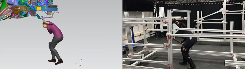
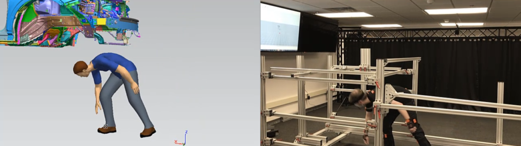
The GM team leverages motion capture capabilities provided in Process Simulate. They use an inertial motion capture solution to record the task of a female operator as she ducks under the impact beam and enters the engine compartment. Using a larger male operator, motion capture can be used to compare how a larger anthropometry would enter the engine compartment. The team can evaluate the duck under height to ensure there is accessibility to the compartment and analyze the accurate posture of a future task or operation. Motion capture enables the integration and interaction with physical structures and 3D printed parts and assemblies.

Captura de movimiento GM

Virtual reality live hands

The live hands feature of Process Simulate Virtual Reality allows the ergonomist to envision hands scaled and postured from the Process Simulate posture library. They are then able to do general hand clearance studies, validating simulations moving objects in an assembly sequence, as outlined by the manufacturing process.

Manos vivas de GM

Virtual reality line of sight

The 3D assessments in Virtual Reality allow validation of operator line of sight. For example, the GM team can see the manikin line of site to determine whether the operator could see the fittings on the brake apply module. They are then able to leverage VR to find alternative postures that were not previously considered and now provide adequate line of sight.

Línea de visión del GM

Collaboration within the VR module

In addition to the improvements of human simulation, VR has also brought tremendous value to collaboration across several groups at General Motors. During a time when working remotely has significantly increased, they have still been able to safely collaborate with key stakeholders such as designers, plant representatives, and product and manufacturing engineers. They are sharing immersive sessions and demos virtually through portals such as Microsoft Teams or Zoom. Rather than creating physical mock-ups from scratch, new vehicles can be reviewed by the members of the plant virtually.

Colaboración de GM

Sauber Engineering Chooses 3D Systems to Power Constant Innovation

Product: SLA
Industry: Automotive and Transportation

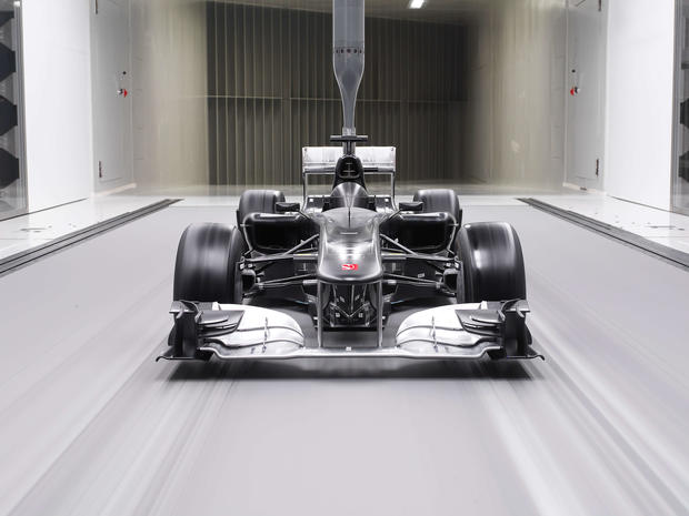
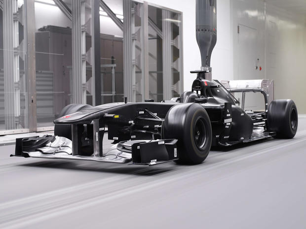
Sauber Motorsports AG has built a highly productive in-house factory to support its high demand wind tunnel operations that was enabled by a 3D Systems solutions and long-term partnership. High throughput 3D Systems equipment and solution expertise coupled with best-in-class materials provides the high-quality parts needed for Sauber to test more aerodynamic model iterations. 

Factory-Level Throughput Drives Constant Development

The pace of innovation at Sauber is relentless. In order to maximize its ability to drive rapid development on its car, Sauber Engineering has invested in an additive manufacturing machine park that is among the largest of its kind in Europe. Due to the proven throughput, quality, accuracy, and choice of best-in-class materials with 3D Systems 3D printers, this park includes fifteen 3D Systems machines across technologies. 

According to Christoph Hansen, Director of Technology and Innovation at Sauber Engineering, additive manufacturing is an integral part of every Formula One team because it provides faster access to parts than conventional manufacturing methods. “Creating something in carbon fiber can take weeks before a single part is ready,” said Hansen. “Conventionally producing the quantity of parts we need for progress would be impossible in the time we have.”  

Due to this need for speed, Hansen said lead time was the most important factor when selecting a 3D printing partner. However, it was not the only factor: “You have to produce more options to compete on the development side, but it’s not just banging out as many parts as possible. You also have to test and be sure it’s correct,” Hansen said. 

.

Best-In-Class Materials Ensure High Quality Results

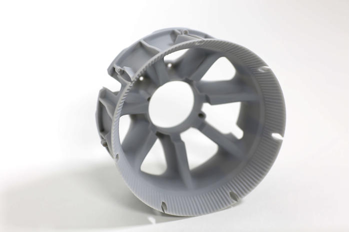
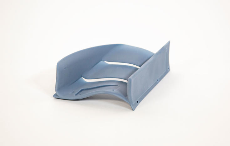
For the highest confidence in test results, best-in-class materials are necessary. At Sauber Group, part stiffness and surface finish are essential. Sauber Engineering produces an average of 100-150 3D printed part sets daily using 3D Systems machines. Of these, eighty- to ninety percent are SLA parts for wind tunnel testing that are printed using a selection of Accura SLA materials, including:   

  • Accura® HPC material, a high-speed, high-rigidity engineered nanocomposite  
  • Accura® Bluestone material, a composite material for stable, high stiffness parts  
  • Accura® Xtreme material, an ultra-tough grey plastic 

Combined with Sauber Motorsport’s confidence in the quality of Accura materials, this high level of daily part production is critical to the team’s progress and ultimate success. “On each cycle we normally find an improvement,” said Reto Trachsel, Head of Aero Design at Sauber Motorsport, “and if you can now do 50 cycles it makes a big difference. The quicker we can produce the parts, the quicker our development cycles are, and the more progress we can make in our aerodynamics.” 

Proven Quality Machines

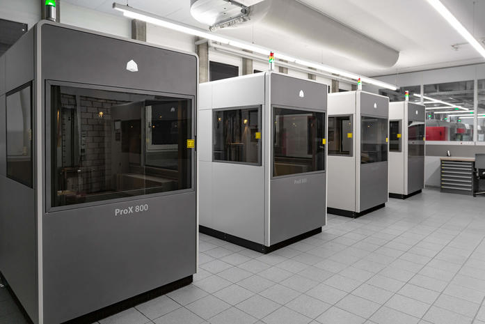
Sauber Engineering uses 3D Systems ProX® 800 printers to produce its SLA parts. This large-scale SLA printer features a maximum build envelope capacity of 650 mm x 750 mm x 550 mm (25.6 in x 29.5 in x 21.65 in), and delivers high accuracy and precision. By using two laser spot sizes per layer, the ProX 800 maintains high print speeds without compromising feature details. 

Beyond parts for wind tunnel testing, Sauber Engineering uses SLA to produce carbon fiber tooling and SLS for a variety of purposes, from miscellaneous jigs and tooling to low-volume, end-use parts for the car itself. Sauber Engineering uses additive manufacturing for end-use part production based on a combination of the convenience, complexity, and economics offered by this technology for low-volume parts like ducting, electronic boxes, and pit-stop equipment, and uses a proprietary carbon-reinforced SLS material.  

According to Hansen, the machine architecture of 3D Systems’ SLS was the deciding factor in choosing this equipment because 3D Systems’ SLS machines use a roller mechanism to lay down subsequent layers of material instead of a wiper. This method delivers a smooth and fully flattened layer of material, whereas a wiper mechanism can agitate the material and sometimes result in system crashes. 3D Systems’ roller method compacts the powder, resulting in uniform layers that deliver stronger parts. 

Nonstop Productivity Fuels Innovation

In the highly competitive world of Formula One, making constant progress in the face of ever-tightening regulations is a challenge. Sauber Engineering overcomes this challenge by using 3D Systems’ proven technologies to maximize its capabilities. An in-house factory of 3D Systems’ machines gives Sauber Engineering high throughput productivity, high-quality parts, and best-in-class materials selection to keep pushing development faster and farther. Using the expertise it has gained using additive manufacturing in motorsports, Sauber Engineering offers part manufacturing to customers in diverse industries

Producto: SLA
Industria: Automotriz y Transporte

Sauber Motorsport AG ha construido una fábrica interna de gran productividad para respaldar sus operaciones de túnel de viento de alta demanda facilitada por una asociación para soluciones de 3D Systems a largo plazo. La experiencia en soluciones y equipos de alto rendimiento de 3D Systems, junto con los mejores materiales de su clase, proporcionan las piezas de alta calidad necesarias para que Sauber pruebe más iteraciones de modelos aerodinámicos.  

El rendimiento a nivel de fábrica impulsa el desarrollo constante

El ritmo de la innovación en Sauber es implacable. Para maximizar la capacidad de impulsar un desarrollo rápido en su automóvil, Sauber Engineering ha invertido en un parque de máquinas de fabricación aditiva que se encuentra entre los más grandes de su clase en Europa. Debido al rendimiento comprobado, la calidad, la precisión y la selección de los mejores materiales de su clase con las impresoras 3D de 3D Systems, este parque incluye quince máquinas de 3D Systems en diversas tecnologías. 

Según Christoph Hansen, director de tecnología e innovación de Sauber Engineering, la fabricación aditiva es una parte integral de todos los equipos de la Fórmula Uno, ya que proporciona un acceso más rápido a las piezas que los métodos de fabricación convencionales. “Crear piezas en fibra de carbono puede llevar semanas”, dijo Hansen. “Producir de manera convencional la cantidad de piezas que necesitamos para progresar sería imposible en el tiempo que tenemos”.  

Debido a esta necesidad de velocidad, Hansen dijo que el tiempo de entrega fue el factor más importante al momento de seleccionar un socio de impresión en 3D. Sin embargo, no fue el único factor: “Debemos producir más opciones para competir en el aspecto del desarrollo, pero no se trata solo de crear la mayor cantidad de piezas posible. También debemos probarlas y asegurarnos de que sean correctas”, dijo Hansen. 

.

Los mejores materiales de su clase garantizan resultados de alta calidad

Para tener la máxima confianza en los resultados de las pruebas, se necesitan los mejores materiales de su clase. En Sauber Group, la rigidez y el acabado de la superficie de las piezas son fundamentales. Sauber Engineering produce un promedio de 100 a 150 conjuntos de piezas impresas en 3D a diario con las máquinas de 3D Systems. De estas piezas, del ochenta al noventa por ciento son piezas de SLA para pruebas de túnel de viento que se imprimen con una selección de materiales de SLA Accura, entre los cuales se incluyen:   

  • Material Accura® HPC: un material nanocompuesto de alta velocidad y rigidez  
  • Material Accura® Bluestone: un material compuesto para piezas estables de gran rigidez  
  • Material Accura® Xtreme : un plástico gris ultrarresistente 

Junto con la confianza de Sauber Motorsport en la calidad de los materiales Accura, este alto nivel de producción diaria de piezas es fundamental para el progreso del equipo y el éxito definitivo. “Normalmente, encontramos una mejora en cada ciclo”, dice Hansen, “y si ahora se pueden hacer 50 ciclos, esto marca una gran diferencia. Cuanto más rápido podamos producir las piezas, más rápidos serán nuestros ciclos de desarrollo y más progreso podremos hacer en nuestra aerodinámica”. 

Máquinas de calidad comprobada

Sauber Engineering usa las impresoras 3D Systems ProX® 800 para producir sus piezas de SLA. Esta impresora SLA a gran escala tiene una capacidad interior de impresión máxima de 650 mm x 750 mm x 550 mm (25,6 pulgadas x 29,5 pulgadas x 21,65 pulgadas), y ofrece alta precisión y exactitud. Al utilizar dos tamaños de puntos láser por capa, la impresora ProX 800 mantiene velocidades de impresión altas sin comprometer los detalles de las características. 

Más allá de las piezas para las pruebas de túnel de viento, Sauber Engineering utiliza SLA para producir herramientas de fibra de carbono y SLS para diferentes propósitos, desde plantillas y herramientas misceláneas hasta piezas de uso final de bajo volumen para el propio automóvil. Sauber Engineering utiliza la fabricación aditiva para la producción de piezas de uso final en función de una combinación de comodidad, complejidad y economía que ofrece esta tecnología para piezas de bajo volumen, como conductos, cajas electrónicas y equipos de parada en boxes, y utiliza un material de SLS patentado reforzado con carbono.  

Según Hansen, la arquitectura de la máquina de SLS de 3D Systems fue el factor decisivo a la hora de elegir este equipo, ya que estas máquinas utilizan un mecanismo de rodillo para colocar las capas posteriores de material en lugar de un limpiador. Este método proporciona una capa de material lisa y totalmente aplanada, mientras que los mecanismos de limpieza pueden agitar el material y, a veces, provocar bloqueos en el sistema. El método de rodillo de 3D Systems compacta el polvo, lo que da como resultado capas uniformes que ofrecen piezas más fuertes. 

La productividad ininterrumpida impulsa la innovación

En el mundo altamente competitivo de la Fórmula Uno, es todo un desafío progresar de forma constante frente a las regulaciones cada vez más estrictas. Sauber Engineering supera este desafío con las tecnologías comprobadas de 3D Systems para maximizar sus capacidades. La fábrica interna de máquinas de 3D Systems permite que Sauber Engineering tenga una productividad de alto rendimiento, piezas de alta calidad y la mejor selección de materiales de su clase para seguir impulsando el desarrollo de forma más rápida y prolongada. 

An introduction to Composite Structures, with Elston Engineering Services

Product: NX
Industry: Marina

We live in a world where nothing stands still. Companies and individuals across the world continue to push the boundaries of composite structures. After all, it was an engineer, not a scientist, that first set foot on another world. Elston Engineering Services (or EES) are most certainly classed in that bracket of innovators. Based in Knebworth in the UK, EES operate in the world of mechanical engineering services. The company specializing in the development of fibre reinforced plastic composite structures. Ron Elston, Managing director, proudly owns the company. Ron has a wealth of experience spanning over an illustrious 60-year career. His career began as an apprentice draftsman at ML aviation, before eventually overseeing the creation of small integrated circuits and large earth station antennas. Rons’ varied experience means he is considered a specialist within mechanical engineering and composite manufacturing.

To provide context, composites are a combination of non-metallic and metallic materials to create a structure, or range of structures. These structures create strong, lightweight, stiff and low-density components. These components lay the groundwork to create incredibly strong assemblies across a wide range of sectors, including architecture, automotive and aerospace to name a few. It’s an approach which has accelerated the capabilities of society to take our engineering capabilities to the next level.

21st century advanced manufacturing and composite applications; how did we get here?

There was a time when composite manufacturing applications were unable to meet the needs of many companies. Companies had a broad understanding of how new processes and materials would revolutionize the manufacturing workflow to include composites. The problem was, companies weren’t pro-active enough in order to facilitate change.

Ron had an opportunity to merge the testing and analysis of composite structures with the design office during his time at the Marconi Research Centre. Why was this so important at the time? It enabled a specialist like Ron to implement an integrated approach; whereby one team oversaw conceptual design, geometric design, structural analysis, tool creation, part creation and testing. By connecting the dots, composite manufacturing companies were able to achieve greater product innovation to improve production efficiencies. In addition, companies reduced the time to the final iteration, whilst simultaneously pushing the capabilities of their respective industries forward.

Technology was a gamechanger for composite structures

Ron’s experience contributed to a change to processes which resulted in improvements within advanced manufacturing. However, it was the improvements in technology that really pushed the industry into a new era. Modern day capabilities means graphical analysis is completed at a much faster pace. In addition, multiple composite materials can be handled simultaneously; mainly due to improvements we have seen in computer hardware performance and storage.

Shock and vibration studies are now more accurate than they’ve ever been; when you combine all these elements, the user is receiving far more real-world data than previously. Teams who have the experience and/or a knowledgeable will really pay dividends. Composite manufacturers are able to reduce mass, cost and production times for their structures. As a result, the same manufacturers are ultimately reducing their lead time to market.

Sustainability in composite manufacturing

Processes and technological innovations have continuously pushed industry standards to where we are today within composite manufacturing. However, a global transition towards a more sustainable society is needed; composite manufacturing is not immune to this.
Thankfully, composite manufacturing companies are already considering the practicalities of implementing sustainable technologies into their workflow. Companies are beginning to reclaim carbon fibre from decommissioned, out-of-use products in some instances. In addition, there’s been a switch towards the use of thermoplastics as opposed to thermo-setting plastics. Thermosetting plastics for composites typically incorporate one use epoxy resin, Thermoplastics such as polyethylene don’t have this problem; their chemical structure means that they can be re-melted and taken back out of composite structures for re-use. It’s essentially an early stage of a ‘circular economy’ within the composite manufacturing industry.

Fibre-reinforced plastics can produce structures with strength to weight ratios greater than traditional materials, such as steel and aluminium. Reinforcing the thermoplastics using either re-used carbon fibre or ‘virgin’ fibre can achieve strength and stiffness properties approaching those achieved with thermosetting composites. We are seeing continuous improvement of raw materials to create strong products, whilst not compromising on quality and reducing carbon emissions in parallel. This is truly the start of composite manufacturers recognizing the dangers posed by carbon emissions moving towards a more sustainable model for the future.

Why Siemens for composite structures?

For someone with Rons’ experience, using a powerful software application is just as important as having a strong understanding of the science behind composite structures. 50 years in the industry means Ron has seen, used and mastered a range of software applications. It is therefore testament to Siemens that NX continues to be the package of choice for Elston Engineering Services. Why is this the case?

The integrated approach of Siemens NX

Ron believes that Siemens has an integrated approach with NX; different features with different purposes are packaged into the same application to enable users to stay on one platform for their whole workflow. Design engineers can lose precious time during their workflow exporting datasets to another application, if their primary application doesn’t come equipped with the correct features they need for their use case. Siemens NX eliminates this problem. Factoring in a consistent development strategy which add a range of features into future NX releases lays the groundwork for NX to meet the needs of multiple companies across a range of industries.

Understanding the science behind composite structures

The user may have a strong understanding of the science behind composite structures. They then need to have the tools available to accurately simulate the science within their application. It’s an important aspect to any application when analyzing how a range of composite structures will behave in real-world scenarios. This is especially true when the scenario becomes extreme and place enormous external pressures on the structures! NX accurately analyzes composite and metallics structures in accordance with real-world scenarios. It’s a feature that came into its own when Ron developed radar antennas with EASAT for use in intense weather zones.

Biesse Group implements digital transformation with Teamcenter

Product: Teamcenter
Industry: Industrial Machinery

A company that digitally transforms successfully becomes a digital enterprise

Digital transformation refers to the adoption of data and digital solutions for business activities and processes. It engages people with digital workflows to promote the full advantage of technology investments across an organization. Digital transformation is more than just replacing manual processes with digital processes – the expected outcomes are cultural change and the adoption of re-imagined processes that take full advantage of well-defined digital strategies.

Global leader in processing machines and systems

Biesse Group is a global leader in wood, glass, stone, plastic, and metal processing technology. Biesse Group’s investments in research and development total €14 million annually, and the company has more than 200 registered patents. The company has 12 industrial sites, 39 subsidiaries, 300 agents and selected resellers, and a 90 percent export share. Founded in Pesaro in 1969 by Giancarlo Selci, the company has been listed in the Star segment of the Italian Stock Exchange since 2001. The current global workforce is 4,100 employees.

Biesse Group is gradually transforming from a machinery and system manufacturer to an organization that offers a wider portfolio of innovative services, helping customers who join the Biesse world to increase their productivity and performance.

Biesse Group identificó la tecnología PLM como un pilar del proceso de transformación digital.

Challenges

  • Digitize, optimize and improve the quality of product development projects
  • Deliver product information to all stakeholders in different business areas and roles
  • Implement a single source of data to feed other applications (ERP, IoT) automatically

Key to Success

Implement Teamcenter as a scalable PLM platform integrated with other enterprise systems

Italian manufacturer of processing machinery implements digital transformation with Teamcenter

Result

  • Established a unified platform to manage and share product information
  • Structured information to support searching and browsing
  • Reduced CAD data management time
  • Reduced product technical information retrieval time by 10 to 20 percent

With Teamcenter, we found a solution that offered all the capabilities we needed. The platform is open to future extension towards other modules and applications, so it offers solid confidence in the long term.

Davide Andreatini, Technical Manager, Machining Center Business Unit, Wood Division Biesse Group

Breathing new life into classic cars: scanning in perfect 3D down to the tiniest parts

Product: Artec Space Spider
Industry: Automotive and Transportation

Classic-Car.TV digitizes a unique 1937 Ford Eifel with Artec 3D scanners at the MakerSpace innovation center of the Technical University of Munich

How can you capture the current state of a very rare classic car and take accurate measurements of it in order to preserve it for posterity and ensure spare parts can be made in the event of an accident or damage? The team at Classic-Car.TV is no newcomer to tasks like these. Passionate about everything related to old-timers, they publish articles, photos and videos on the Classic-Car.TV website to give their audience the big picture of the classic car world. Classic-Car.TV produces new stories every week, reaching around 300,000 international readers a month.

Objectives and advantages of using 3D scanning for classic cars

The Classic-Car.TV team is now working on developing a database of classic car 3D models, one of which is a 1937 Ford Eifel. The vehicle has a special Gläser chassis and is therefore considered an absolutely unique piece.

Ford Eifel, prepared for scanning. Targets were used on large featureless surfaces to ensure better tracking

Until recently, old-timers were captured manually using stencil frames: a frame was placed around the vehicle and graphically scanned slice by slice. Wooden skeletons were created from the resulting cross-sections to reproduce the vehicle’s shape. Although this method is quite popular, it is expensive, time-consuming and not always accurate enough.

Using 3D scanners for this task is proven to save time and money, delivering more accurate results compared to the traditional method. Scans of individual parts can be used for reverse engineering, where parts are examined and often modified in order to produce spares. This is especially important for unique cars like the Ford, in case they are damaged. This car is missing its retractable top, which can now be recreated. In addition, the owner of the car wanted to document its condition as accurately as possible, which included taking 3D measurements. The data can also be used for 3D printing – a 1:4 model of this Ford has already been created.

Artec 3D: Cooperation with MakerSpace makes exciting projects happen

The digitization of the Ford Eifel was facilitated by the MakerSpace high-tech workshop, based at UnternehmerTUM, which is the innovation center of the Technical University of Munich. Housed on 1,500 sq m, MakerSpace features various manufacturing areas for processing metal, wood, textile and other materials using modern equipment. The Classic-Car.TV team came to the workshop in order to 3D digitize the Ford with Eva and Space Spider scanners, provided to MakerSpace by Artec 3D and supported by Artec Gold reseller KLIB.

“Our expertise lies in the presentation of restoration methods for classic cars,” said Kay MacKenneth, editor-in-chief of Classic-Car.TV. “Modern technology is becoming more prevalent here.”

Scanning the lead frames

3D scanners deliver high-quality data down to the smallest detail

The team used the Eva and Space Spider handheld 3D scanners to collect as much data on the 80-year-old Ford as possible. The more information about the body of the car, the easier it is to put scans together for a complete 3D model. On the other hand, not too many scans should be made: each scanning session generates a bulk of data, which requires the use of powerful computers.

It proved helpful that the body of the Ford was covered with matte anti-corrosion primer and has no glossy finish – this spared the team of the need to use anti-glare spray, making scanning easier. The Ford’s body, interior, wooden frame and the ladder frame on which the body rests were scanned with Artec Eva. This allowed for acquiring accurate digital measurements and locating missing stiffeners in order to make them separately later. But that alone was not enough: the old-timer was disassembled so the team could scan its hard-to-reach parts. That’s where Space Spider, an ideal tool for detailed digitization, came into play: It captured individual parts in extremely high resolution.

Scanning the interior of the Ford

“Working with Artec 3D scanners was a completely new experience for me and it opened up a whole new world of possibilities,” said Kay MacKenneth. “In the past, you had to measure a classic car with templates and build appropriate models. This would take months and there was the risk of ending up with deviations. In my opinion, a 3D scanner should nowadays be part of any advanced classic car garage.”

Processing scans in Artec Studio

Individual scans were aligned and fused in Artec Studio 3D modeling software. During data processing, scans were checked for possible holes. The scanning of the Ford went smoothly, and retouching had to be applied only to a few corners and cavities that were too angular to capture. At the end of the process, a point cloud, a polygon model and a texture dataset were created.
The comprehensive 3D data makes it easy to proceed with the restoration of the car. The 1:1 model can now be used to create 3D prints, sheet metal dies and spare parts. Thanks to the Artec 3D scanners, the one-off vintage car has been preserved for posterity, car fans and its owner.

“The scope of work is huge, and the scan results will certainly save months of work,” said Kay, who at the end of August 2017 presented the original model under the motto “Future Meets Past” at the Concorso Competizione Sportivo exhibition in Munich.

3D-model of the Ford

Classic-Car.TV: Further 3D scanning projects

“Together with MakerSpace and Artec 3D, we are working on several cases in which we can show how high-tech methods can be integrated into traditional professional restoration,” said Kay. “This begins with the reconstruction of parts and extends to mold-making and capturing entire vehicle shapes in order to be able to recreate the vehicle in case of damage. This is very important, especially for rare vehicles.”
Speaking about his next projects, Kay mentioned scanning Fiat 600 Elaborazione Frua, a unique piece constructed by Italian designer Pietro Frua. The car is missing turn signal mountings on the fenders. They had very special design and are now to be reconstructed by means of 3D scanning and reverse engineering. “We will also use the scanners for other stencil forms in chassis production in order to create illustrative material,” said Kay.
Rotor Bike Components Innovates with NX

Product: NX
Industry: Costumer Products

A history of innovation

Rotor Bike Components is a group of companies specialized in the design and manufacture of parts for medium- and high-performance bicycles. Recognized worldwide, the company has developed four main product lines – plates, potentiometers, cranksets, and bottom brackets – to which they apply maximum innovation in order to compete in a market that is constantly evolving.

With headquarters in Madrid and a presence in 47 countries, the company has branches in Taiwan, the Netherlands, the United States, and a network of more than 5,000 points of sale worldwide. Rotor Bike Components also has two distribution companies: Bikemotiv for Spain, and Rotor Benelux, which caters to Belgium, the Netherlands, and Luxembourg. In 2014, the company closed the year with revenues of €14 million (85 percent of the total coming from exports) and a team of almost 100 employees.

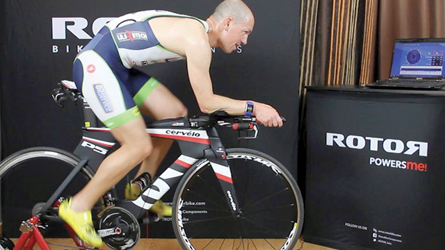
Innovation is in the DNA of Rotor Bike Components. The company’s genesis took place at the School of Aeronautical Engineers of Madrid (Escuela de Ingenieros Aeronáuticos de Madrid), where, in 1995, a group of students conceived a system of connecting rods with revolutionary biomechanical advantages called Rotor System.

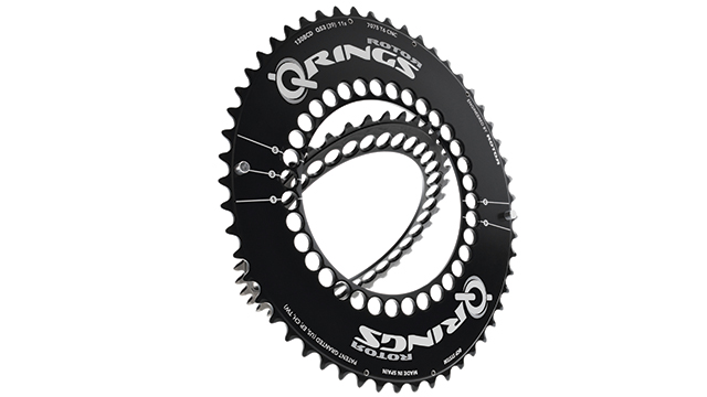
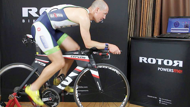
Within the business environment, they continued with other innovative releases such as RCK, a frame with a bottom bracket designed specifically to reap the benefits of the Rotor System. Most importantly, the company also created QRings, ovalized chainrings with varying drivetrain resistance to overcome the dead zone and optimize power output during pedaling. This innovation made Rotor Bike Components a benchmark company in the industry internationally.

“Traditionally, the chainrings were round, but we discovered that an oval shape improved performance and decreased muscle fatigue,” explains José Luis Sanz, director of sales at Rotor Bike Components. “We’ve become popular in the market for being able to adjust the plate and give maximum ovality in different positions, depending on where the maximum power is applied when pedaling.”

Cutting-edge technology supports growth

Innovation continues to affect the day-today operations of the company. The interest in offering solutions with the best technology to improve cycling performance is combined with the challenge of producing more than 250,000 components a year with more than 500 different references to cover their road, triathlon, mountain biking and cyclocross supply.

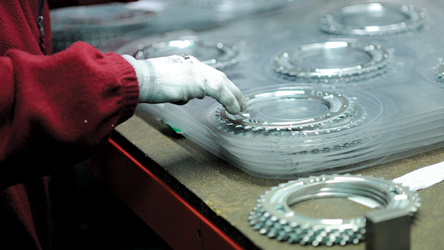
To sustain innovation, it is essential to align the efforts of Rotor Bike Components’ engineering department with manufacturing professionals from their sister company, EDR System, which is a member of the same corporate group. In the 1990s, EDR System became the first firm in Spain to use aluminum and titanium for the manufacture of bicycle parts, and is a technology leader in computer numerical control (CNC) machining.

“We move within a market of very established brands where our competitive weapon is to offer innovation. It’s important to be very agile in order to quickly adapt to change. You have to be very flexible because the average half-life of products is less than 3 years,” notes David Martínez, director of the engineering department at Rotor Bike Components.

Upgrading design technology

In 2007, the company decided to evolve its computer-aided design (CAD) system, I-deas™ software, to NX™ software from product lifecycle management (PLM) specialist Siemens Digital Industries Software in order to become more competitive. The company faced two key challenges: integrating CAD with computer-aided manufacturing (CAM), and dealing with increasing product complexity. “On one hand, there was no connection between our CAD program and the CAM program of EDR System, and, on the other, the designs were increasingly more complex, especially in addressing assembly, and we needed a tool that was more powerful,” explains Martinez. “We wanted to grow, but without the advanced technology that NX offered us, we couldn’t offer the innovation that would set us apart,” adds Sanz.

After evaluating other solutions the company opted for NX CAD, mainly due to the excellent experience of its sister company, EDR System, which uses NX CAM as a machining solution. NX was introduced to Rotor Bike Components by Análisis y Simulación, a Siemens Digital Industries Software solution partner that shared its extensive knowledge of computer-aided design, engineering and manufacturing (CAD/CAE/CAM) with the company. “We decided to also incorporate NX in our engineering department to take advantage of its design capabilities with multiple advanced features, and ensure total connection with manufacturing processes,” says Sanz.

Maximum collaboration with NX

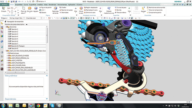
Currently 99 percent of all Rotor Bike Components’ designs are developed with NX CAD. The engineering team has six licenses, and uses the modeling and drafting tools of the software to perform their 3D design, document generation, and drawing plans for parts and assemblies. The design files are sent to EDR Systems for machining and integrated with their NX CAM system. And for new product development, the department of engineering and quality at Rotor Bike Components evaluates the manufactured models for compliance with appropriate regulations.

“Our process not only brings engineering to the work developed with NX, but also includes quality assurance and third-party companies with which we collaborate for various certifications. It also helps to incorporate elements that we do not make ourselves, such as the electronics for the potentiometers,” says Martínez. “It is critical that we can make exchanges without problems in the same file where the modeling, drawing and machining is integrated, in order to easily execute any change that is asked for, or to integrate any file that is sent to us using the extensive import and export capabilities.”

Within the company, a collaborative environment has been created using NX in which the production team also participates by designing the equipment of certain assembly lines, thanks to a floating license hosted on a corporate server. “This option is very interesting, since the production personnel use the tool in a sporadic way,” says Martinez. “It’s also used for making user manuals, for packaging design, for illustrations in patent applications, and other tasks.”

Martinez appreciates the simple, intuitive use of NX that allows for interface personalization and customization. “Análisis y Simulación gave us the proper training in order to take maximum advantage of it in a simple way,” he says.

Synchronous modeling accelerates design

The synchronous modeling tools of NX facilitate modeling, and allow for maximum speed in implementing quick changes, even without a data structure tree. “This feature together with the assurance that we can import any file extension is critical for re-use of models that we already have, especially the regulation files,” Martinez says.

Optimizing engineering with simulation

Engineering also counts on the analysis and simulation capabilities of NX computer-aided engineering (CAE) to optimize their work. “Knowing that NX was modular and that we could integrate different features according to our needs without having to change the system was a determining factor in our decision for NX. The application of the finite element method is going to continue to add more value to our processes, and it’s something that we already have.”

Australia’s Nissan Motorsports Uses Additive Manufacturing to Rev Up Performance

Product: MJP
Industry: Automotive and Transportation

We do all kinds of 3D printing work — concept modeling, verification, prototyping — but direct digital manufacturing of end-use parts is the biggest opportunity

Joe Carmody takes pride in all of his company’s 3D printing work for Nissan Motorsports (NISMO), but his biggest passion is direct digital manufacturing of parts that sometimes go from concept to the race track within a week.  It’s there, literally, where the rubber meets the road.

Direct digital manufacturing, also called additive manufacturing, is the process of 3D printing a working part layer by layer directly from a digital file.

“We do all kinds of 3D printing work — concept modeling, verification, prototyping — but direct digital manufacturing of end-use parts is the biggest opportunity,” says Carmody, president of evok3d, co-housed in the Nissan NISMO facility outside Melbourne, Australia.

evok3d produces its bespoke parts for Nissan using various 3D printers, including a 3D Systems ProJet 660Pro for conceptual and prototyping work and ProJet MJP Plastic additive manufacturing and industrial SLS systems for high-precision, functional parts that prove their mettle in the V8 Supercar Championship series.  The 15-round Australian racing series comprises two types of races — sprint and endurance — providing a diverse set of challenges for competitors.

Closing the experience gap

Most of the work occurs in the heat of the racing schedule, when adjustments are made in the so-called downtime between races, which can be anywhere from a week to four weeks. It’s not just a matter of increasing speed, but continuously improving reliability and finding out how to eliminate or reduce malfunctions — both human and machine.

“Direct digital manufacturing is ideal for racing applications, which require that cars are continuously improved and component designs iterated upon within small timeframes,” says Carmody.

For Nissan NISMO teams, the learning curve is steep and fast.  Nissan started racing in V8 Supercar in 2013.  It is competing against other teams that have raced in the series since its inception as the Australian Touring Car Championship in 1993. There’s a lot of catching up to do, and 3D printing is seen as a key tool in closing the experience gap.

Solapa de camilla impresa en 3D para Nissan Motorsports
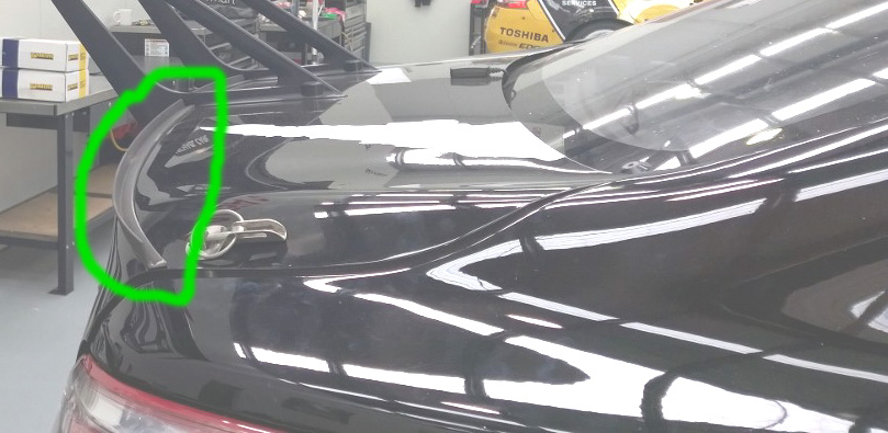
3D Printed gurney flap for Nissan Motorsports

Gurney flap in three days

Shortly after signing on with Nissan NISMO, the team faced an immediate challenge: improving the aerodynamics of Nissan Altima racecars. The rear wing wasn’t generating enough down force, which hindered cornering ability and speed. Nissan engineers went to work and developed what is known as a gurney flap — a small, curved strip extending off the rear trunk that, if done right, can dramatically improve aerodynamics.

“It’s a complex piece of geometry,” says Carmody, “with compound curves that would be difficult to manufacture using traditional modes.”

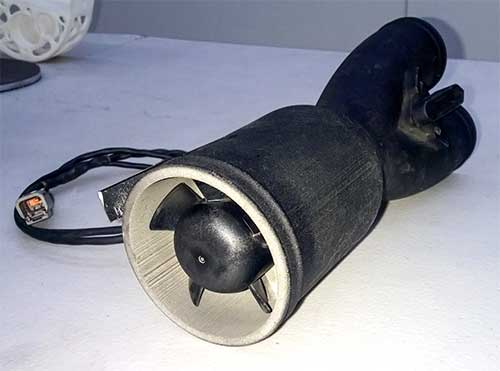
After receiving the design files from Nissan, the team went to work producing the part on the ProJet MJP 3D printer. Introduced in early 2013, the printer is designed to produce functional plastic parts and investment casting wax patterns for professional-grade design and manufacturing applications.

Keeping the air flowing

Soon after, the team put its direct manufacturing abilities to work on a driver cooling system.  Track temperatures at V8 Supercar venues can reach 100 degrees Fahrenheit and top 150 degrees inside the racecar, making it critical that the driver cooling system operates continuously and reliably.

A key component of the cooling system is the air feed to the driver’s helmet. The system comprises a dry ice box to cool the air, a filter to clean the air, a pump to generate airflow, and ducting to conduct cool air into the driver’s helmet.

evok3d’s assignment was to build a lightweight, one-piece housing for the air pump. It might sound simple, but achieving the right combination of weight, functionality and reliability isn’t an easy engineering task.

“It would be difficult to manufacture in a single piece using subtractive or injection manufacturing processes,” says Carmody, “but we were able to support the overall design goals by creating a single piece using the ProJet MJP with VisiJet M3 Black material that provides the flexibility and strength required for a production part.”

Carcasa de ventilador impresa SLS para autos de carreras NISMO
SLS printed fan housing for NISMO racecars

A different landscape

While Carmody sees direct digital manufacturing as the biggest opportunity for 3D printing, there is also great value in generating small-volume parts for concept modeling, prototyping and pre-production.

evok3d has used the ProJet 660Pro printer to create a complex mold for an air intake system and the master of a carbon fiber gear-shift cover that helps prevent drivers from accidentally putting the race car into gear during driver changes in endurance races.

Carmody believes that many of the prototypes evok3d now creates will eventually be printed as production parts as costs continue to spiral downward and new design techniques are adopted.

“Designing for 3D-printed parts presents a whole different landscape for engineers who have designed for traditional manufacturing,” he says.  “But there is great value in being able to unitize parts, eliminate assembly, reduce weight and increase efficiency through 3D printing.  Direct digital manufacturing enables you to place material exactly where you want it for maximum performance and reliability.”

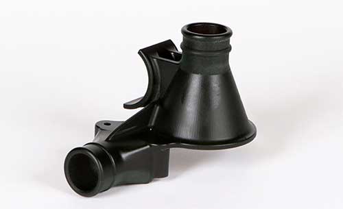
Pieza de bomba de uso final impresa en 3D de la impresora 3D ProJet MJP
3D printed end-use pump part from the ProJet MJP 3D printer

AT LOFTY HEIGHTS: 3D SCAN OF A WIND TURBINE BLADE

Product: HandySCAN
Industry: Energy

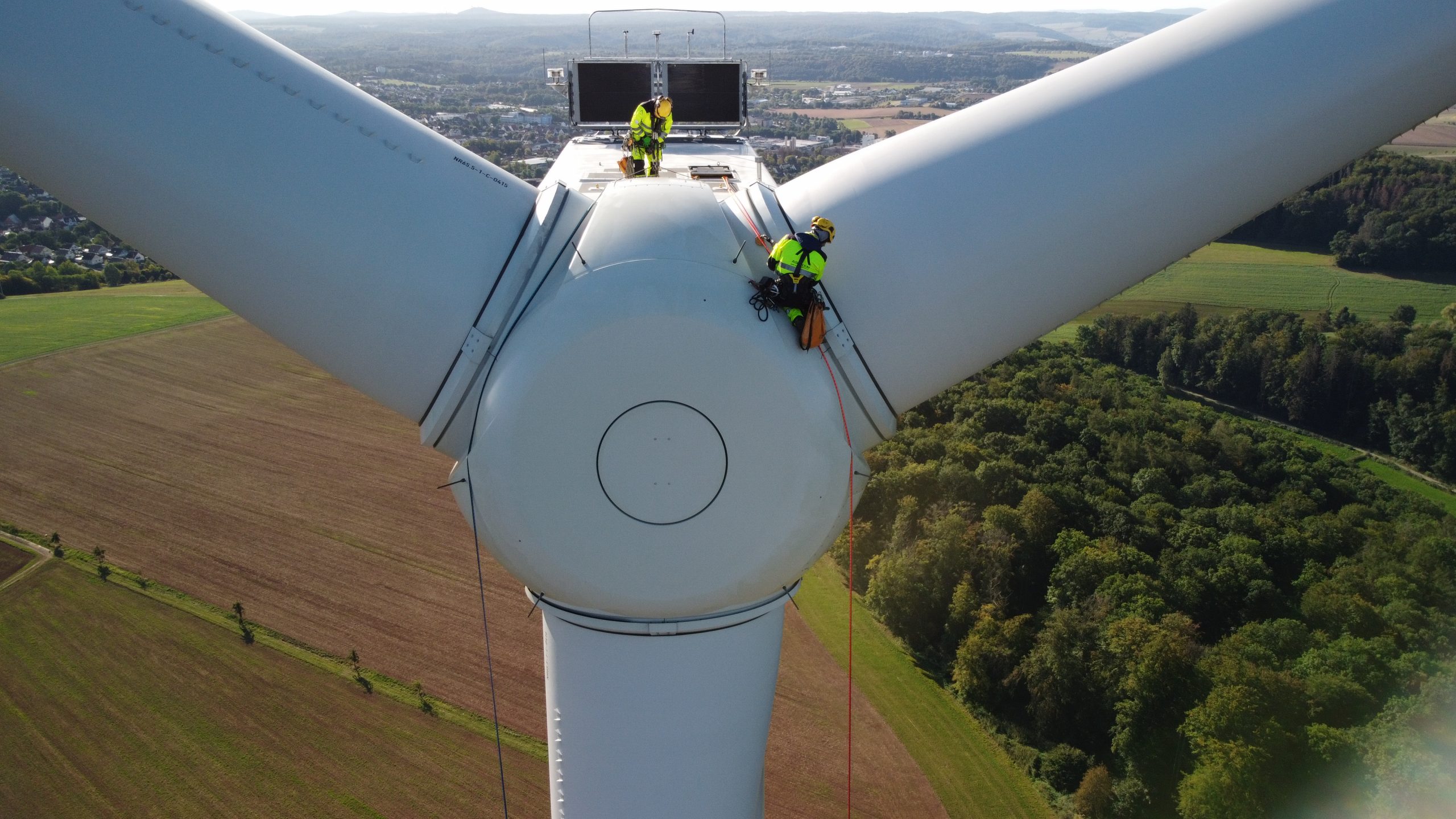
Dos empleados que trabajan encima del rotor de una turbina eólica

The maintenance of wind turbines, and whole wind farms, is a challenge. Normally wind turbines are designed to operate for 20 years. During these 20 years they are subjected to all kinds of weather conditions and heavy loads, but thanks to modern acquisition technology and advanced numerical models, such conditions can be addressed and even turned into increased annual energy production.

To optimize the production throughout their lifetime, their operating conditions must be understood in detail and then regularly maintained on this basis. The goal is to keep wear and tear under control and prevent the generation of unexpected vibrations and/or weak points that could compromise the integrity of the turbine structure and components, all while maximizing the power production.

The Spanish company Nabla Wind Power is part of the Nabla Wind Hub group, an independent service provider that offers unique and multitechnology solutions for wind farms life extension, performance improvement and maintenance optimization.

Digitalization under harsh conditions

In 2020 Nabla Wind Power was asked to extend the rotor blades of a wind turbine to increase the performance of the existing installation by 10%. To do this, the last meters of one rotor blade had to be digitalized so that the blade extension could be subsequently designed. In a first attempt, terrestrial laser scanners were used for the digitalization. But Nabla needed a considerably lower uncertainty in the measurements and therefore started to look for an alternative solution and finally asked Creaform Services to support them.

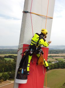
Preparación de escaneado: Escalador industrial pegando los objetivos en el álabe
Scan preparation: Industrial climber sticking the targets on the blad

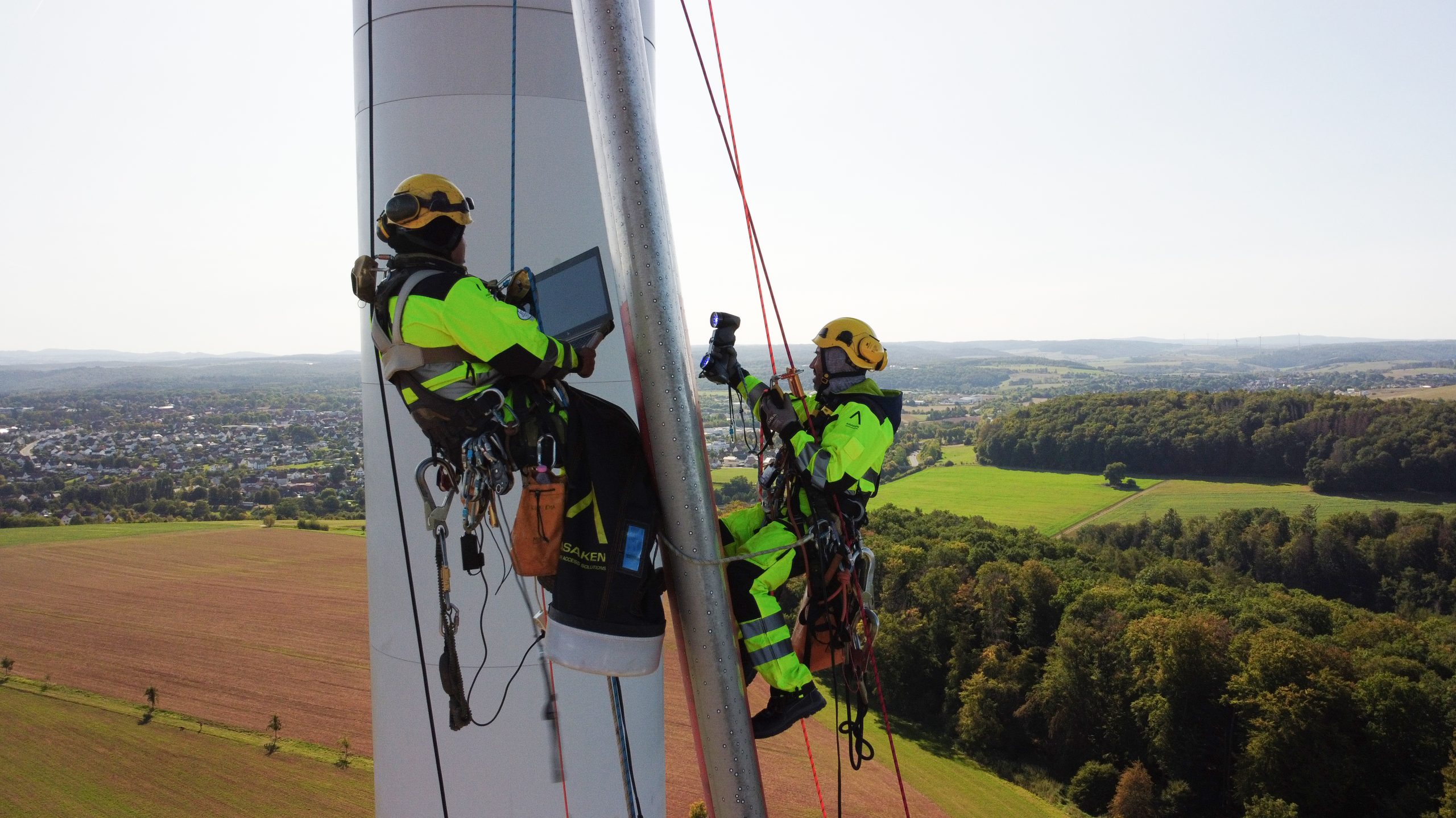
The best portable 3D scanner suited for this task was the HandySCAN 3D | BLACK. Thanks to its dynamic referencing feature, it can digitalize precisely in harsh conditions. Vibrations do not affect the results and the uncertainty of the measurements is far less than a millimeter. As the task had to be realized directly on the wind turbine, a Creaform Application Engineer trained two industrial climbers from the company Asaken and taught them how to use the HandySCAN 3D. Then the climbers went up to the top of the wind turbine at 130 meters, had to get out of the hub and rappel down to 65 meters above the ground.

The first thing to do was to stick targets on one of the rotor blades on the last 7 meters. These targets are used as reference points by the HandySCAN 3D. Then they started the scan. While one of the industrial climbers was wearing the laptop, the other was handling the scanner. Meanwhile, the Creaform Application Engineer was overviewing the scan from the ground via Teamviewer. At this height, wind conditions are always an issue and several times, it became so windy that the works had to be stopped due to the strong winds. Also, some technical issues of the wind turbine itself disturbed the scan process: for example, the rotor blocked and couldn’t be brought into a vertical position. But finally, the scan was performed successfully.

Dos empleados anclados a un álabe de turbina eólica con una cuerda utilizando un escáner HandySCAN BLACK y una computadora portátil para escanear piezas a gran altura

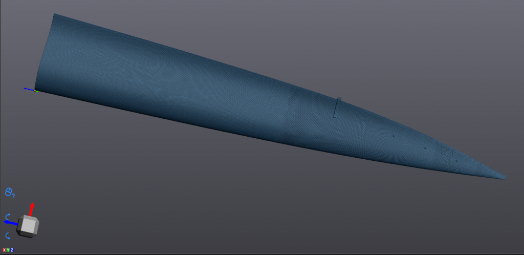
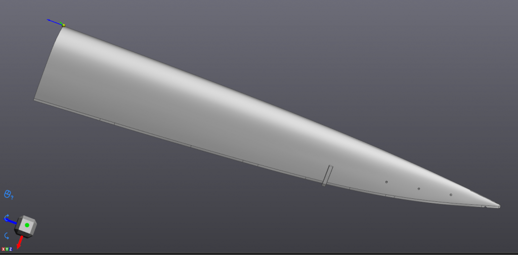
The acquisition software used was VXmodel, a module of VXelements. The generated .stl file was then transferred into CATIA for reverse engineering.

Escaneado del álabe del rotor en VXelements
Scan in VXelements with mesh visualization
CAD del álabe del rotor de ingeniería inversa en CATIA
CAD of the reversed engineered rotor blade in CATIA

Nabla’s Head of Operation, Eder Murga, was really pleased with results: “The handling of the provided service was professional, both from Creaform and Asaken. Despite the harsh conditions and many interruptions due to strong winds, everyone involved faced the change in conditions with great flexibility and, in the end, we managed to get the perfect results. A hand-held, self-referencing measuring system such as the HandySCAN 3D is the only way to carry out such a measurement in a harsh environment.”

×