Product: Artec Space Spider Industry: Design and Art
Using NX reverse engineering and polygon modeling enabled design changes to be implemented and new grips produced between races, eliminating a potential on-track distraction.
Andrew Miller, Advanced Materials Engineer Team Penske
Meeting fast-paced design requirements
Team Penske is one of the most successful teams in the history of professional sports. Cars owned and prepared by Team Penske have produced more than 600 major race wins, over 670 pole positions and 43 championships across open-wheel, stock car and sports car racing competition. Over the course of its 56-year history, the team has also earned 18 Indianapolis 500 victories, three Daytona 500 Championships, a Formula 1 win, victories in the 24 Hours of Daytona and the 12 Hours of Sebring, along with a win in Australia’s legendary Bathurst 1000 race. In 2022, Team Penske competed in the NTT INDYCAR SERIES, NASCAR Cup Series and the FIA World Endurance Championship.
In addition to racing, the company also produces racecar components and support equipment for NASCAR, INDYCAR, International Motor Sports Association (IMSA) and World Endurance Championship (WEC) racing programs.
There is a lot more that goes into winning races than just luck. Over the last decade, Team Penske has focused on developing custom steering wheel grips to help drivers behind the wheel. A custom steering wheel grip allows the driver to focus on racing, achieving maximum performance from the racecar. Clay grips are sculpted to the steering wheel frame and 3D scanned for reverse engineering, which enables Team Penske to implement a suitable design solution as fast as possible.
Team Penske achieved this by using NX™ software and Teamcenter® software, which are part of the Siemens Xcelerator portfolio business platform of software, hardware and services.
Using reverse engineering to speed up the design process
Designing these custom steering wheel grips and the necessary mold tooling is no small feat. Team Penske used to outsource the reverse engineering of the scan data, which increased costs and lead time. More recently, Team Penske used a third-party software package to reverse engineer the scan data, generate initial surface and reference computer-aided design (CAD) data. However, this data was not native to NX so making changes to the design was laborious and inefficient.
Another challenge the company faced was meeting the demands of a fast-paced racing industry. When it comes to racing, drivers are the primary stakeholders that generate results from this development. Developing custom steering wheel grips for new drivers, or implementing changes for existing drivers needs to happen within days to weeks. The fast-paced development requires Team Penske to use integrated tools to create and change designs seamlessly.
Once Team Penske realized the new reverse engineering capabilities with the Siemens Xcelerator portfolio, they set out to use NX and Teamcenter to streamline the process. Moving the reverse engineering and design to the native NX CAD system enabled a more efficient in-house design process. Using the NX CAD system helped store all data in one location with traceability in Teamcenter. Integrating the reverse engineering process into NX with the reverse engineering tools and polygon modeling has streamlined this process. Now, Team Penske can implement changes quickly in a parametric process. This is critical when dealing with multiple INDYCAR drivers, each with unique custom steering wheel grips.
Using NX decreased the design time required to implement changes compared to using third-party software packages. One example of this comes from INDYCAR driver, Scott McLaughlin. McLaughlin wanted changes to his steering wheel grips after his inaugural season with Team Penske in 2021. Using NX reverse engineering and polygon modeling enabled Team Penske to make design changes and produce new grips for McLaughlin between races, eliminating a potential on-track distraction. “A custom steering wheel grip allows the driver to focus on racing to achieve maximum performance from the racecar,” says Andrew Miller, advanced materials engineer for Team Penske.
McLaughlin went on to win three races, capture three pole positions and finish in fourth place in the INDYCAR championship during his second season in 2022.
“Using NX reverse engineering and polygon modeling enabled design changes to be implemented and new grips produced between races, eliminating a potential on-track distraction,” says Miller.
Team Penske quickly learned how to use NX and Teamcenter with help from the online resources in the Siemens Xcelerator Academy and customer support from Siemens.
Racing ahead
Team Penske reduced the design time of the steering wheel grips and molds from a minimum of three to four days to within one to two days. It eliminated outsourcing or third-party software requirements for steering wheel grip designs and used Teamcenter to improve design traceability for grip designs. Team Penske plans to continue using NX and Teamcenter to further investigate texturing and algorithmic modeling for applying textures to steering wheel grips and interface devices.
A custom steering wheel grip allows the driver to focus on racing to achieve maximum performance from the racecar.
Andrew Miller, Advanced Materials Engineer Team Penske
Product: Artec Space Spider Industry: Design and Art
Nature has always been an inexhaustible source of inspiration for people. Climbing pads mimicking the biomechanics of gecko feet, antibacterial micropattern that mimics the form and function of sharkskin, or the aerodynamics of the famous Japanese bullet train inspired by the shape of a bird’s beak – these are just a few examples of how models, systems, and elements of nature are used to solve complex human problems and design challenges.
As Janine Benyus, biologist, author, and co-founder of Biomimicry Institute famously said in her TED talk: “We are surrounded by genius. We were never the first ones to build [anything].”
Global urbanization, mass migration to cities, and new travel regulations leave us humans with a limited selection of opportunities to get in touch with all the facets, recipes, and blueprints that this greatest invention machine has to offer. However, there are places in the world where you can access thousands of authentic natural history specimens without having to go into the wilderness, fly to a remote island, or wade through impenetrable jungles, unbearable heat, or cold. One such place: the Edna W. Lawrence Nature Lab.
Edna W. Lawrence Nature Lab (photo courtesy of the Nature Lab)
Overview
Founded in 1937 by a Rhode Island School of Design graduate, long-time faculty member, scholar, teacher, and accomplished American painter, Edna Lawrence set out to, in her own words, “open students’ eyes to the marvels of beauty in nature…of forms, space, color, texture, design, and structure.”
The Nature Lab is not your typical laboratory. What started as a small collection of natural specimens that Edna picked up during her summer road trips for her Nature Drawing class in the 1920s, turned into 1,286 species (including shells, butterflies, minerals, skeletons, seed pods, and taxidermy) in 1937, and had grown to up to more than 25,000 items by the time she retired 38 years later.
Today, the Natural History Collection consists of nearly 80,000 individual specimens, which students and faculty members of RISD have unrestricted access to, whether it’s a science, art, or design project they are working on.
“There’s definitely no other department in the university or standalone place that is anything like the Nature Lab and its Natural History Collection,” said Benedict Gagliardi, Staff Biologist at the Lab. “Students can get a fully immersive experience in there – they can open cabinets and take out shells, bones, and pieces of driftwood and taxidermy animals and actually interact with them: draw, feel, move around, and spell them.”
“It’s a very welcoming environment. The notion is like: we’ll go as deep as you want to, but we aren’t going to push it on you,” said Dr. Jennifer Bissonnette, Interim Director of the Nature Lab. “And if you have questions, we have three biologists on staff that can help you dig deeper and do whatever it is you want to find out about.”
Apart from the main collection, the Nature Lab also houses collections of insects, lichens, corals, and other small-scale specimens, collections of organic and non-organic materials, living plants, rare natural history books, as well as provides access to the latest imaging equipment to explore all its variety of natural artifacts at multiple scales and dimensions. One of such imaging tools that the team at the Nature Lab added to their kit in 2015 is Artec Spider.
Adding a 3D scanner to the toolkit
“Part of what we are doing here is creating a space for the visualization to take on new directions,” said Dr. Jennifer Bissonnette, Interim Director of the Lab. “We were thinking of novel ways of appreciating those organisms, surfaces, and textures that we have here, and Artec Spider was a perfect fit because of its state-of-the-art ability to capture really fine resolution of different structures.”
Designed to scan small objects with fine details in high precision, Spider is an ideal solution for digital preservation of natural and historical artifacts in their true shape and color. Powerful, accurate, yet lightweight and easy to use, Spider became a welcome addition to the Lab’s collection of imaging equipment, alongside professional microscopes, action cameras, GPS trackers, and other tools for research and documentation of natural materials, specimens, systems, and processes.
The Nature Lab uses Artec Spider to digitize their 80K+ Natural History Collection (photo courtesy of the Nature Lab)
Since the moment the 3D scanner was available to the Lab faculty members and students, it quickly became one of the most popular tools. “There’s something encouraging in being given access to such a high-level piece of equipment and being able and trusted to use it,” said Gagliardi. “It makes that part of your project so more personal and connected to it, rather than just saying: Oh, can you scan this for me?”
Going digital
3D scans of taxidermy specimens, natural history objects, and materials that students captured with Spider at that time were initially stored on external hard drives by Gagliardi and his team and were solely available only to their creators through direct inquiry. But the whole process changed when the pandemic hit. Since students and faculty members couldn’t come to the Lab and interact with its collections onsite, there needed to be a way for them to access those specimens – at least some of them – digitally. That’s when Benedict came up with an idea to upload all the 3D scans they already had to Sketchfab, an online 3D model sharing platform, and create a Virtual 3D Specimen Library:
“When the pandemic hit, losing that sort of tactile learning was really difficult to substitute with any sort of digitized representation,” said Gagliardi. “But man oh man…that digital collection has been a huge benefit for the teachers who were struggling to digitize their curriculum. 3D scanning with Artec Spider was hugely, critically important to give that three-dimensional understanding of things.”
The Lab team decided to make all the models in the library freely downloadable, so both students and faculty staff could use the files, abstract them, and do whatever they wanted to make them their own.
Nautilus Shell 3D model made with Artec Spider
Having exact 3D replicas of various specimens and materials also allowed the team to bring a new perspective to their biomimicry classes:
“One of the topics that we’re working on in the lab is called biomimicry, in other words, using nature to inspire design solutions,” said Bissonnette. “Having a digital collection of different natural forms and materials allows us to analyze them, and take them to other software where we can start building off structures to modify for whatever design intention.”
The new approach also made it possible to lend the items that previously were available for “Lab only” use:
“In normal terms, we can lend out lots of specimens like library books: a hand-made glass box with a spread butterfly in it, for instance, certain types of shells and all kinds of small specimens,” said Gagliardi. “We have red dots on the things that you cannot take out. 3D scanning gave us the ability to lend those out in a way, so people could interact with them after hours or remotely far away. It really changed the way this lending process was working.”
Another advantage of having a digital catalog of 3D models online was an opportunity to connect to a global community of creators and researchers:
“We had so many exciting comments from people who incorporated our 3D scans in their own artworks, video game designs, and other disciplines,” said Gagliardi. “There are also biologists who helped us identify some of our specimens. For example, what we’ve always labeled as a chinchilla skull up on Sketchfab, turned out to be a muskrat skull.”
On typical workflow
During the pandemic, the scanning process had to change, too. With almost everyone working or studying remotely, it was Gagliardi who started scanning different specimens by requests from lecturers or students to replenish their newly created.
“Taking it into a virtual space suddenly became not just an interesting thing for students and faculty to be able to do, but critical to be able to still get access to the collection,” said Bissonnette.
Although each type of specimen is unique, most objects scanned in the Lab follow the same two-scan workflow.
First, an item is scanned one time around on top and the sides, then flipped over for another scan of the bottom and the sides. The team also uses a foldable light box from ORANGEMONKIE to achieve high-quality, evenly lit texture, and an electric turntable for smooth and steady scanning.
“From the first time I used it, I was blown away, especially by seeing the process of what Artec Studio software does,” said Gagliardi. “You get a raw scan and you think ‘cool, this looks like a thing that I’m scanning,’ but the end product, the finalized mesh, is so refined compared to the initial scan that I’m still in awe every time I get the final product out.”
After scanning is complete, the team processes the data using Autopilot mode in Artec Studio. Once done, the final model is exported directly to Sketchfab as is, or in some cases, first to Blender for additional post-processing. “The scans that Artec Studio puts out are pretty high quality, so often we just export the scan and we’re ready to go,” added Gagliardi.
Currently, the digital collection consists of 500-600 scans with almost 400 already uploaded and available for download on Sketchfab.
On future plans
Through launching their virtual library of 3D scanned specimens, the Nature Lab team gave access to some of the finest natural artifacts from Edna Lawrence legendary collection – and not only to the students and faculty members of the Rhode Island School of Design, but public schools and institutions who may not have access to such resources. It has also allowed them to connect and collaborate with other universities and museums that also use Artec scanners, photogrammetry, or other digitization methods.
“I continue to get comments, messages of thanks, and inquiries from professionals and non-professionals in the art and science world, out of RISD,” said Gagliardi. “Recently, a project manager from one of the world’s largest providers of museum technical services contacted me to verify that it was ok for them to use our painted turtle model for a casting project. I’m amazed by the wide reach and variety of connections this platform and unique resource has helped foster.”
Now back to training individual students how to create their own 3D models with the Artec Spider, the virtual collection continues to be of huge value to students, teachers, and other users. There are still remote courses at RISD that make significant use of the digital collection as a learning tool, and it has likewise been a valuable asset as the school expands Continuing Education programs via digital platforms to a wider audience.
“We definitely plan to continue building our remote digital resources,” said Gagliardi. “The pandemic has taught us so much about how valuable they are. We would have had a very different year with regard to our success in being remote if we hadn’t had Artec Spider.”
Product: Geomagic Control X Industry: Aerospace and Defense
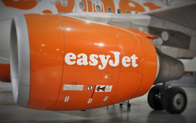
If you’ve flown anywhere in Europe in the past two decades, chances are good that you’ve flown on easyJet. This leading European low-cost airline brings travelers to more than 30 countries on 600+ routes safely and conveniently, all while offering some of the lowest fares across the continent. How do they do it? With a focus on safety, simplicity, and operational efficiency. easyJet’s engineering organization epitomizes this ethos by putting safety at the heart of everything it does and innovating to continually improve performance and reduce costs.
An easyJet Airbus A320 at the company’s maintenance hangar, where 3D scanning is being leveraged to improve and speed up aircraft damage assessments.
Minimizing Aircraft on Ground Time
One of the most important ways that easyJet can minimize delays and keep ticket prices low is reducing Aircraft on Ground (AOG) time. Unplanned AOG events happen when any of the company’s 298 Airbus aircraft are damaged or experience mechanical failures, and can be very costly — not to mention inconvenient to passengers. It’s clear that the faster a damaged aircraft can be checked, the better it is for the airline and its passengers.
“One of our biggest challenges is to try and reduce the AOG time of aircraft and maintain accurate records when damage occurs,” said Andrew Knight, Fleet Structures Engineer at easyJet. While rare, hail, bird strikes, and other events can potentially damage the wings and fuselage and require inspection before flying again. Checking damage from these types of events has traditionally been a low tech, manual, and time-consuming process that requires maintenance staff to assess aircraft damage using manual measuring tools such as rulers and vernier calipers. Worse still, interpreting the extent of any damage using this technique is highly subjective and not repeatable between staff members. easyJet’s structural engineering team went looking for a modern solution to speed things up and provide more accurate, traceable results.
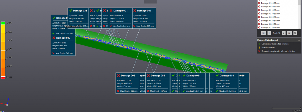
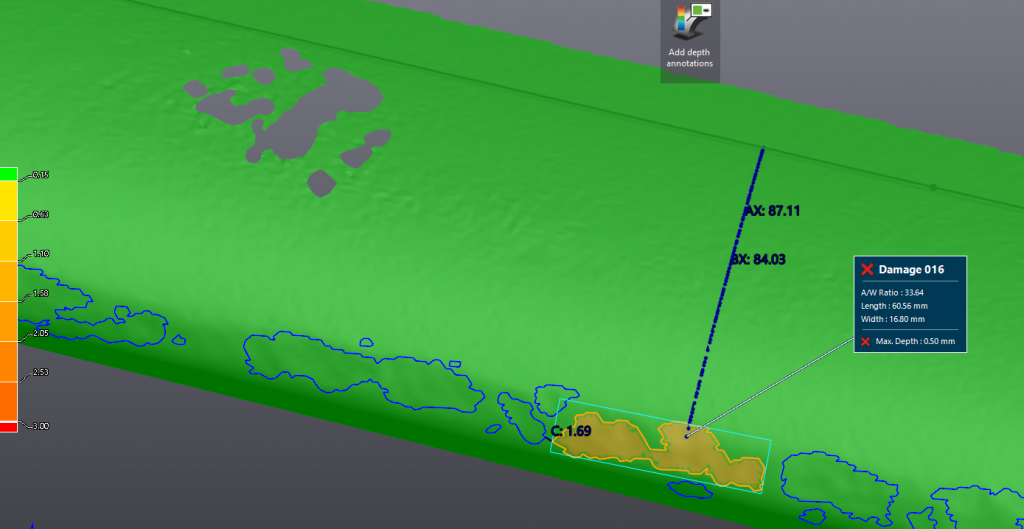
Geomagic Control X displays the results of a dent analysis, including maximum depth and distance between each dent, based on a 3D scan of a wing flap.
Repeatable, Accurate, Mobile 3D Inspection
“We’ve been looking for a system that is easy to use for the maintenance engineer but has the ability to provide more in-depth reports if required by support staff. It must be accurate, repeatable and most of all, mobile, as AOG events can occur anywhere within our network of 136 destinations across Europe,” Knight continued. “The biggest challenge was the software side because it needed to be a simple, easy-to-use interface to obtain a basic damage report, but powerful enough to provide more in-depth details in the support offices. 3D scanning should provide us with accurate, fast damage assessment with repeatable results independent of the experience of the user.”
For these reasons, easyJet turned to 3D Systems reseller OR3D, a UK firm with expertise in 3D scanning and Geomagic software. Robert Wells, a 3D scanning expert at OR3D, reported that “based on easyJet’s requirement to quickly scan large areas — such as the entire wing length of an Airbus A320 — on the tarmac, we recommended a portable handheld 3D scanner. And we knew Geomagic Control X™ was the right software because they needed an automated way to assess dents that was easy for their staff to learn and use.” With this solution, performing a damage assessment on the roughly 70 feet (21 meters) of an A320’s flaps takes just a few hours, compared to several days with wax rubbings on tracing paper, saving easyJet tens of thousands of Pounds/Euros per damage event.
The location and severity of damage is instantly recognizable during assessment of flight surfaces. Repair decisions can be made quickly and with a high level of confidence.
Instant Reporting for Fast Documentation
Once the scans are complete, easyJet engineers can get damage reports from Geomagic Control X software on the spot. They don’t need to load CAD models or align the scan data to anything else in the software, and they don’t need to have deep metrology expertise to get reliable output. Control X uses its CAD engine to automatically create idealized geometry that meets standards for surface continuity that are defined by Airbus, and measures the scanned aircraft against that idealized geometry to provide instant results. Within minutes, easyJet engineers have a consistent, repeatable, and thoroughly documented initial damage report that lets them decide what repairs, if any, are needed before the aircraft can be placed back into service.
Powerful 3D Inspection That’s Easy to Learn
easyJet has embraced Control X for large-scale damage assessments because it’s so accessible for busy engineers with many other responsibilities. Knight remarked on this specifically, saying “engineers will not use the system if it is too complex and requires in-depth software knowledge and/or extensive training.” Control X fulfills these requirements better than any other scan-based inspection software because it’s intuitive, easy to learn, and powerful enough to handle complex measurement scenarios. Anyone familiar with using 3D software can pick up Control X and get results in a matter of minutes, with the flexibility to measure what they need to, without pre-programming or inflexible macros.
What does this new, modern approach to damage inspection mean for easyJet? “We have estimated an approximate 80% savings in time to perform assessments using the 3D systems we currently have with a potential 80% savings in currency terms,” says Knight. There are additional benefits beyond reduced AOG time and better decision-making regarding repairs as well: keeping detailed damage reports, complete with accurate scan data, can help the company years from now when it comes time to sell or return aircraft to their leaseholders.
easyJet’s use of Control X is another example of how simple, intuitive inspection software helps companies ensure quality everywhere by empowering more people to measure more things in more places.
Since we integrated Plant Simulation into our program, a wide variety of companies have contacted me requesting help to fill fulltime throughput simulation positions. And with the launch of the Plant Simulation internship program, we expect that number to grow.
Robert Van Til, Pawley Professor Chair ISE Department Oakland University
Preparing engineering students for Industry 4.0
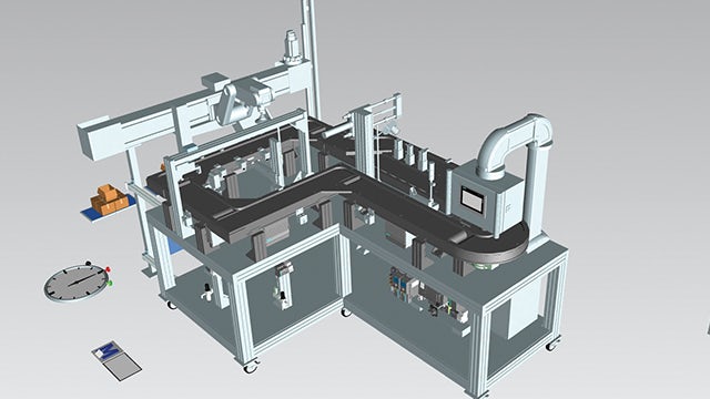
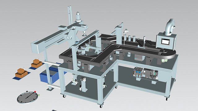
Located in Rochester, Michigan, Oakland University is a public university whose School of Engineering and Computer Science is a major driver in the institution’s growing reputation. The school’s Industrial and Systems Engineering (ISE) department was founded in 2005 and features undergraduate, masters and doctorate level programs in industrial and systems engineering, engineering management, and systems engineering.
The ISE department became a Siemens Digital Industries Software academic partner in 2011. Since then, the department has integrated several tools from Siemens Digital Industries Software’s Tecnomatix® portfolio, including Plant Simulation, Jack™ software and Process Simulate Robotics as well as solutions from the Teamcenter® software portfolio, into undergraduate and graduate engineering courses. And the ISE department is currently integrating Insights Hub, the industrial IoT solution from Siemens, along with Opcenter® suite into some courses which are all part of the Siemens Xcelerator business platform of software, hardware and services.
Several ISE department graduates have secured full-time positions with well over a dozen companies working on various aspects of Industry 4.0, with approximately 10 of those companies hiring Oakland University students for their knowledge of Plant Simulation. Due to the use of Plant Simulation and other Siemens Digital Industries Software tools, the academic partnership program has helped Oakland University develop relationships with many companies who were previously unaware of the ISE department’s programs.
Creating a hands-on throughput simulation course
After using Plant Simulation in some existing courses, the ISE department found that many students, as well as the companies hiring its graduates, suggested the development of a new course that takes a deeper-dive into the use of the tool and its application. This led to the creation of a new half-semester course titled PLM Applications – Throughput Simulation. The course combines education with some training, teaching students to operate Plant Simulation and use the tool to complete various hands-on throughput simulation assignments.
With discrete event simulation of manufacturing and other systems becoming increasingly vital to industry, the course focuses on using Plant Simulation to build, run and analyze discrete event simulations of systems and to present the results. Students learn about the creation and usage of a digital twin to reduce risk and return value. The course covers requirements analysis, model creation, validation, and a “what if” analysis.
To better serve working engineers the course is offered in the evenings. Robert Van Til, Pawley professor and chair of the ISE department says, “A large percentage of students in our masters’ programs are full-time working engineers since all graduate courses are offered in the evenings. We also get working engineers taking this course as well as other PLM-related courses as non-degree students.”
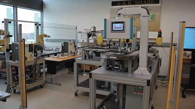
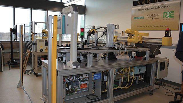
Experiential learning through the Plant Simulation internship program
Experiential learning allows students to take the concepts and techniques learned in the classroom and apply them to realworld problems in an industrial environment. Through the Plant Simulation internship program, Oakland University’s ISE students participate in experiential learning. The paid internship program consists of four parts:
The ISE department works with companies to recruit and interview ISE students to serve as a Plant Simulation intern, with the company making the final selection
The intern is paid to take the PLM Applications – Throughput Simulation course to learn Plant Simulation during the fall semester. The company also selects a throughput simulation project for the intern, in consultation with ISE faculty members, during the fall semester
The intern is paid to work part-time on the throughput simulation project under company supervision with the assistance of an ISE faculty member during the winter semester, approximately 12 to 15 hours per week. The intern works on the project either in Oakland University’s Product Lifecycle Management (PLM) laboratory or at the company’s facility while taking classes. If the intern works primarily at Oakland University, he or she will still spend time at the company’s facility to learn about the system being modeled, collect data, etc.
The intern is paid to work on the project full-time during the summer, again either in Oakland University’s PLM Laboratory, at the company’s facility or at a mixture of the two locations
The internship program was piloted during the 2018-19 school year. Plant Simulation interns were placed at an aerospace company and an automotive original equipment manufacturer (OEM).
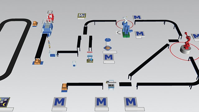
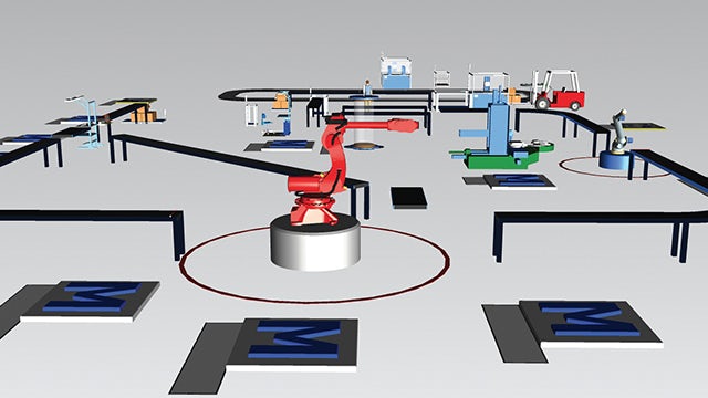
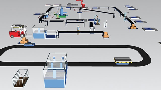
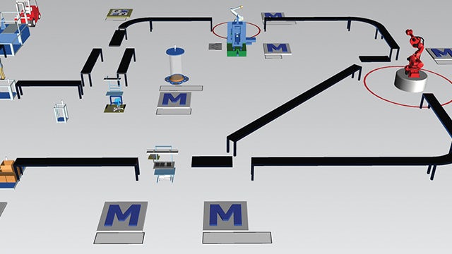
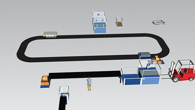
Oakland ISE undergraduate student Brianna Walters’ internship project at an aerospace company focuses on using Automated Guided Vehicles (AGV) and Mounted Robot Guided Vehicles (MRGV) to move parts and tools through a job shop type model. Walters notes, “The company initially had me using my Plant Simulation model to explore the software and its capabilities. Next, we plan to look at machine and transporter utilization.”
While Walters was originally scheduled to serve her internship during the summer of 2019, the company was so impressed by her work that they have hired her to a full-time engineering position.
Another ISE undergraduate student, Mick Packard, is interning at an automotive OEM. His project involves several steps:
1. Shadow company and Siemens team members during initial weeks, observing the business actions and practices of the group while continuing to build on knowledge of Plant Simulation and model design techniques.
2. Create a digital twin model of an engine block machining line, then validate the model to a level of statistical significance while meeting key performance standards.
3. Run pallet optimization tests and buffer sensitivity analysis using the model.
4. Design “what if” scenarios based on optimizing line performance.
5. Create a report on the project; breaking down the process of building the model, features included in the model for re-usability and continued tests, accuracy of model, results of “what if” scenarios, as well as challenges and struggles.
6. Finally, present results to company managers, team members and plant engineers. Also, provide an in-depth knowledge transfer opportunity for other company engineers on model practices/features.
“This internship has been an amazing experience,” says Packard. “It’s great to take the tools and techniques we are learning in our Oakland classes and apply them to real-world engineering problems.”
The Plant Simulation internship program is being offered to other large companies as well as to small-to-medium sized businesses (SMB). Many SMB are evaluating the value of integrating PLM tools such as Plant Simulation into their operations. The internship program offers a cost-effective way to conduct an independent throughput simulation evaluation study on a company’s existing system without purchasing a license or training existing personnel.
After the project is completed, the Plant Simulation internship program also provides companies with the option of hiring the intern, who is not only educated in discrete event simulation and trained in the use of Plant Simulation but is also familiar with the company.
The early results of the program have exceeded Oakland University’s expectations as demand for graduates with throughput simulation experience with Plant Simulation has far exceeded the supply.
“Since we integrated Plant Simulation into our program, a wide variety of companies have contacted me requesting help to fill full-time throughput simulation positions,” says Van Til. “And with the launch of the Plant Simulation internship program, we expect that number to grow.”
Plans for the future
Oakland University is considering expanding the Plant Simulation internship program into an Industry 4.0 internship program with the addition of internship opportunities that focus on ergonomics and robotics by using the Jack and Process Simulate Robotics tools, respectively. This should be relatively straightforward since the ISE department already offers handson courses on both Jack and Process Simulate Robotics.
The company initially had me using my Plant Simulation model to explore the software and its capabilities. Next, we plan to look at machine and transporter utilization.
Brianna Walters, Student, Intern at aerospace company Oakland University
Product: HandySCAN Industry: Aerospace and Defense
Lufthansa Technik AG (LHT) is a provider of MRO (maintenance, repair and overhaul) services for aircraft and has 50 locations worldwide. LHT is wholly owned by Deutsche Lufthansa AG and comprises 32 technical maintenance companies and subsidiaries in Europe, Asia and America, along with more than 26,000 employees (as of 2019).
LHT is based at Hamburg Airport. Other important German locations are the two Lufthansa hubs Frankfurt Rhein-Main and Munich as well as the Berlin Tegel Airport (Line Maintenance) and Schönefeld (C-Checks).
Control of Material Expansion
The ARC® – Airframe Related Components division overhauls and repairs fan reversers, engine cowlings, flight controls, aircraft noses (radomes), and other secondary structure composite components. In addition to maintenance work, repair, developments, all types of material support, and logistics solutions are provided. These services are offered for civil aircraft and nearly all popular aircraft types.
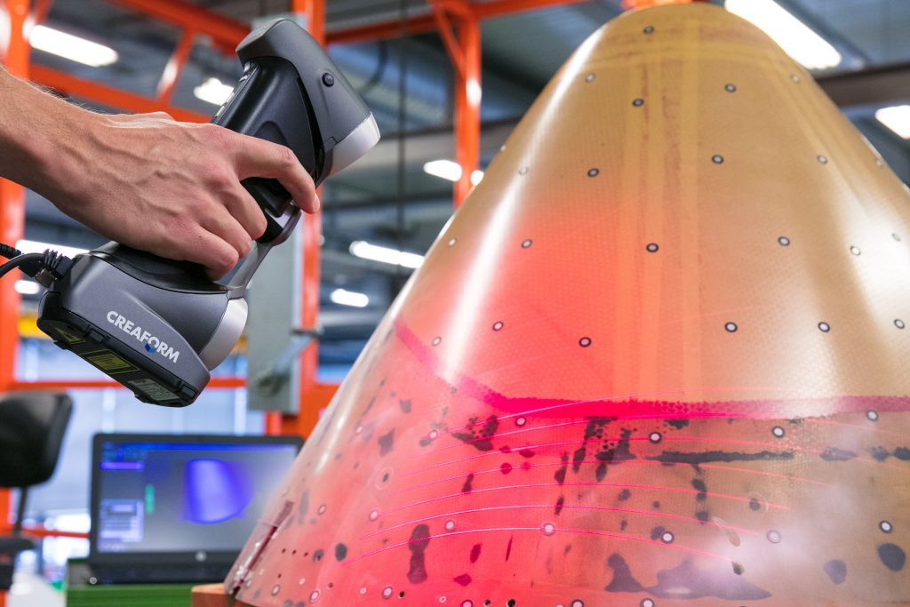
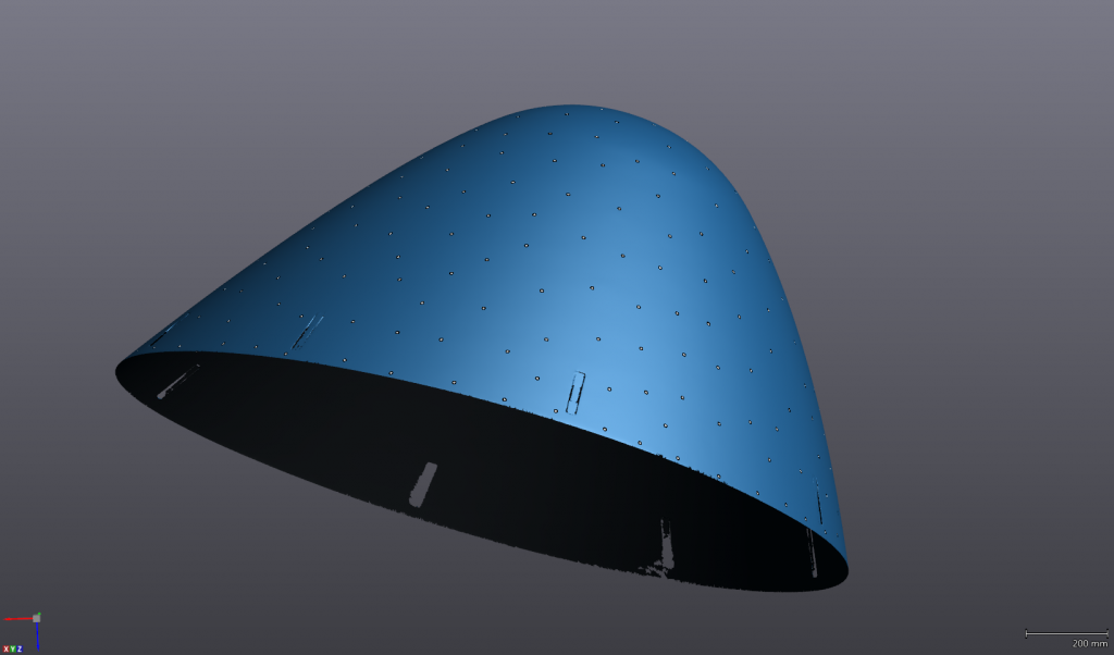
To repair the above-mentioned components, adhesive trays made of carbon or glass fiber are used. Shapes and contours must be checked regularly. The production process takes place under the influence of pressure and temperature variations in an autoclave, so that the material can expand. The extent of the expansion is determined by periodic scans. It is not a one-off project—but a regular measure to ensure quality standards.
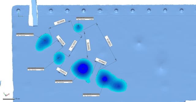
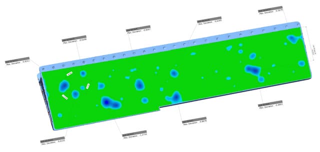
Screenshots of a scanned aircraft nose
The actual state is checked with Creaform’s HandySCAN 3D scanner or, for large objects, with the photogrammetry camera MaxSHOT 3D and compared with a CAD model (target state). On the software side, the data acquisition software, VXelements, is used for data acquisition. On top of providing reliable measurements, Creaform systems are used for other applications, such as reverse engineering, with the help of VXmodel scan-to-CAD software module.
Decision Criteria and ROI
Before LHT started using Creaform systems, measurements, data processing and reverse engineering were provided by a third-party company. The quality of the data as well as the duration of implementation and flexibility in changing conditions led to the decision to purchase hardware and software, thereby building the company’s internal know-how.
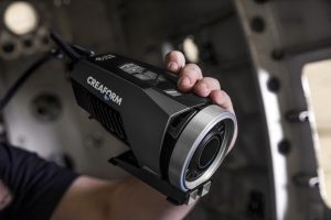
Decisive for the choice of the measuring systems were the compactness of the devices as well as the simple data acquisition with the HandySCAN 3D scanner. With these key features, it is possible to capture complex geometries with relatively little effort. In addition, the accuracy for the intended applications is sufficiently high. The MaxSHOT 3D helps to ensure unprecedented accuracy even for larger objects. Currently, the measurement systems are used exclusively in a workshop environment under (mostly) controlled, climatic conditions.
Photogrammetry camera MaxSHOT 3D measures large objects with high accuracy
“The control of the material expansion could have been measured with other common measuring systems, but the price-performance ratio and the compactness of the 3D measuring systems from Creaform made the decision easy. In addition, the customer service is impeccable,” explained Gunnar Hinrichs, who works at the Airframe Related Components Department at LHT. “In terms of ROI, the purchase has also paid off, even if we do not yet have any meaningful data. But it is likely, according to our own estimate, to have a give-figure amount in the lower segment, which we save on outsourcing. If we detect quality deviations at an early stage by using the Creaform technology, we can prevent unnecessary costs and therefore expensive reworking at the customers’ sites.”
Compact, Simple and Flexible
The experience with the Creaform systems is positive. “We can respond much faster and more flexibly to measurement tasks, discuss the measurement results directly at the measured component, and share information with other stakeholders. The systems consistently convince us we made the right decision with their compactness and simplicity of use. A measurement process, including pre- and post-processing (assembly, attachment of the targets, etc.), is completed within 2-3 hours. The data is available in real time. The software interface is well-implemented, understandable and clear. The training provided by Creaform is outstanding and the employees are always available for advice and support. That’s the way you want it to be,” said Hinrichs.
Product: Opcenter Industry: Electronics and Semiconductors
The Opcenter APS solution implementation significantly increased our efficiency by minimizing activities that did not bring value.
Ivan Koussarov, Division Manager, Sheet Metal AQ Electric Radomir
Meeting demanding requirements
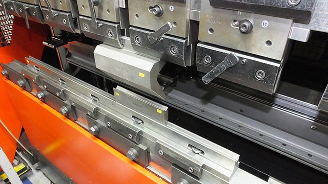
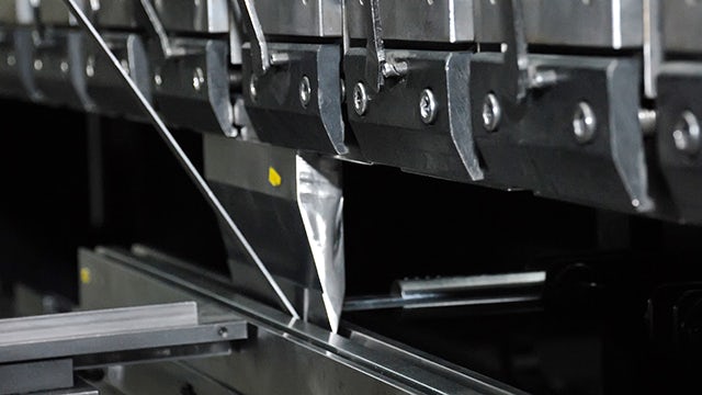
AQ Electric Radomir (AQ Electric) is a part of AQ Group AB (Sweden), which is a manufacturer of electrical cabinets, metal structures, electrical panels and components for global industrial customers with demanding requirements. The company has expertise in the design, production and delivery of a wide range of low voltage (LV) and medium voltage (MV) electrical cabinets as well as equipment for automation, sheet metal products and crane cabinets. The production processes also include cables and cable harnesses as well as mechanical assembly of components. AQ Electric products are used by industries such as power transmission, telecommunication, trains, food and trucks. The company has at its disposal a machine workshop with personnel that has more than 50 years of experience, two painting lines, a welding workshop for ferrous and nonferrous metals and machines for cutting, bending and stamping of sheet metal products.
Further, there are workshops for assembling and testing of electrical panels up to 20 kilovolt (kV) according to the International Electro-technical Commission (IEC) 61439 and for production of cable products as well as a line for cataphoresis coating. AQ Electric has a design team for metal and mechanical construction and design of electrical panels. AQ Electric has an annual turnover of €34.6 million, 750 employees and a factory with a production area of 22,000 square meters.
Challenges
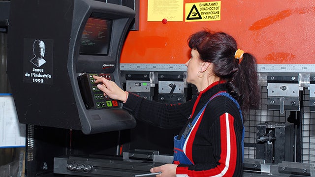
The production is organized in two segments: sheet metal components and electrical cabinets assembly. Planning is key due to the complexity and variability of the produced parts. The management team is focused on production optimization, cost efficiency and integrating new technologies to provide the best product quality. They knew they needed a specialized software solution to satisfy these needs.
Claes Meligren, the AQ Group chief executive officer (CEO), says, “AQ aims to be a world leader in cost effectiveness, quality, security of supply, alertness and service. In a word, ’reliable.’”
The main challenges are the complexity of the production processes and the products manufactured, the huge number of production orders, the availability of a lot of primary resources and additional constraints such as instruments, equipment and operators. The great number of resources and constraints interfered with the ability to generate an effective production schedule.
Many AQ Electric users were engaged to generate production schedules by department and synchronizing these micro plans was a serious challenge. The appearance of each unplanned event such as a breakdown or late material delivery ruined the production schedule and required significant time for recovery.
The supply chain department did not receive proper information on what materials were needed and when, thus leading to overstock.
The solution
All these pains led to the decision to implement an advanced planning and scheduling (APS) solution. The aim was to eliminate waste (scrap, poor quality, over production, unneeded areas, stock, extra transports, etc.) to increase profitability and show environmental concerns as well as increase production efficiency.
After a detailed analysis of the solutions available on the market and assisted by SmartApps Ltd – a Siemens Silver partner with expertise in advanced planning and scheduling – AQ Electric selected Opcenter™ APS software Ultimate Edition as the best option to fit their needs. Opcenter APS is part of the Xcelerator™ portfolio, the comprehensive and integrated portfolio of software and services from Siemens Digital Industries Software.
SmartApps is accredited as a Siemens Smart Expert for the Opcenter APS portfolio. It has developed integration modules for Opcenter Advanced Scheduling with many enterprise resource planning (ERP), manufacturing execution system (MES) and supervisory control and data acquisition (SCADA) systems in a variety of industries.
The implementation
During the implementation, a detailed analysis of the production model and processes in the company was made and the main sources of waste were identified. A strategy for achieving a balanced optimization was developed. Optimization algorithms, specific for each department, were developed, keeping in mind the specific requirements and additional constraints. An overall rule for synchronized scheduling of all company departments was created. The SmartApps team also developed integration with the existing ERP system.
Results
Due to the Opcenter APS implementation, only one planner is now responsible for production scheduling. By using the optimization algorithms in each department, the efficiency and internal on time in full (OTIF) have increased.
The changeover times decreased by 15 percent while the internal OTIF for most departments increased by up to 98 percent.
The implementation of Opcenter APS led to better communication and collaboration between departments and improved work synchronization.
“The Opcenter APS solution implementation significantly increased our efficiency by minimizing activities that did not bring value,” says Ivan Koussarov, division manager, sheet metal, AQ Electric Radomir. “The system gives us a glance at the future and the ability to identify potential problems and apply preventive measures before their appearance in order to avoid or decrease the damages.”
The system gives us a glance at the future and the ability to identify potential problems and apply preventive measures before their appearance in order to avoid or decrease the damages.
Ivan Koussarov, Division Manager, Sheet Metal AQ Electric Radomir
Product: Artec Leo Industry: Industrial Machinery and Heavy Equipment
From a means of survival to an essential economic activity around the world, agriculture has continued to transform and develop throughout history. Over time, it has made incredible strides. Aided by the rapid development of technology, agricultural operations now function in a much safer, more efficient, and sophisticated way. Still, the question remains: do these developments adequately address the challenges of the global food system, and sustainability issues?
Agri Techni Concept, an innovative French company, has a good answer.
Bringing innovation to the field, literally (Photo courtesy of Agri Techni Concept)
Addressing the needs of local farmers
The food we bite into every day comes through a complex global web of farmers, food manufacturers, retailers, and technology providers. The latter’s impact is often a determining factor in making farming methods more refined and the whole system more sustainable. Agri Techni Concept, based in Sore, a small region in southwestern France, has contributed much to getting local farming practices/routines on the modern (and greener) track. Not only does the company create specialized equipment for agriculture and forestry, they also give a second life to agricultural machinery for harvesting root vegetables across France’s southwest.
A manufacturer that aims to exceed customers’ expectations, Agri Techni Concept has always kept an eye out for new technologies that might help them create more functional, efficient, and long-lasting equipment. With this in mind, the company turned to CADvision, a leading provider of advanced and integrated 3D solutions in France. With their unique expertise in CAD and additive manufacturing, CADvision has been a long-term Artec 3D partner, helping many businesses make surefire strategic investments.
And while agriculture may not be the first industry that leaps to mind when considering the various applications of 3D scanning, the company’s scanner of choice – Artec Leo – is there to show what benefits one can reap when using it in exactly this sector.
3D scanning agricultural machinery with Artec Leo (Photo courtesy of Agri Techni Concept)
A unique 3D device to optimize harvesting
Benjamin Leroux, founder of Agri Techni Concept, has always been one for innovation. And for a special project, he needed a special solution: the company accepted the challenge of adapting and repairing agricultural equipment that would otherwise face obsolescence. To help farmers use tried and tested machines while still improving harvests by integrating customized parts, Leroux opted for Artec Leo, the world’s first and most renowned wireless 3D scanner. For Leroux, the three main criteria that helped him make his choice were Leo’s limitless portability, autonomy, and strong capacity for high-quality data acquisition.
This one-of-a-kind tetherless device makes 3D scanning completely effortless. In fact, the whole scanning process is so intuitive and easy that you may be overwhelmed with the power it holds within (just to give you a hint – a new NVIDIA processor, 5” HD built-in display, and battery). Leo guarantees accuracy and high-quality data capture at every stage of the process, which is crucial for older machinery parts drawings for that are no longer available.
Adaptability and precision that count
What made the entire project more challenging were the particular requirements of the farmers. For example, sand carrots, the vegetable Agri Techni harvests from light soils, need to be thoroughly cleaned right in the field, to facilitate further processing in the factories. Since only specific machines would be suitable for this, Leroux and his team needed to adapt the equipment to make it more efficient.
“Artec 3D technology gave another meaning to my work, I was able to gain speed but also precision to offer more qualitative models.”
To create an integrated carrot-cleaning module, Agri Techni first met with a customer to examine the machine intended to accommodate this module. The team designed an item in the form of a rubber star system to get carrots through, in order to remove as much sand as possible, thereby cleaning them. To make sure this core module would be fully integrated into the machine, they digitized the equipment with Leo.
Customized carrot cleaning module (Photo courtesy of Agri Techni Concept)
Farming in 3D – faster, sharper, easier
Scanning was mostly done in two to three minutes, in some cases extending to ten minutes in case the object was bigger than usual. Once scanned, the data from the objects was sent to Artec Studio for quick processing and tidying. Famous for high-precision results, the intuitive 3D software allowed to seamlessly complete the scanning process and export the 3D model into CAD software for further specific manipulations. “When the data is sent to Artec Studio, I work on the file to ensure that the rendering will be perfectly cleaned of the various imperfections noted during the scan,” Leroux explained.
“The scanner allows me above all to obtain precise measurements to have a substantial database that will be easily usable for processing in CAD software. 3D technology gave another meaning to my work, I was able to gain speed but also precision to offer more qualitative models.”
Any machine adaptations fit perfectly thanks to 3D digitization (Photo courtesy of Agri Techni Concept)
Another example was of a customer who was keen to cut his sowing time with the help of a modified equipment. Agri Techni specialists came to the farm to inspect the machine and discuss possible options – then, they came up with a plan to install a fertilizer spreader and mount a hoe on a lifting system to minimize the number of passes for the tractor.
The machine was scanned in minute detail to make sure any adaptations would perfectly fit its shape. “Agricultural machines are often quite bulky, so it was necessary for me to have a practical and easily transportable scanner to carry out my operations directly at the farmers without any logistical constraints,” Leroux said of the process.
Agri Techni has participated in a range of equipment adaptation projects, all of which required precision and adaptability only 3D scanning technology could offer. Whether when scanning large parts or taking precise measurements off the hard-to-reach ones, Artec Leo easily took care of the difficult parts. To provide farmers with the machines they needed, Leroux needed to adjust parts to properties and dimensions of many different objects, which would also be impossible without accurate 3D digitization.
Highly precise parts reproduction made possible (Photo courtesy of Agri Techni Concept)
According to the French company, there was no blueprint available for most agricultural machines they had encountered in similar projects. Some essential yet timed machinery units would thus be especially challenging to recreate, as would the ones of the curved, irregular shape, such as soil-loosening machinery buckets. Artec Leo came to the rescue: it was now entirely possible to measure such parts with submillimeter precision so that the replacements fit perfectly on the machines. Even without repair or restoration plans in place for older machines, the team would be able to reproduce spare parts for them quickly and easily. Instead of excessive consumption and additional investment, farmers would get the chance to enhance the equipment they already had.
A global perspective: agriculture transformed
Regardless of their complexity, agricultural machinery parts now have a chance for a second life. In a global vision, this means that the use of 3D technology does not just optimize the equipment customization for the farmers, but enables them to save time, funds, and effort in the long run, leading to greater sustainability. Knowing this fully well, Agri Techni Concept are currently planning to extend their practices and offer 3D scanning services directly to companies who are looking to streamline their agricultural workflows.
There’s a lot on the horizon for the agricultural sector, because the history of innovation keeps unfolding. Replacing parts for machinery, manufacturing bespoke tools, scale models for farming facilities – these are just a few of the cost-effective solutions 3D scanning could offer. With 3D methods and tech evolving massively, some of the most pressing farming challenges may be solved with these advancements – like they have been this time, in the fields of France.
Product: Solid Edge Industry: Industrial Machinery and Heavy Equipment
Using Solid Edge XaaS, we can efficiently check and modify product designs before we enter the manufacturing stage, which significantly reduces overall process time.
Lee Chang-woo, CEO Robogates
Developing robotics and AI technology solutions
Robogates develops and supplies robotics and artificial intelligence (AI) technology solutions to customers in industries such as smart factories, smart farming and warehouse automation. Robogates has an AI Robot Technology Research Center to help designers study and develop robot and AI-related research. Robogates is expanding its operations not only in South Korea but also in foreign markets like Japan, China, Vietnam, Myanmar and India.
Combating increasing production costs
Since Robogates is a small and medium-sized business (SMB), it must develop and sell various robot products such as AI robots and collaborative robots in small quantities, often with short delivery times. Since one designer is in charge of a product project from concept to production design, the designer’s workload has become a big problem. The company was using a 2D computer-aided design (CAD) tool and the designer could not keep up with the work-flow demands. Robogates was looking for a solution to this problem and started using Solid Edge® XaaS software to streamline the product development process. Solid Edge XaaS is part of the Siemens Xcelerator portfolio, the comprehensive and integrated portfolio of software, hardware and services.
Since it was impossible to develop the product in three dimensions with the previous design tools they used, the company could not determine whether interference or parts could be assembled during actual production. Due to this, frequent design changes occurred, resulting in delayed product shipment and deteriorating quality. Robogates repeated these design changes until it could ship the goods as perfect products, resulting in major unexpected losses, such as increased costs and workload due to repetitive manufacturing.
Since product design errors were only discovered at the production stage, product shipments were often delayed. In the previous environment, there was no choice but to evaluate the quality based on the experience of skilled workers and the product results that were completed.
Since there was no link between assembly drawings, part drawings and various lists, workers had to manually update them all or ignore them altogether. Even if designers had the latest version of the blueprint, this resulted in low accuracy. Designers had to spend a lot of time and effort on design work, such as front view, plan view, side view, hidden lines, construction lines and dimensioning. This prevented designers from investing time in improving product quality and over-coming these problems. Robogates began to reassess this process with Jikyung Solutec, a Siemens Expert Partner.
Focusing on efficiency and productivity
Because a single designer is responsible for a product project from conceptual design to production design, the designer’s workload has always been a major issue. Robogates needed a 3D CAD solution that could be used to organically manage small quantities and varieties of product data during the entire process.
With Jikyung Solutec, Robogates first examined whether it could use Solid Edge XaaS to organically link 2D and 3D product data at each stage of development.
The Robogates team focused on how using Solid Edge XaaS could help them with design verification, design change, design time, efficiency and design data scalability. The designers anticipated that using Solid Edge XaaS would help them efficiently create 3D shapes, drawings, product properties, specifications and bill-of-materials (BOMs). They also hoped that they could use Solid Edge XaaS to remove design changes due to design errors and reduce unnecessary drawing work. They also expected to reduce the amount of ancillary work that could decrease product shipment time and significantly reduce related costs.
Robogates confirmed that using Solid Edge XaaS helped the team re-use existing 2D-based product data and modify products quickly with more freedom. Designers were also able to use innovative product design ideas by using synchronous technology. “Using Solid Edge XaaS, we can efficiently check and modify product designs before we enter the manufacturing stage, which significantly reduces overall process time,” says Lee Chang-woo, chief executive officer (CEO) for Robogates.
However, it was still difficult to introduce new solutions and change the existing process that employees were familiar with. To introduce this new software solution, each department went through lengthy discussions and implemented Solid Edge XaaS training for designers. The team also relied on success stories of similar companies and they highlighted many advantages of using Solid Edge XaaS. Using Solid Edge XaaS allowed designers to modify work faster and more easily, which ultimately sped up the design process tremendously.
Benefits at every stage of production
As a result, Robogates used Solid Edge XaaS to develop collaborative robots for smart factory implementation and robot products for customers in warehouse automation. The company has improved productivity by using multiple BOMs, including robot product simulation and 3D shape information. This helped the designers share product data using the new data flow system, that delivered accurate product information to product processing and and manufacturing processes and also improved the re-use rate of product data.
Using Solid Edge XaaS product data management helped make collaboration between departments more seamless. Now, when there is a request related to product analysis, designers use the Solid Edge XaaS simulation to obtain the product analysis result.
By using Solid Edge XaaS, the designers performed assembly and interference checks between parts and the simulated product operation prior to actual production, which eliminated many problems. Even when Robogates deployed multiple robots in a customer’s smart factory, they were able to easily check interference during operation in advance.
Previously, the team had to produce prototypes for each product to identify problems or performance in actual operation, which was time-consuming and costly. Using Solid Edge XaaS to perform interference checks between parts and product operation simulation led to a reduction in product design errors, which enabled more complex mechanism design as well as reduced overall product production costs by 15 percent compared to the previous environment.
By using Solid Edge XaaS and the BOM input and output function, they produced accurate workorders, which was useful in the production and parts purchasing process.
Additionally, Robogates used Solid Edge XaaS to create complete 3D models for each robot product. Now the team can easily produce a driving simulation and actual images of robot products and create customer presentations and product promotional materials to use for the sellers, which also helped increase sales.
“In the robot product development stage, it is now possible to use Solid Edge XaaS to easily and quickly identify interference problems during complex operations that were difficult to grasp at a glance in the past,” says Chang-woo. “We can use Solid Edge XaaS to correct problems immediately during the product design stage.”
In the robot product development stage, it is now possible to use Solid Edge XaaS to easily and quickly identify interference problems during complex operations that were difficult to grasp at a glance in the past. We can use Solid Edge XaaS to correct problems immediately during the product design stage.
Product: Figure 4 Industry: Automotive and Transportation
Speed is the name of the game in Formula One (F1) racing, both on the track and for everything behind the scenes. Using 3D Systems’ innovative eggshell molding solution, BWT Alpine F1 Team has gained the production speed, quality and flexibility it needs to innovate and accelerate development on silicone and polyurethane parts like never before.
“With the Figure 4 eggshell molding solution I’m seeing things every day that I’ve never seen before. I can’t think of another way we could make this many different components in this many silicone and PU materials at this relentless of a pace.”
– Pat Warner, Advanced Digital Manufacturing Manager, BWT Alpine F1 Team
RAPIDLY PRODUCE MOLDED ELASTOMERIC PARTS FOR WIND TUNNEL AND ON-CAR APPLICATIONS
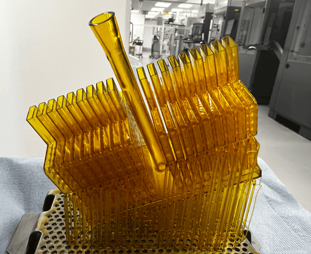
Example of a universal gasket used in wind tunnel testing, designed to print in a batch of 36 on the Figure 4 Modular.
Conventional tooling methods for molding silicone and polyurethane parts are time consuming, often excluding them from consideration for F1 development. With only a few months between racing seasons and a push for nonstop progress year-round, speed of production, testing and iteration is paramount. Given the grueling environment of the track and wind tunnel, there is no negotiating part performance either.
Shortening development and manufacturing time
3D Systems’ Figure 4 solution for eggshell molding enables BWT Alpine F1 Team to produce a diverse range of high-quality molded silicone and polyurethane parts in record speed, providing unprecedented access to one-off and iterative parts using conventional molding materials. The straightforward workflow keeps up with the aggressive pace of Formula One, making it a tremendous asset to the team. For example, casted grommets or seals that would take multiple days or weeks using conventional metal tooling or vacuum casting can now be delivered in a single day using Figure 4.
BWT Alpine F1 Team runs multiple builds a day on its Figure 4® Modular 3D printer for a wide range of casting tools for on-car parts and testing. Pat Warner, BWT Alpine F1 Team’s advanced digital manufacturing manager, estimates that most 3D printed eggshell molds print in just 90 minutes, with the largest builds taking up to three hours.
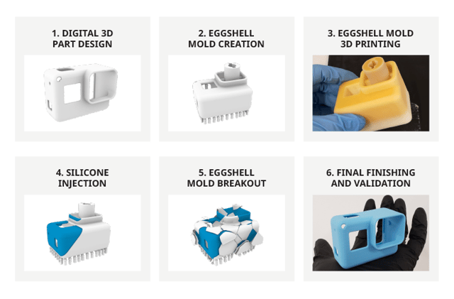
Eggshell molding is a sacrificial manufacturing technique that uses 3D printing to produce a thin, single-use mold that is injected with the final production material and then broken away.
Flexibility across multiple applications
The team’s productivity gains extend beyond same-day parts to the ability to address a wide range of applications using the Figure 4 eggshell molding process. The process relies on 3D Systems’ Figure 4® EGGSHELL-AMB 10 material, a process-optimized material for producing sacrificial tooling with the flexibility to deliver final parts in a range of silicones, polyurethanes and other materials such as metals and ceramics. Figure 4 EGGSHELL-AMB 10 is a rigid plastic specifically engineered to withstand injection at high temperature and pressure, but which breaks away easily after casting.
According to Warner, this flexibility has been a major benefit: “We have a huge array of materials, and we can basically use all of them in the period of a day.” This allows the team to look at a broad range of applications varying in stiffness, elongation, color and other properties. “I can’t think of another way we could make this many different components,” Warner said. Most applications currently addressed using 3D Systems’ eggshell molding solution fall into the categories of grommets, seals and gaskets, which are used throughout the car.
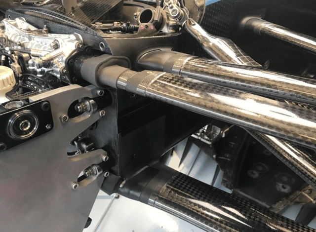
Suspension seal and frame for testing produced with polyurethane casting using Figure 4® EGGSHELL-AMB 10 and selective laser sintering in DuraForm® PA, respectively.
03 Straightforward workflow
The straightforward CAD to casting workflow begins with sending the file to print within 3D Sprint®, an all-in-one software for polymer 3D printing. The software’s extensive toolset includes options for adding supports as well as managing the printing process. Once printed, BWT Alpine F1 Team post-processes the casting shells, which involves cleaning the parts and post-curing them in the LC-3DPrint Box post-curing unit. This process takes roughly two hours and primarily consists of a 90-minute, hands-off post-cure.
After UV post-curing, BWT Alpine F1 Team coats the 3D printed casting shell in a chemical releasing agent and the shell is ready for polyurethane or silicone pouring. Cure times vary depending on the material used and can take anywhere from 10 minutes to 24 hours.
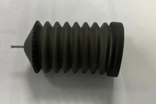
Silicone bellows like the above are being produced at BWT Alpine F1 Team for the car’s braking system.
04 Performance in a grueling environment
The performance demands on Formula One parts are extreme. Races take up to two hours, during which the entire vehicle is subjected to wildly varying temperatures, intense vibration and brutal forces. “It’s a horrible environment to put something you haven’t seen before yesterday,” said Warner, “and we are always striving for perfection. We must ensure that all our parts perform the tasks they are given.” The parts produced using 3D Systems’ eggshell molding solution meet this high threshold for performance. Warner says the surface quality is very good, which is especially important for aerodynamic parts. The ability to rapidly produce high quality, high performance parts also makes it possible for the team to now modify parts that were previously deprioritized due to the extreme time constraints of the sport.
Bottom line, the benefits of 3D technologies along with dedicated software are direct and substantial over conventional metrology. Components were positioned in hours, rather than days. Time savings on measurements, increased accuracy, removing user error and unmatched traceability, are just some of the benefits of state-of-the-art measurement technology.
MRO: How to Choose the Best 3D Measurement Solution?
To choose the right 3D measurement solution for your maintenance, repair and engineering project, start by mapping out your current 3D measurement or inspection process, and identify the major, most recurring problems of your workflow and opportunities for improvement.
Of course, accuracy, portability and price all make great impact on decision making, but the more information you can get about the target application and the results you want to generate, the better your choice will be.
Considerations with respect to object dimensions, environment, processing speed and software compatibility will help you find the solution that best fits your needs. That way you will probably be able to start simple and scale things up along the way.
For instance, decision-makers in the aerospace MRO industry will tend to orient their choice based on the fact that the objects to scan are relatively large, that the environment greatly affects the surfaces, and that time is of the essence: the longer aircraft are grounded, the more stakeholders lose money.
Do not hesitate to reach out to various providers to ask for a demonstration and discuss your current challenges with 3D measurement specialists. Creaform offers a full suite of 3D solutions for this type of work: metrology graded, truly portable, fast and versatile. We maintain an ISO 17025 accredited in-house calibration laboratory and can provide unmatched support across the world. Creaform offers traceable solutions that will provide you measurements you can rely on.
Product: HandySCAN Industry: Aerospace and Defense
US Department of Defense Uses 3D Measurement to Solve Maintenance Challenges
The United States military sector is faced with a host of technical challenges when it comes to maintenance, repair and engineering. Aircraft only have value if they are flight worthy. Personnel responsible for this need efficient and effective means to reduce risks, costs, and maintenance turnaround.
3D scanning instruments and technologies remedy discrepancies due to user errors, they allow for time-saving MRO and reverse engineering operations, and are effective for providing CAD files for 3D-printed replacement aircraft parts and prototypes.
Metrology Hardships in Military: What Can 3D Measurement Do to Help?
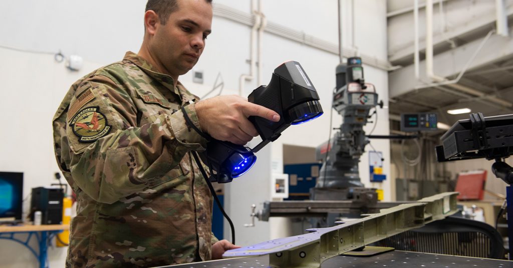
Tech. Sgt. Kevin Collins, 366th Maintenance Squadron aircraft metals technology section chief scans an aircraft structure at Mountain Home Air Force Base, Idaho, March 2, 2020. The HandySCAN 3D allows Airmen to scan a structure, eliminating the need to hand draw it on the computer. (U.S. Air Force photo by Airman Natalie Rubenak)
Heavy aircraft maintenance often means long-term grounding, resulting from errors in custom repairs.
Since reliable CAD data is typically not available, the aircraft must be measured to make repairs. Measurement discrepancies typically result from the lack of adequate tools to measure multiple objects and complex surfaces in addition to the challenges to inspect a wide range of part sizes, finishes and colors.
In a nutshell, 3D scanning devices and technologies can be used to accelerate reverse engineering, MRO operations and 3D printing applications, thus increasing mission effectiveness.
Reverse Engineering – Manual to Digital
MRO – Streamlining Inspection and Structure Damage Analysis
Align and Mate: The Bell Helicopter Case
Reverse engineering process: From manual to digital
The 366th Maintenance Squadron (MXS) at Mountain Home Air Force Base (MHAFB) acquired a Creaform HandySCAN 3D handheld 3D scanner to scan large aircraft structures quickly and efficiently.
Prior to using the device, MHAFB Airmen would use “facsimile mold” to fix broken parts or recreate structures. The main issue with facsimile mold is that it takes 48 hours to dry. “When it is done drying, you take it out and still have to go in and measure everything and hand draw it on the computer. It [is] so time consuming,” says Tech. Sgt. Kevin Collins, 366th MXS aircraft metals technology section chief. This tedious reverse engineering process consisting in manually designing models on the computer puts the personnel at the mercy of user errors and premature maintenance.
3D scanners provide the data required to perform full-scale engineering, manufacturing and development of parts and structures. 3D scanning for reverse engineering removes the user error factor and provides unmatched traceability for documentation purposes. Also, device portability means on-site analyses, and reduction of inspection times. 3D scanners are critical tools to support solid reverse engineering processes.
The model above was scanned using a HandySCAN BLACK portable 3D scanner; you can zoom in and see the level of detail around the edges, the holes, the bends and the fasteners. This complex, large part (680 mm X 320 mm X 60 mm) displays several features which would be difficult to measure without 3D scanning instruments.
Another problem faced by MHAFB Airmen is that of accuracy. The mold would often provide little to no accurate results, which would eventually lead to rework and wasted time. “With the scanner, we never run into that issue. In fact, it’s accurate up to about 0.025 mm,” Collins said.
Parts manufactured following this type of reverse engineering process can be quickly and accurately compared to CAD drawings to control 3D dimensional quality.
2. MRO – Streamlining Inspection and Structure Damage Analysis
Fairfield’s Travis AFB, via the 60th MXS, reported using various innovative strategies to improve mission effectiveness and reduce wasted time. The Air Force allocated $64 million in Squadron Innovation Funds to “increase readiness, reduce cost, save time and enhance the lethality of the force,” said Joshua Orr, 60th MXS. Among the new technologies were 3D printing and 3D scanning; the former using the latter to print and replace aircraft parts that suffered damage.
In one notorious case, a C-5 aircraft had been damaged by hail, resulting in numerous dents and scratches on all of the plane’s panels. Every 180 days, Travis Airmen would inspect the aircraft to locate and measure the dents that were still on the wing’s surface. Using traditional measurement tools and methods, performing this task would take around 48 hours. But equipped with a Creaform HandySCAN 3D and SmartDENT 3D, the Airmen were able to complete the inspection in 30 minutes. Unlike manual dent measurement methods, SmartDENT uses good material around damage to create reference surface and provide reliable measures.
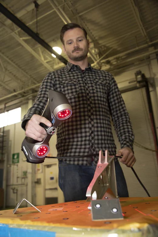
Joshua Orr, 60th MXS, uses a Creaform HandySCAN 700 to capture digital information to render a three-dimensional image of an aircraft part into specialized computer software.
“We had that C-5 in our hangar last week and we were able to inspect the four primary structural panels in 30 minutes.”
Master Sgt. Christopher Smithling 60th Maintenance Squadron assistant section chief for aircraft structural maintenance
Moreover, the procurement of two additive manufacturing units by the 60th MXS will undoubtedly unlock development, repair, replacement and production capabilities at Travis AFB. Aircraft are typically down for two days when a replacement part is needed. However, a solution comprising a 3D scanning device, scan-to-CAD technology and 3D printing can dramatically decrease out-of-service time. “With the two additive manufacturing units, we will be able to grab any aircraft part, scan it, and within four to eight hours, we will have a true 3D drawing of it that we can send to the additive manufacturing unit to print it,” said Christopher Smithling, 60th MXS.
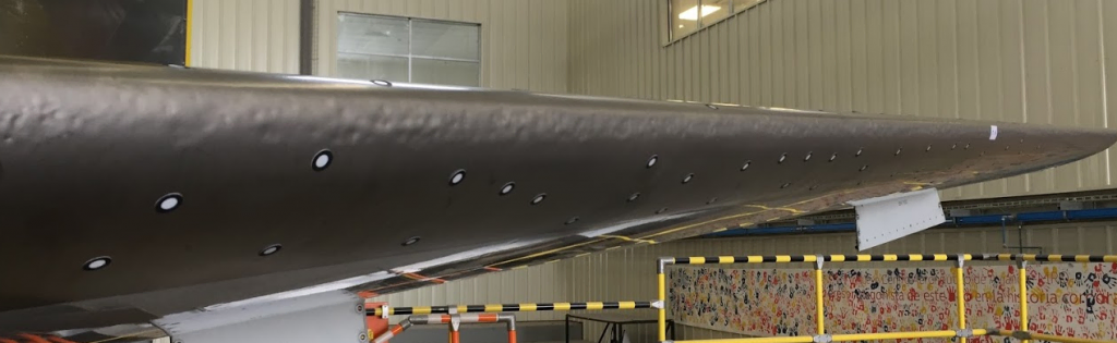
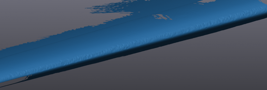
Back to the hail storm matter, Creaform developed a complete 3D scanning solution for the aerospace industry named HandySCAN AEROPACK. It addresses the specific challenges of aircraft quality control, such as assessing damage resulting from aircraft incidents and natural phenomena, like hail, as well as flap and spoiler inspections. The 3D scanner and software package includes VXinspect, VXmodel, SmartDENT 3D and provides the most versatile solution for a maintenance base/MRO facility.
Leading edge of stabilizer of a Boeing 767 damaged by hail3D scan of the leading edge of a Boeing 767 aircraft using a 3D scannerAnalysis of leading edge of a Boeing 767 stabilizer in SmartDENT 3D. Total analysis/reporting time is 30 minutes for full stabilizer damage assessment with a 25-micron accuracy compared to 1-2 days with traditional manual methods.Sample dent inspection on an aircraft. Feature measurements with out of tolerance maximum depth.
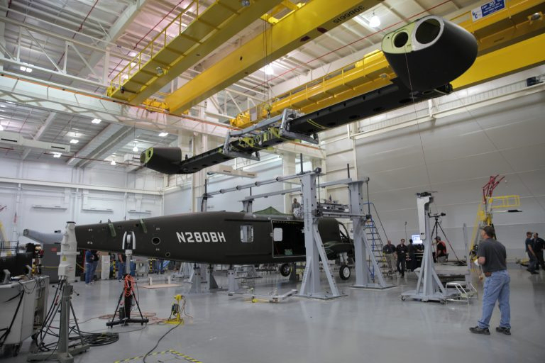
3. Align and Mate: The Bell Helicopter Case
At their Amarillo factory in Texas, Bell Helicopter, a Textron Inc. company, performed the mating of heavy components with the V-280 Valor’s fuselage, a medium-lift tiltrotor transport prototype aimed at “[rekindling] the Army’s interest in tiltrotors.” First, nacelles were attached to the wing, and then the nacelles-wing assembly was attached to the fuselage. These complex operations require vivid attention to detail, bearing in mind the extreme accuracy with which the massive components must be oriented and positioned prior to the mating process.
Multiple C-Tracks and the Creaform VXtrack software module for dynamically tracking multiple objects came in handy to accurately measure the position and orientation of the components of this assembly in real time, as they are assembled (in this case, the tiltrotor’s wing, nacelles and fuselage).
V-280 Valor wing mating at Bell Helicopter Amarillo. Photo courtesy of Bell Helicopter.
Bottom line, the benefits of 3D technologies along with dedicated software are direct and substantial over conventional metrology. Components were positioned in hours, rather than days. Time savings on measurements, increased accuracy, removing user error and unmatched traceability, are just some of the benefits of state-of-the-art measurement technology.
MRO: How to Choose the Best 3D Measurement Solution?
To choose the right 3D measurement solution for your maintenance, repair and engineering project, start by mapping out your current 3D measurement or inspection process, and identify the major, most recurring problems of your workflow and opportunities for improvement.
Of course, accuracy, portability and price all make great impact on decision making, but the more information you can get about the target application and the results you want to generate, the better your choice will be.
Considerations with respect to object dimensions, environment, processing speed and software compatibility will help you find the solution that best fits your needs. That way you will probably be able to start simple and scale things up along the way.
For instance, decision-makers in the aerospace MRO industry will tend to orient their choice based on the fact that the objects to scan are relatively large, that the environment greatly affects the surfaces, and that time is of the essence: the longer aircraft are grounded, the more stakeholders lose money.
Do not hesitate to reach out to various providers to ask for a demonstration and discuss your current challenges with 3D measurement specialists. Creaform offers a full suite of 3D solutions for this type of work: metrology graded, truly portable, fast and versatile. We maintain an ISO 17025 accredited in-house calibration laboratory and can provide unmatched support across the world. Creaform offers traceable solutions that will provide you measurements you can rely on.


-640x360.jpg?w=900&fit=max&q=60&dpr=1&auto=format)
-640x360.jpg?w=900&fit=max&q=60&dpr=1&auto=format)
-640x360.jpg?w=900&fit=max&q=60&dpr=1&auto=format)
-640x360.jpg?w=900&fit=max&q=60&dpr=1&auto=format)
-640x360.jpg?w=900&fit=max&q=60&dpr=1&auto=format)


 Photogrammetry camera MaxSHOT 3D measures large objects with high accuracy
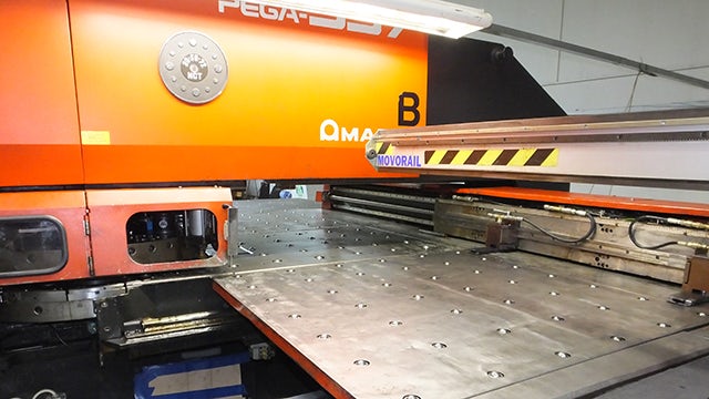


-640x360.jpg?w=900&fit=max&q=60&dpr=1&auto=format)
-640x360.jpg?w=900&fit=max&q=60&dpr=1&auto=format)
-640x360.jpg?w=900&fit=max&q=60&dpr=1&auto=format)