Product: Tecnomatix Industry: Automotive and Transportation
Tecnomatix provides a compensation alignment capability that can deliver accuracy as high as 98 percent in production line simulation, thus reducing the amount of rework on the shop floor.
He Wei, Production Director Guangzhou MINO Auto Equipment Co., Ltd.
Accelerated growth
Guangzhou MINO Auto Equipment Co., Ltd. (MINO) is the largest and leading high-end automotive equipment supplier in South China. Since its establishment in 2008, MINO has attained significant expertise and has become one of the best automation equipment enterprises in China’s auto industry, realizing an average annual sales growth of more than 200 percent.
Since its founding, MINO has experienced dramatic success, capital investment and expansion. Between 2010 and 2012, the company secured venture capital funding of more than 60 million renminbi (RMB). In 2013, the Chinese Ministry of Industry and Information Technology awarded MINO RMB 6.5 million in special support funds for the company’s flexible conveying system, and MINO’s industrial robotic integration system was awarded RMB 3 million in support funds from the Economic and Information Commission of Guangdong Province. In 2014, the company secured additional venture capital funding of RMB 120 million and began construction of a new facility in Huadu district.
Leveraging Tecnomatix for enhanced competitiveness
Since the automotive industry has extensively implemented mature automation applications, automakers expect the production lines in their facilities in China to be designed using 3D planning and simulation testing. Years ago, MINO adopted Robcad™ software in the Tecnomatix® portfolio for robotic simulation. MINO used Robcad, a solution from product lifecycle management specialist (PLM) Siemens Digital Industries Software, for mechanical simulation and offline robot programming in individual work cells, but the offline programs often required control engineers to debug the control systems on site to properly synchronize the robots and equipment. Using Robcad alone, the company was unable to meet the commissioning requirements of an entire complex production line with electronic controls.
After comprehensive evaluation of a broad range of criteria for design, simulation and analysis capabilities and technical support, MINO decided to adopt a comprehensive range of Tecnomatix solutions.
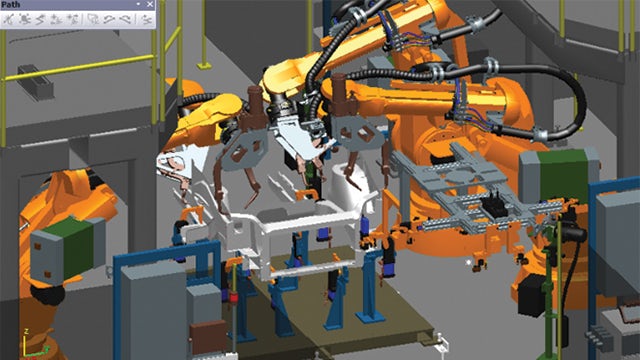
The Tecnomatix portfolio of digital manufacturing solutions provides design, analysis, simulation and optimization capabilities for plants, production lines and work cells, and delivers process innovation by linking all manufacturing disciplines with product engineering, including process layout planning and design, process simulation and validation and manufacturing execution.
The use of Tecnomatix helps MINO improve the quality and accuracy of production line designs. “By simulating the whole production line, we can identify defects and problems in the design to make necessary corrections before real production,” says He Wei, production director at MINO. “Tecnomatix provides a compensation alignment capability that can deliver accuracy as high as 98 percent in production line simulation, thus reducing the amount of rework on the shop floor.”
Navigating a complex project
For implementation of the Tecnomatix solution, MINO worked closely with Siemens Digital Industries Software solution partner Guangzhou Gohope Info-tech, which helped navigate the project and provided training services. Using the body-in-white (BIW) welding line for example, Guangzhou Gohope collaborated with MINO to develop independent welding process planning, design, simulation and virtual commissioning capabilities and conducted training on the software to improve the company’s efficiency and quality in body process planning. The collaboration helped shorten manufacturing preparation time on the body production line and improved the capacity of the company’s auto welding lines.
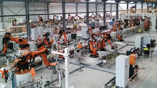
In 2015, with the help of technical teams from Guangzhou Gohope and Siemens Digital Industries Software, MINO successfully wrapped up the largest project of the year – phase three of the GAC passenger car welding project, which includes 63 KUKA robots with an 80 percent level of automation and an expected annual throughput of up to 180,000 units. It took 20 engineers just half a year to finish a range of advanced simulation tests using Tecnomatix. The accomplishment leads the industry in both project lead time and technology complexity, and was unimaginable before joining hands with Guangzhou Gohope.
“Besides the Tecnomatix solution, Guangzhou Gohope’s extensive practical experience in the automation industry, professional after-sales service and technical support teams, and a complete technical training system are among the main reasons that drove us to enter into long-term cooperation with them,” says Zhou Xiaowen, mechanical engineering manager at MINO.
By simulating the whole production line, we can identify defects and problems in the design to make necessary corrections before real production.
He Wei, Production Director Guangzhou MINO Auto Equipment Co., Ltd.
Yinxu National Archaeological Site Park (Photo: 163.com)
The Yinxu oracle bones
Oracle bone inscriptions are the earliest known systematic characters in China and East Asia, with a history of more than 3,000 years. The oracle bones were mainly unearthed in the area of Xiaotun Village, Anyang, Henan Province. Historically called Yin, Anyang was the capital of the late Shang Dynasty. Oracle bone inscriptions are usually engraved on tortoise shells or animal bones, and most of their content is related to divination by the Yin and Shang royal families.
Today, oracle bone research has become a subject of great interest around the world. At present, more than 150,000 oracle bones have been unearthed, about 2,500 characters have been identified, and about 2,000 characters have yet to be deciphered. There are more than 500 Chinese and foreign scholars engaged in oracle bone inscriptions, with more than 3,000 monographs and papers published. The study of oracle bones has also promoted the development of various disciplines such as linguistics, history, ethnology, astronomy, meteorology, agriculture, medicine, historical geography, and archaeology.
On Dec. 26, 2017, these oracle bones were successfully included in the UNESCO Memory of the World Register, a compendium of the world’s documentary heritage.
Chiselling an oracle bone (Courtesy of the CCTV documentary “the Dynasty of Oracle Bones”)
The ancient method of inscription rubbing
Since the discovery of oracle bone inscriptions by epigrapher Wang Yirong during the Guangxu period of the Qing Dynasty, oracle bone inscription researchers and enthusiasts have faced a challenge that is crucial to solve: how to transcribe, disseminate, and share the textual information on oracle bones without causing damage to the oracle bones themselves.
The mainstream traditional technique used in academia is the rubbing method, an ancient traditional technique used in China. Before the birth of modern technology, rubbing made it possible to preserve the original appearance and details of the object to the best possible extent. In addition, repeated rubbings obtain multiple identical rubbings, which is comparable to printing. The ability to make rubbings has been an essential skill for oracle researchers.
Making a rubbing (Courtesy of the CCTV documentary “the Dynasty of Oracle Bones”)
When making rubbings, you need to apply soaked paper material onto the oracle bones and tap lightly with a brush to push the paper down into the engravings. When the paper is slightly dry, ink is evenly applied. The paper is then peeled off to form a black and white rubbing.
Although rubbing is the most mainstream transcription technique in the academic world, it has many limitations. For example, the oracle bone must be touched while making rubbings, which might cause damage to the object. In addition, the results of the final rubbing are influenced by temperature and humidity conditions, as well as the operator’s skill level.
Introducing 3D scanning
Dr. Li Zongkun is a chair professor and PhD supervisor in Humanities at Peking University, which has a collection of over 4,000 oracle bones. Dr. Li, devoted to the research and teaching classes on oracle bones and palaeography, passes the skills of rubbing on to his students using his extensive first-hand experience. However, this technique is subject to some practical limitations and demands physical contact with the bones.
One day, he came across 3D technology and decided to take a closer look: to see how well it could apply to his work with oracle bones.
Peking University
To test his idea, Dr. Li asked a 3D scanning specialist from trusted Artec 3D reseller ASAHI-3D to scan an oracle bone in the university’s collection using Artec Space Spider. As Artec partners in China, ASAHI-3D has worked in close cooperation with Peking University and offered many 3D scanning solutions.
For scanning: an inscribed bone used for divination. (Photo: Peking University)
The object selected for scanning was an inscribed bone that was used for divination – 31.1 cm long and 16.1 cm wide, the bone is part of a long-treasured collection in the School of Archaeology and Literature of Peking University, dating back to the late Shang dynasty (more than 3,000 years ago).
There are 45 characters on the front, and one character that has almost disappeared on the back, epitomizing the oracle bone inscriptions of the Shang dynasty. This bone can also be pieced together with another small bone (Collection of Oracle Bones, No. 11574) now in the National Library. The two divination scripts on the bone are both related to war.
Dr. Li and a specialist from ASAHI-3D (Courtesy of the CCTV documentary “the Dynasty of Oracle Bones”)
ASAHI-3D chose Artec Space Spider to capture both sides of the oracle bone. Jiao Chunliang, Technical Director of ASAHI-3D, said, “Artec Space Spider is an amazing 3D scanner, which has played a key role in many scanning projects. Precise capture is possible even without any targets or preparation, making a lifelike digital replica well within reach. Zero contact ensures safety for cultural relics. From a cloisonné vase in the early Qing dynasty to Terracotta Warriors, reverse engineering small objects can be a walk in the park. Space Spider has made many brilliant models possible.”
Artec Space Spider scanning the oracle bone (Courtesy of the CCTV documentary “the Dynasty of Oracle Bones”)
An improved process
Space Spider can start capturing data in just one click, with no targets required. The specialist simply needs to point the scanner at the bone from a distance of 20-30 cm. While the scanner is moved around the bone, the captured 3D surface data is displayed on the computer screen in real time.
After the front of the bone is scanned, the bone is turned over and scanned using the same process; the scanning session takes only a few minutes from start to finish.
Artec Studio screenshot showing scanning of the oracle bone (Courtesy of the CCTV documentary “the Dynasty of Oracle Bones”)
The scan data is then processed in Artec Studio. After outlier removal, the front and back scans of the oracle bone are aligned, so as to make a complete model. Next, global registration and fusion algorithms are run to create a final mesh model.
The oracle bone has an extensive amount of surface detail, which can prove to be a challenge from a texture-reproduction perspective. However, the photorealistic texture feature in Artec Studio fully meets the requirements of the client, and without the need for any other software, the original color was replicated using hi-res textures captured using various photogrammetry equipment (e.g. DSLR cameras). The final result: a complete, lifelike model of the oracle bone that is fully suitable for research and a range of other applications.
A close-up of the color model
After processing the scans in Artec Studio, the 3D model can be exported to third-party software, such as Geomagic or ZBrush, for additional processing. Following the scanning process, the scanning specialist was able to present complete information on the oracle bone with the digital rubbing made from the scan data.
Using a different method of data capture from the past, a 3D-scanned digital rubbing of oracle bones no doubt offers an abundance of possibilities for digital archival and museum exhibitions.
A digital rubbing (left), compared to Artec Space Spider scan data
Working with Space Spider means no spray or targets are required for capturing oracle bones, which means zero risk for these priceless artifacts. The total scanning process takes only a few minutes, and Space Spider’s high-quality data and Artec Studio’s efficient algorithms together ensure a relatively small file size, which further reduces scan processing time. As a result, high-resolution color 3D models are produced quickly and easily.
Countless opportunities
Regarding the use of 3D scanning in heritage preservation, the client explained, “3D scanning technology is able to satisfy the rising demand for digitization of cultural relics. It has proven to be a reliable tool for archiving and restoring valuable heritage, and it has inspired new ideas and approaches. This is something innovative that we need to pay more attention to.”
Jiao Chunliang from ASAHI-3D added, “We are honored to be part of the oracle bone scanning process. This is a brand new way of recording history and is of much significance to heritage preservation and digital archiving. We hope that, in technical terms, the whole process is effective and the clients are pleased. As long as we have captured all the data, it may be possible to showcase the 3D models of oracle bones in a VR or AR environment, bringing cultural heritage within reach of students all over the country.”
Product: NX CAM Industry: Industrial Machinery and Heavy Equipment
I was pleased with our improvement in mold design efficiency. However, I thought we could do more to improve our overall efficiency. To achieve that, we had to unify our CAD and CAM environments.
Akira Kokubo, President Uyama
Striving to be competitive in the global market
Established in the historical district of Fushimi-ku of Kyoto, Japan, the Uyama Mold Factory (Uyama) has been in the mold production business since 1962. Uyama’s main focus is mold design and production. The company’s customer base covers a number of industries that require high-precision production, including small electronic appliances, automotive, semiconductor and medical equipment. Since the company’s founding, Uyama has been very aggressive in implementing the latest equipment and tools. As part of its business expansion, Uyama opened a new facility for parts production in 2002.
Despite the company’s strength and success, Uyama was facing a variety of challenges. First, the United States recession of 2007-2009 caused a decline in business. Second, foreign competitors increased production capacity, putting downward pressure on pricing. Third, customer requirements were getting more difficult to meet. In addition, the company faced the prospect of replacing a number of experienced engineers who were preparing to retire.
To overcome these challenges and increase sales, Uyama established three goals: develop a new customer base, improve the efficiency of its mold development processes and differentiate its services from those of competing companies.
“To achieve those goals, we undertook three tasks,” says Akira Kokubo, president of Uyama. “We automated production, cross-trained our engineers and increased sales capacity.”
Uyama knew it needed a top-notch 3D computer-aided design (CAD)/computer-aided manufacturing (CAM) system to reach these goals, so after a thorough evaluation of a number of solutions, Uyama chose NX™ software from Siemens Digital Industries Software.
Fully utilizing NX
Uyama simultaneously undertook the necessary tasks to accomplish its goals, especially the aggressive use of 3D. In recent years, most of the design data that came from customers was in the form of 3D CAD data, including 3D data changes from surface data to solid data, rather than 2D drawings. To have a smooth data exchange, Uyama needed to change its modeling environment as well.
Furthermore, it was difficult to perform conceptual design or mold base design in 2D and execute parting in 3D. Moreover, doing so was time-consuming and duplicated effort. Uyama needed to change the process to improve efficiency and determined everything had to be done in 3D. The management team found that the 3D system that best meets such mold design requirements is NX, with parametric design capabilities, a rich library and other important functionality that Uyama required. To achieve an efficient end-to-end mold design to machine path generation, Uyama implemented NX in 2002.
At the onset, Uyama designers mainly worked on mold parts. To significantly improve operational efficiency and achieve the company’s motto of “High precision, short delivery time, high added value” and, importantly, differentiate itself from its competitors, Uyama needed to more fully utilize the comprehensive functionality of NX.
To facilitate the successful launch of a fully engaged, 3D-based product development environment, Uyama decided to work with its partner, ISID, for implementation support. With ISID’s help, Uyama deployed an assembly design methodology, parametric mold design and customized parts library. Those efforts have made it possible to share an inventory of mold bases, and notably shortened delivery time to customers. Uyama also automated the creation of bills of materials (BOM) and order forms, significantly reducing human error and enabling greater production efficiency.
Now the entire process – from conceptual design to part order – is conducted in 3D and, as a result, the overall development time has decreased by 40 percent.
Unifying the 3D environment
“I was pleased with our improvement in mold design efficiency,” says Kokubo. “However, I thought we could do more to improve our overall efficiency. To achieve that, we had to unify our CAD and CAM environments. We wanted even more mold design efficiency and to do that, we needed to cross-train engineers.”
“On the production floor, we already had an environment to follow-up on each other,” adds Teppei Yoshikawa, head of engineering at Uyama. “However, between designers and CAM operators, because of system differences, they couldn’t support each other. The design engineers were using NX, but CAM operators were using a domestic CAM system. The barrier between the two systems was actually quite high.”
To completely streamline the process, it was necessary to have cross-trained engineers with knowledge of the entire mold design process. That led Uyama to seek to unify the system, to bridge design and manufacturing, which triggered an evaluation of NX for CAM use.
Uyama evaluated NX CAM for surface finish, machining time, and NC programming efficiency.
During the benchmark process it was clear that NX satisfied the machining quality and cycle time requirements. The existing domestic CAM system, developed with Japanese engineers in mind, had provided excellent surface finishing and a short turnaround. “After comparing the machined parts completed with NX to those completed with the existing domestic system, we found that the quality was the same,” says Yoshikawa. “Also, the actual machining time was virtually identical.”
The key advantage of NX CAM is its programming efficiency, which is superior to the existing CAM system.
The entire NC programming process has been streamlined and simplified. To quickly prepare the part model for CAM programming, engineers now use the design tools of NX. The advanced NC programming capabilities of the software enable Uyama to create highly accurate toolpaths with a minimum number of supporting elements. Yoshikawa notes, “Using NX, the company has reduced the number of NC programs necessary to machine parts, thus optimizing the manufacturing process. In addition, the computational time needed to generate the programs has been significantly shortened. By leveraging the capabilities of NX CAM, we have reduced the NC programming time of a typical part by 30 percent.”
Increased sales
Yoshikawa points out that, by using NX to establish the company’s entire mold production process, Uyama has achieved a smooth data exchange process with customers, achieved consistent high-quality design deliverables and markedly improved its collaboration with customers. As a result, Uyama has increased its business volume; in fact, the new design environment with NX has helped Uyama realize its increased sales goals.
Using NX, the company has reduced the number of NC programs necessary to machine parts, thus optimizing the manufacturing process. In addition, the computational time needed to generate the programs has been significantly shortened. By leveraging the capabilities of NX CAM, we have reduced the NC programming time of a typical part by 30 percent.
Product: Frigure 4 Industry: Electronics and Semiconductors
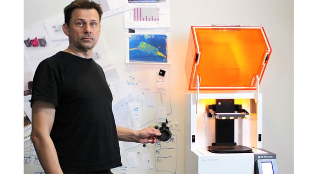
The Stockholm-based product design agency, Splitvision Design, is among the first Nordic companies to invest in 3D Systems’ Figure 4® Standalone 3D printer. With its investment, the company can now evaluate fitting and assembly with incredible accuracy before moving in to serial production. At the same time, the Figure 4 Standalone gives the company a productivity boost in prototyping.
Splitvision, a Nordic industrial design agency, adopts Figure 4 3D printing
Since its inception some 30 years ago, Splitvision Design (then named Formbolaget), has done a wide variety of design work – from point-of-sale solutions to bespoke truck cabs. Today, it works almost exclusively with industrial design for technology-intensive companies in the medtech and automotive verticals. The thing that makes Splitvision unique is that it offers services that stretch beyond the average design agency – with a focus on manufacturing and logistics.
“Even though we set out as a traditional design agency, over the years, we’ve seen that we get a better and more controllable manufacturing process when we focus on these steps,” says Lukass Legzdins, R&D manager at Splitvision Design.
“We went from just working with design, up to engineering, planning, purchasing and logistics,” adds Legzdins. We also have offices in China that handle the day-to-day contact with manufacturing over there. Here, we also perform quality control and monitor the supply chain. All in all, this creates really good results, and enables us to add a lot more value to manufacturing even at the concept phase.”
Better prototyping with Figure 4 3D printing
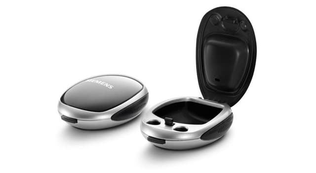
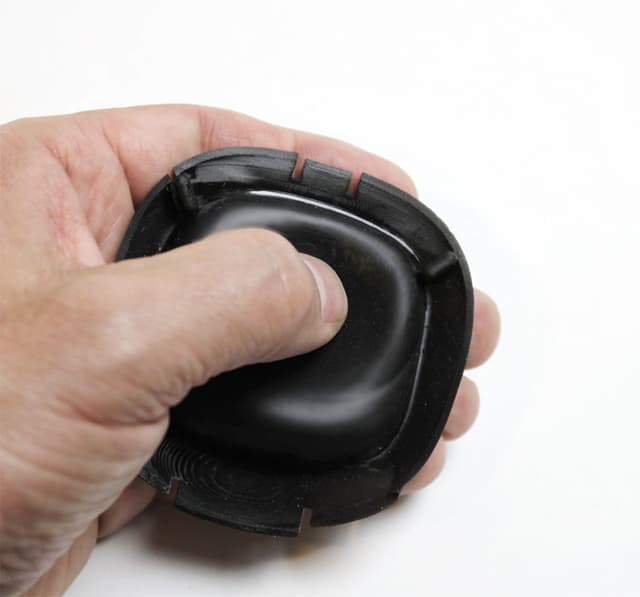
Product designs include cases for delicate electronics such as hearing aids
This type of turnkey commitment is also reflected in prototyping. With its new Figure 4 Standalone 3D printer from 3D Systems, installed by PLM Group, the company is expanding its services portfolio and adds competence to product development. Now, Splitvision can offer better physical prototypes, printed inhouse. At the same time, with the help of its high-quality 3D printed parts, they can optimize the data needed before ordering injection molding tools.
Before using 3D printing, prototyping was tedious and manual work. The company worked with materials in foam and plastics to explore geometries and ergonomics, sometimes in full scale. Prototypes for functional tests or for customer review were bought from a third party supplier, either from Sweden or China.
“Then, all of a sudden, there was this period when we had a massive amount of products under development, and everything basically piled up as we waited around for our 3D printed prototypes,” said Legzdins. “That’s the moment we decided to invest in an inhouse 3D printer, and luckily, it coincided with us discovering the Figure 4.”
Splitvision had no prior experience with Figure 4 technology, which is an offshoot of SLA, stereolithography. It had previously gone under the radar, as SLA parts rarely displayed the mechanical properties the company needed. But with the Figure 4, the technology suddenly became very interesting.
Additive Beyond Expectations
Splitvision has worked for several years with a number of innovative medtech companies, including several hearing aid brands. The production often consists of associated products, such as hearing aid casings, as the companies have optimized their production lines for their core products. But hearing aid casings can be tricky to design and manufacture. They need to protect the hearing aid, be of excellent quality and reflect the brand, and be durable over time.
“3D Systems’ Figure 4 ELAST-BLK 10 material has the same properties as rubber. It’s beyond our expectations,” says Lukass Legzdins, R&D manager, Splitvision.
The casings that Splitvision design and manufacture are partly made of TPE or silicone. The soft lining keeps the hearing aids in place and protects them from everyday wear and tear. But 3D printing TPE and silicone is next to impossible if you want good results. The only option is to mold, which is a big challenge when you want to evaluate design and investigate potential assembly challenges.
“After receiving a number of print samples from PLM Group, we realized that 3D Systems’ Figure 4 ELAST-BLK 10 material had the same properties as rubber. It was beyond our expectations,” Legzdins. “The material enables well-defined surfaces. We can see detailed shapes and facets. But most importantly, it allows us to evaluate the assembly process to identify potential challenges. Overall, it’s an excellent way for us to get confirmation of the geometry, while at the same time enabling our customers to do their own user tests.”
Combined with using the rigid Figure 4 TOUGH-GRY 15 material, Splitvision can add more detail to their parts. With the high resolution of the printer, there’s rarely any need for finishing.
“One could say that our Figure 4 takes us one step closer to reality,”said Legzdins. “Previously, we added more margin to our CAD files before ordering tools. Now, we can skip one or two steps in the development phase, as we have much more geometrical data from the 3D printed prototypes. The result is fewer incremental changes and adjustments to the tool.”
The Figure 4 printer also reflects Splitvision’s core values in product development.
“When we work with customers, we want to add our competence in design and manufacturing, wherever we see that we can optimize function. We use this knowledge to raise the quality of the product to new levels,”said Legzdins.
Product: HandySCAN Industry: Aerospace and Defense
EADS (European Aeronautic Defense and Space company) is a worldwide leader in aerospace, defense, and associated services. The company has been using Creaform portable 3D measurement products for several years.
More specifically, EADS uses both the HandySCAN 3D and the MetraSCAN 3D optical CMM scanner for scanning tooling and composite parts (carbon/epoxy) and for making parts/CAD comparisons. For its probing needs, EADS uses the HandyPROBE optical CMM. In addition to using VXelements, the data acquisition software behind all Creaform systems, EADS additionally uses the VXtrack module for dynamic measurements, as well as VXlocate, a software module developed through a partnership between Creaform and EADS.
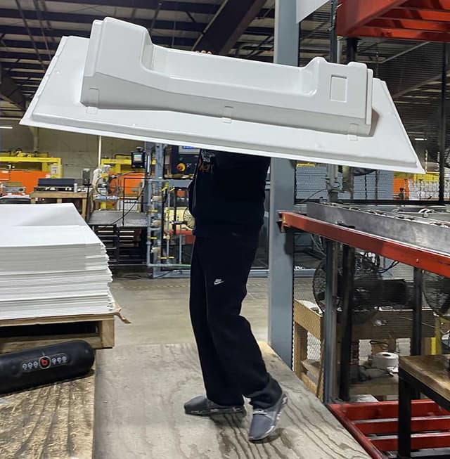
HandySCAN 3D Application Example
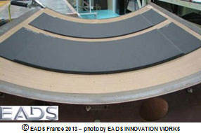
As part of a study on the possible geometric distortion of carbon fiber composite parts and with the help of a HandySCAN 3D device, EADS scanned a 1 000 mm x 800 mm tooling equipment, as well as 650 mm x 300 mm parts, to assess post-manufacturing deformation.
Parts on tooling
First, EADS scanned the tooling, in order to verify its compliance with the CAD plan.
Scanning the tooling with the HandySCAN 3D
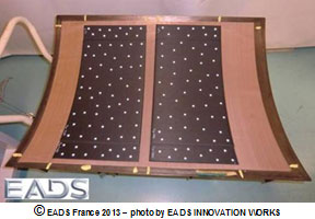
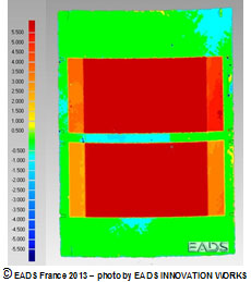
Then, two parts manufactured with this tooling were scanned, and the scanning files were compared.
Scanning the parts and results
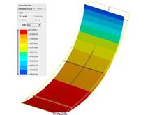
Results: tooling/parts gap
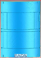
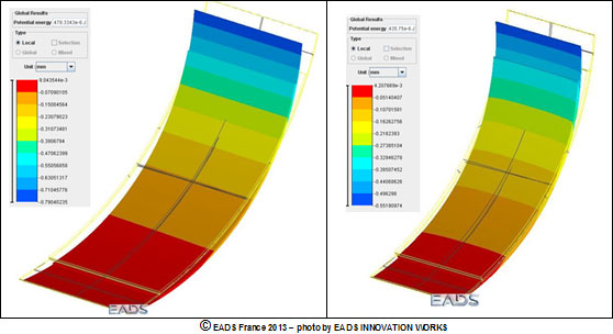
The second step consists of using very powerful simulation tools to estimate the distortion of the parts before manufacturing, in order to compare the manufacturing parts scanning files.
Simulation
The results EADS obtained made it possible to validate the simulation software, which was developed to optimize the manufacturing range by identifying adequate parameters and processes.
This project could have been completed with a fringe projection scanning system, but the one EADS owns cannot be used for such large surfaces, and the process is a lot more complex when it comes to measuring the two faces of the composite parts. Additionally, a CMM could have been used, but this possibility came with two drawbacks: one-off measurements, which in turn lead to a much longer acquisition time.
“ The Creaform system enabled us to quickly scan the metallic tooling and the carbon fiber composite parts. Many other systems that are available on the market do not work very well on these composite parts, which aspect is very dark and sometimes very glossy. The equipment being so portable made it possible for us to record the measurements right at the manufacturing site,” explained Ms. Catherine Bosquet, from the EADS Structure Health Engineering (NDT & SHM) department.
“ Before using Creaform’s systems, we used fringe projection, since we purchased a HOLO3 system over 15 years ago. We also tested other available systems (Konica Minolta, Metris, Steinbichler, Aicon, Kreon Technologies, Ettemeyer, GOM), but the Creaform 3D measurement solutions convinced us, because of their quick set up and acquisition, ease of use, measurement performance for many types of surface states, as well as their portability.We must also mention that Creaform experts are always highly available and responsive.”
We set out to build our digital factories of the future. This initiative was not about technology. It was about transforming the way we did business.
Kalyan Balsubramanian, Vice President and Chief Information Officer
Terumo charts its course to factories of the future
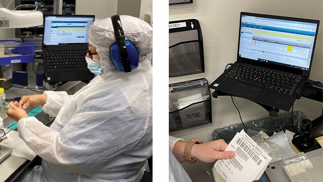
2021 marks the 100th anniversary of Terumo, a global leader in medical technology based in Tokyo, Japan. Terumo Americas is its largest business, growing to huge product lines across four divisions over the last 50 years, including interventional systems, injection and infusion therapy devices and drug delivery devices. These are life-supporting and sustaining Class 3 medical devices. Headquartered in Somerset, New Jersey, its production sites span North and South America.
Ten years ago, Terumo Americas implemented its first manufacturing execution system (MES), Camstar Medical Device Suite, in its Ashland, Massachusetts cardiovascular division. The goals were to streamline the quality and manufacturing processes and make the product release process more efficient. Delivering significant improvements in productivity, as well as reductions in NCRs and complaints of 40 to 60 percent, Terumo expanded the implementation to their Elkton, Maryland facility.
In 2018, Terumo Americas began a larger digital transformation initiative that included its business logistics layer and its manufacturing operations management (MOM) layer. With SAP S/4HANA selected as its enterprise resource planning (ERP) system, Terumo Americas leadership selected Siemens as its strategic partner for MOM, implementing Siemens Opcenter Execution, which was an evolution of the Camstar solution. These would be the major enterprise systems for their digital factories.
“We set out to build our digital factories of the future,” said Kalyan Balsubramanian, vice president and chief information officer of Terumo Americas. “This initiative was not about technology. It was about transforming the way we did business.”
The business challenge
Terumo Americas is the fastest growing region of Terumo. The management team of Terumo Americas was very clear on its intent to transform manufacturing to the smart factories of the future, not just implement new applications. The goal was to integrate its business logistics layer (ERP) with its manufacturing operations layer (MOM) and connect with automation and sensors – ultimately building the framework for Industry 4.0.
At the same time, Terumo needed to scale its production not only of quality products, but quality processes. The complexity of compliance requirements, especially with the U.S. Food and Drug Administration (FDA), was daunting. The company was laden with paper, with stacks five inches tall to review for the release of every material batch. This review process was taking days and delaying release schedules.
In addition, Terumo recognized that their product nonconformances were almost exclusively related to errors in compliance documentation, not the product. The products were perfect, but the paperwork was subject to human error, data entry mistakes and the like. Terumo sought to streamline the quality and production process to create efficiencies, while at the same time reducing their nonconformances.
The solution
Terumo Americas leadership invested significant resources in charting their path forward. They chose SAP S/4HANA as their ERP standard, and Siemens Opcenter™ Execution for Medical Devices as their MOM solution. Opcenter is part of the Xcelerator™ portfolio of integrated solutions and services from Siemens Digital Industries Software.
“We knew we had to have best-in-class people, best-in-class software, and best-in-class partners,” said Balsubramanian. “The secret path to achieving success was to build the knowledge base in house. The partners we selected were those that would work with us to create this end result.”
The Siemens advantage
Siemens had many advantages identified by Terumo Americas’ leadership team. They noted Siemens’ experience in the medical device industry, its relationship with the FDA, and its knowledge of best practices in computer systems validation. Siemens also offered a proven integration with the SAP system and had successfully implemented manufacturing execution systems (MES) at Terumo BCT/Cardio. In addition, Siemens also had cultivated a strategic partnership and cohesive relationships at executive and operational levels.
Terumo implemented Siemens Opcenter in its facility in Puerto Rico, scheduled to go live on the same day as the SAP solution. The company achieved what they considered the pinnacle of MES goals, the generation of eDHRs. The systems simultaneously went live at their largest site in Elkton, Maryland.
Given the size of the Elkton site, the team used a phased approach, implementing Siemens Opcenter by value stream. They also integrated Siemens Opcenter with their dark warehousing application. “Both implementations were extremely successful,” said Rick Larrieu, vice president of global IT applications and infrastructure at Terumo Americas. “We leveraged the Siemens expertise to help us build the roadmap and the implementation plan. We learned a lot from that experience, which will help us adapt for future deployments, as well as our integration with automation equipment.”
Benefits
“The transition to eDHRs has been of the utmost importance,” said Larrieu. “Before, we had to review a stack of papers five inches thick for the release of every material batch, which took a full day or more. With Opcenter, we are able to release batches in under 30 minutes.”
The paperless manufacturing environment delivered by Opcenter was transformational for productivity, as well as for streamlining quality processes. Terumo found that its previous product nonconformances had been caused by paperwork and data entry errors. As the MES controlled each of the data entry points, the company was able to reduce nonconformances dramatically.
Digitalization had positive impacts on the culture of the manufacturing organization. “This was not a technology initiative,” said Balsubramanian. “This was more of a people and process initiative. Unlike other enterprise system implementations, an MES is integral to the workflow of supervisors and operators. We had to bring these teams in from the very beginning to design a system that would be efficient and well adopted.”
“As we walked the shop floor, we encountered some unexpected challenges with data entry in our clean rooms,” continued Balsubramanian. “We found that we had to accommodate the physical conditions on the shop floor, including operators in clean room suits. The Siemens team helped us adjust for these types of environments.” The Siemens team also helped the internal Terumo team resolve issues in integrating with its material handling system.
The solution was designed and built to accommodate the way supervisors and operators would interact with it on a daily basis. With the amount of information to be entered, the solution had to be intuitive and efficient so that productivity would not be impacted. The out-of-the-box capabilities, along with few configurations, allowed them to present a solution that the operations as well as the shift supervisors were comfortable with. The flexibility and ease-of-use of Opcenter was noted as a huge benefit in this area.
Plans for the future
Terumo Americas is bringing the Industry 4.0 framework into their factories. The roadmap includes four levels of transformation. At the business logistics layer, Terumo plans to have a single instance of SAP for all entities in the Americas. At the MOM layer, the company is standardizing on Opcenter as a single platform for all factories in the Americas. At the automation layer, Terumo plans to integrate both the business logistics layer and the MOM layer with the production control layer, including equipment and sensors. The company ultimately will realize their vision of the digital twin, with the physical factory represented completely in the digital realm.
“Strategically, we have chosen the Siemens Opcenter platform to enable our smart factories for all entities in Terumo Americas,” said Balsubramanian. “Production control and production engineering systems are where we are headed, and we are thankful for our strategic relationship with Siemens. They will continue to help us go down this road.”
The Siemens Xcelerator portfolio enables life sciences companies to develop digital twins of product, production, and performance in the field. The approach of an open, flexible ecosystem allows the connection of enterprise systems, like SAP, to complete the digital manufacturing infrastructure. The resulting digital thread connects multiple factories, locations, operations and functions with a single, cohesive thread that creates quality and operational efficiency. This digital transformation is helping companies with innovation efficiency, regulatory compliance, and faster growth.
We leveraged the Siemens expertise to help us build the roadmap and the implementation plan. We learned a lot from that experience, which will help us adapt for future deployments, as well as our integration with automation equipment.
Rick Larrieu, Vice President of Global IT Applications and Infrastructure
Product: Artec Leo Industry: Automotive and Transportation
Background
From the time he was five, Chad Forward knew he wanted to build things. After 15 years of working in leading automotive design studios in Australia and design consulting for custom automotive shops, he started his own restoration business, Scratch Build Co, to continue doing what he always loved – building cars.
Launched in 2012 as a side project that Forward devoted himself to on weekends, Scratch Build is now a full-time design studio and collaborative space. There, Forward and his fellow subcontractors – automotive designers, technicians, and electricians – work on creating design solutions for aftermarket creators of automotive products or custom-built cars.
“I was always attracted to people who are excited about what they try to create,” said Forward. “By observing incredible craftspeople and amazing designers in Toyota, Ford, and other design studios, I really saw the opportunity to employ those people and build a space where everyone can come and create something for the benefit of the Australian auto market.”
As the name suggests, a lot of what Forward is doing entails building things from scratch, be it a part that can’t be bought anymore, or an entire process that a client is trying to reinvent. Until 2017, his typical reverse engineering workflow would take a great deal of time, without the results to show for it. “Sometimes it would take me a whole day to measure up a chassis, getting really basic measurements, and then trying to model from that information in CAD”, added Forward. “Often, because of taking everything on so quickly, I missed something that was fairly critical. And it involved going back and forth a number of times as well.”
“Artec’s cutting-edge and truly portable Leo scanner is a massive breakthrough in the 3D scanning industry.”
When Artec released its wireless handheld 3D scanner Artec Leo that year, Forward was immediately on board. “20 years ago when I had my first custom-car business, I thought this technology would never exist in my lifetime,” he said. Forward pre-ordered the scanner through Artec’s Australian reseller, Objective3D, and, according to the team, was the first lucky customer to get it at that time.
“Artec’s cutting-edge and truly portable Leo scanner is a massive breakthrough in the 3D scanning industry, and we at Objective3D are proud to bring this technology to the Australian and New Zealand market,” said Matt Minio, Managing Director of Objective3D. “It’s especially beneficial for automotive engineers who can use it to reverse engineer parts and see how they affect the performance of a vehicle.”
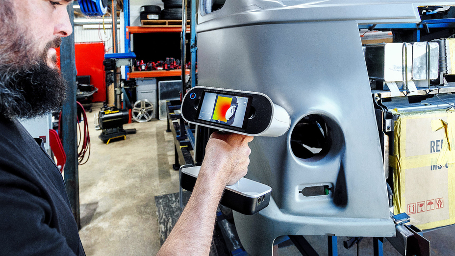
Artec Leo enables the founder of Scratch Build to measure any part simply (Image by streetmachine.com.au)
Designed with both mobility and ease of use in mind, Artec Leo is a powerful and one-of-a-kind 3D scanner that doesn’t need a PC or laptop to work with. An extensive field of view allows the scanner to easily snap both medium to large industrial parts, or entire vehicles in 3D, with quality-assured accuracy and exceptional resolution.
Powered by automatic onboard processing, wireless connectivity, inbuilt touch screen, and battery, the scanner provides full autonomy and freedom of movement wherever the user is, be it a custom car shop, a factory floor, or a far remote location with no power access.
For Forward, it was a no-brainer: “It took me four years to convince myself I needed to spend $4,000 on a 3D printer, but it took me 15 minutes to convince myself to buy a $40K scanner.”
Getting to work
Once the scanner arrived, Forward put it straight into work, and hasn’t stopped since: anything that needs to be measured car-wise now gets scanned with Leo, onsite in the shop or out in the field, saving him and his clients precious time. He now spends those free hours on CAD modeling, designing, and prototyping car parts and components, using the data he scans as a reference.
“The freedom that this single machine has offered me is unbelievable. Regardless of the location or parts’ complexity, I’m now able to capture the data simply,” Forward added.
Forward uses data from Leo as a reference for CAD modeling in SOLIDWORKS and Autodesk Alias (Image by streetmachine.com.au)
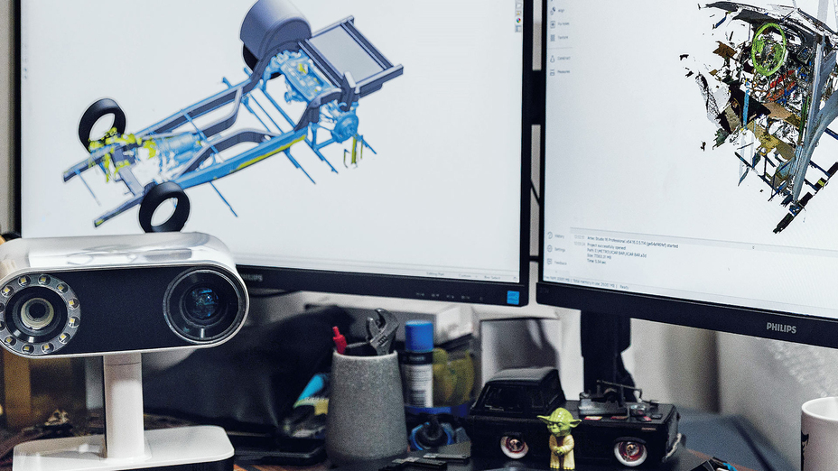
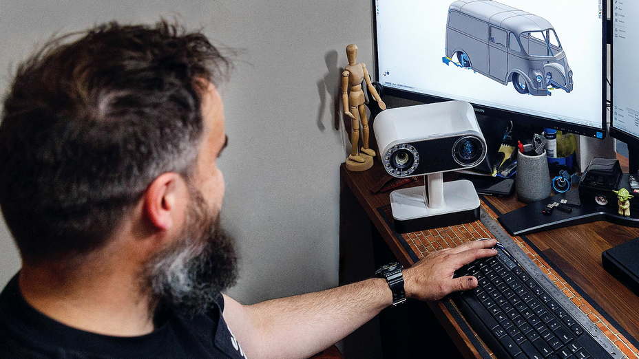
The typical workflow looks like this: Forward or one of his design colleagues drives to the client and scans whatever needs to be scanned, then all the data gets transferred to one of their desktop computers, which is set up solely for processing in Artec Studio.
“I have two desktop computers: one for processing all the scanned data and the second one for the CAD modeling. I always have things going on, so I prefer to run them in parallel,” Forward explained. Depending on the part scanned, he then loads it into either SOLIDWORKS or Autodesk Alias to create a solid CAD model.
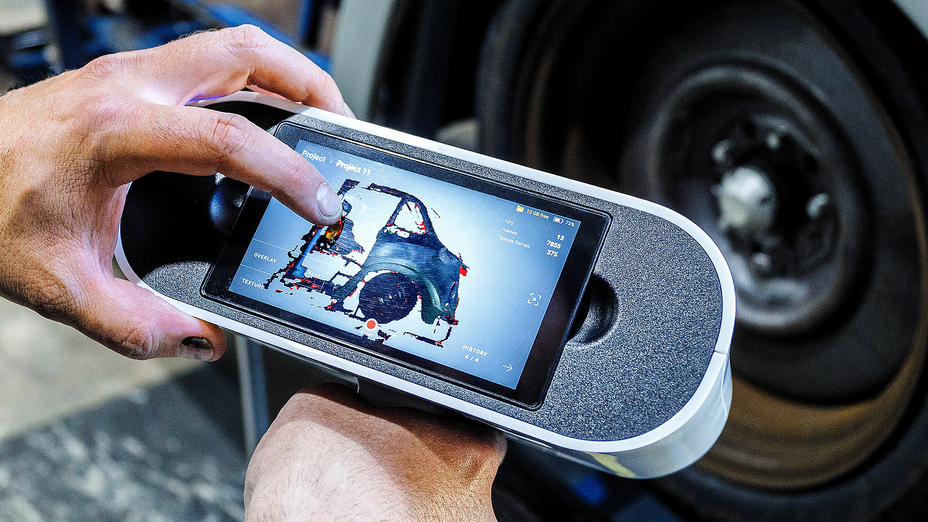
Artec Leo’s built-in display allows Forward to preview the results of his scan in real-time (Image by streetmachine.com.au)
Using a 3D scanner at the clients’ locations has also brought Forward new opportunities work-wise: “Every time I take Leo out somewhere, I am almost guaranteed to pick up another job from just visiting one place. One place will send me to another place, and so on,” he shared. While on site, he also collects more data than he needs to – building his own catalog of sorts, gathering valuable data from parts that can no longer be found.
The 1957’s International Metro Van
One of the biggest projects where Forward has been able to make full use of the scanner so far is the 1957 International Metro Step Van that he and his business partner from another automotive shop, Luke Williams, are on a mission to restore from the ground up by the end of 2023.
The owner of the van didn’t just want to renovate the vehicle as is, but pair its vintage exterior with the power of a sports car, featuring the supercharged 6.2L HEMI Hellcat V8 engine.
Coming standard on the Dodge Challenger SRT® Hellcat models, today’s most powerful modern American muscle cars, the V8 boasts more than 700 horsepower, which, unlike the van’s original engine, will allow the owner to freely drive his van all across the country. Apart from the engine, he also wanted to tune up the design, so the van looked less “puffy,” as well as retain all the factory electronics.
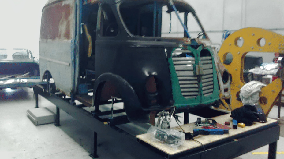
Original body of the 1957 Metro Van before the restoration (Image by Chad Forward)
After collecting the design and engineering requirements from the owner and making some preliminary sketches, Forward and Williams came up with a plan: since the van’s body was too worn out and rusty to restore, it would be faster to build the entire vehicle completely from scratch, using the scans of the older and modified parts as a base for modeling new parts in CAD.
Step 1. Sculpting the body
The first step: to cut up and sculpt the body. The plan was to modify an existing body – or one of its parts – to the desired shape, then 3D scan this part and use the data as a starting point for modeling an entire body in CAD.
In order to do that, Williams cut up a factory body with an angle grinder, welded it back in slightly different positions, and then used a lot of body filler and primer to create a matte surface that he was happy with.
The plan was to modify one of the body parts to the desired shape, and then 3D scan this part for modeling an entire body in CAD (Image by streetmachine.com.au)
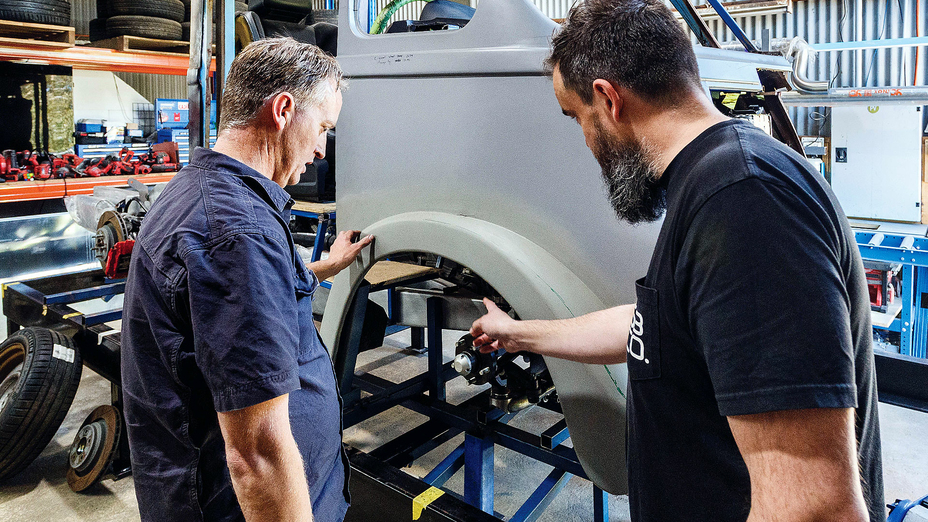
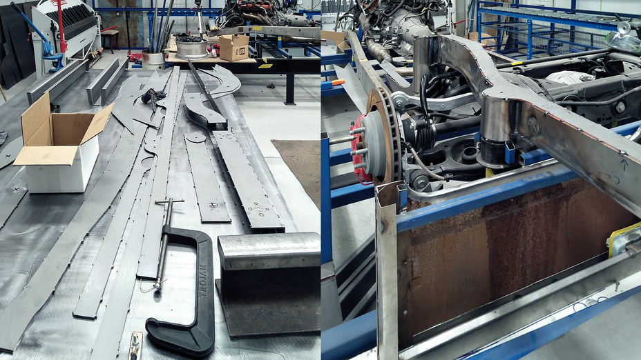
Step 2. Building the chassis
In the meantime, Forward set up all the drivetrain components of the Dodge Hellcat – the engine, all the wiring, the front and rear suspension – on a base platform that he built around the chassis. He wanted to see how all the components fit together, if they met ADR (Australian Design Rules) standards, and scan them to see which new chassis parts needed to be modeled in CAD.
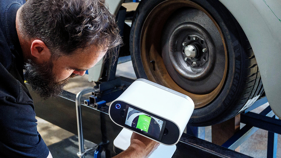
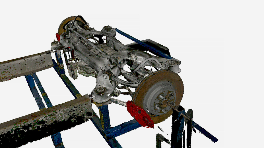
Step 3. 3D scanning
Then it was time for Forward to scan the primed front left corner of the van, as well as the chassis and other internal components, using his Artec Leo. All the scanning just took a few minutes; he then uploaded all the data to Artec Studio for processing and creating an .STL file.
Forward scanning the van with Artec Leo (Image by streetmachine.com.au)
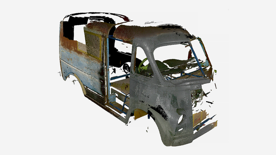
3D scan of a modified body, captured with Artec Leo
3D scan of a rear suspension
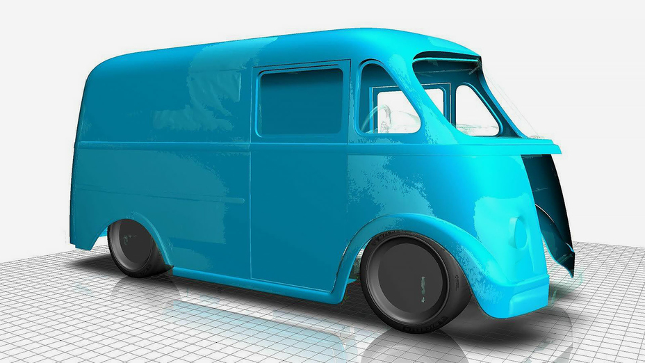
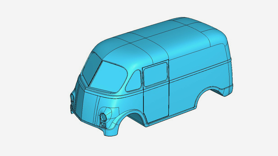
Step 4. Modeling the van’s body
Next: To model the body surface. For that, Forward imported the scan data from Artec Studio into Autodesk Alias, computer-aided industrial design software for automotive exteriors, and used this data as the blueprint to create the sketches of a future body surface.
Forward uses Autodesk Alias software to create car body surfaces from the sketches that he makes over the top of the scanned data (Image by streetmachine.com.au)
3D scan (light blue) and CAD data (blue) in Alias software
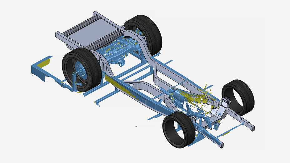
Step 5. Modeling the chassis
For modeling the chassis and all the other engineering parts, Forward uses SOLIDWORKS. Following the same workflow, he uploaded the scan data captured with Leo into SW and modeled the new parts around it. Having accurate 3D replicas of the internal components allows Forward to use them as precise references during his design process, and also have a clearer understanding of what issues he may run into. As he progresses through his design, he scans more components, and adds them to the software as reference models.
Forward uses the scan of the chassis to be modeled as a platform to create a CAD model in SOLIDWORKS
Step 6. Laser cutting & welding the new components
After the SOLIDWORKS stage, Forward sent all the CAD components for laser cutting, and then welding to the chassis.
Laser-cut flat parts loosely tapped together before final welding to the chassis (Image by streetmachine.com.au)
After welding all the chassis components, the whole internal build was sent to an auto electrician to get the chassis up and running with all the Hellcat’s original components. As this was taking place, Forward was preparing to cut up the body surface modeled from the scan data (in Step 4) to build an auto body buck that could then be used for fabricating the panels and test fitting.
The final design of the new body style that Forward will use to create the body buck
The team expects to finish all the body work in the next 12 months, having given themselves another few months to work on the interior, painting, and other smaller tasks by the end of 2023. Once complete, Forward hopes this project will become a good platform to educate other studios and clients.
“Metro Van is a great example of how I think all cars should be recreated,” said Forward. “Although our process takes time, it will take way longer to restore the old car as is, than to build it from scratch backed by the data from a 3D scanner. Being able to capture information in 3D, reverse engineer and make components based around what I’ve captured – that is what I fundamentally set up this business for.”
“As soon as HD Mode was available, it absolutely blew my mind – it’s like I bought a new scanner.”
Since Forward has switched to 3D scanning, he has never looked back. Being able to create exact digital copies of automotive parts instead of measuring them by hand has been a massive game-changer in the way he works, the accuracy of the data he collects, and his overall productivity.
And it’s only getting better. “I have always been amazed with the workflow and the continued upgrade of everything that Artec has done to stay ahead of the curve,” he said. “Every time the product re-opens, it’s like a whole new level of excitement for me. The difference between Artec Studio 15 and 16 is absolutely massive – as soon as HD Mode was available, it absolutely blew my mind, it’s like I bought a new scanner.”
Product: Figure 4 Industry: Automotive and Transportation
Duo Form, a leader in thermoforming for a wide variety of industries, advances its production capabilities with polymer pellet-extrusion additive manufacturing (AM). By collaborating with 3D Systems to integrate AM into its manufacturing processes and leveraging its Titan 3D printer, Duo Form is drastically decreasing costs, shortening lead times, and becoming more agile by 3D printing representative samples, production molds, and tools for thermoforming and vacuum forming processes.
“We have gained a lot of business with our Titan 3D printer. The turnaround time for parts, molds, and formed parts has put us leaps and bounds above our competition.”
– David Rheinheimer, Duo Form Product Development Manager
Time, Cost, and Delays in the Production Process
In the competitive thermoformed plastics market, Duo Form continually works to innovate its manufacturing process, shorten lead times and reduce costs to better serve its customers and win new business. At the same time, maintaining mold quality and durability is key.
Time and cost savings are not the only challenges, thermoformers like Duo Form face. They also need to innovate quickly with design iteration and produce full-scale prototypes to avoid delays in the approval and production process.
Producing Molds with AM
Duo Form now 3D prints thermoforming molds using polymer pellet-extrusion on its Titan 3D printer, replacing traditional CNC methods to create ceramic or metal molds. Large-format pellet-extrusion AM uses cost-effective thermoplastic pellets that are common to other extrusion manufacturing such as injection molding, and which cost up to 10X less than traditional FDM filaments. 3D Systems’ pellet extrusion systems also enable high-throughput printing, with print speeds up to 10X faster than filament systems.
3D Systems and Duo Form identified a grade of glass-filled polycarbonate pellets as an ideal material for printing thermoform molds, as it is affordable, easily procured, and has proven to withstand the thermoforming process as a durable and dimensionally accurate material.
Duo Form also leverages 3D Systems’ printing experience to achieve optimal printing parameters to print molds with the right porosity to function as vacuum passages. This unique ability of additively manufactured molds eliminates the need for special tools to properly form cavities into the thermoformed component, further reducing time and labor costs for producing molds.
Innovation and Design Iteration with AM
Incorporating AM goes beyond the mold-making process for Duo Form. As a leading innovator in its industry, Duo Form also utilizes its Titan 3D printer to quickly print sample parts of final products to present to customers ahead of making the tool. Directly printing parts for design approval before proceeding to the mold-making process has opened the door for faster design iteration and overall shorter lead times.
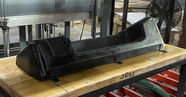
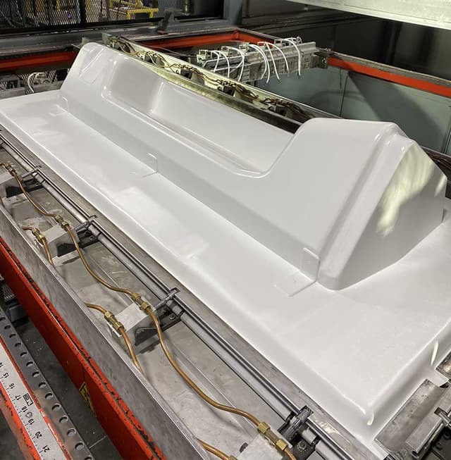
Significant Cost Savings and Reduction in Lead Times
Duo Form saw immediate results with the first thermoform mold the company printed on its Titan pellet-based 3D printer, a shower pan for a recreation vehicle. 3D printing the small shower pan reduced costs by more than 50 percent and printing took less than 20 hours, resulting in a high-quality mold with similar longevity to traditionally manufactured molds. Duo Form Product Development Manager David Rheinheimer reported that this 3D printed mold went into production and has been pulled over 1,000 shots without showing any significant wear and is still producing 100% quality parts.
Duo Form and 3D Systems also partnered on a project to produce a train interior panel using the Titan pellet extrusion system to demonstrate AM for large-format mold production. 3D printing this 1,294 mm x 410 mm x 287 mm mold shows the potential for up to 88 percent estimated cost reduction and up to 65 percent reduction in lead time compared to traditional ceramic mold methods and even greater savings when compared to traditional aluminum mold methods.
Since implementing AM as part of its manufacturing process, Duo Form says the company has won more business and now closes deals faster thanks to the speed and agility of pellet-extrusion 3D printing. As an example, Rheinheimer shared how Duo Form 3D printed a sample part to present to a customer along with a quote for forming the part. The customer, impressed with the speed and ability to see the final design first, awarded Duo Form the bid that same day. This is now standard practice for Duo Form and brings added value to its customers.
Rheinheimer says he can also see another value AM brings to manufacturers when it comes to storing molds, especially for products that are out of production but may need to be formed in the future for spare parts. With AM, a digital inventory means you can eliminate the need to store legacy molds, and instead quickly print a new mold whenever the need arises.
Additive manufacturing complements conventional production processes. Duo Form’s adoption of large-format pellet extrusion 3D printing exemplifies how AM and traditional methods can work together to achieve optimal manufacturing speed, cost management, and quality part production.


-640x360.jpg?w=900&fit=max&q=60&dpr=1&auto=format)
-640x360.jpg?w=900&fit=max&q=60&dpr=1&auto=format)
-640x360.jpg?w=900&fit=max&q=60&dpr=1&auto=format)
-640x360.jpg?w=900&fit=max&q=60&dpr=1&auto=format)
-640x360.jpg?w=900&fit=max&q=60&dpr=1&auto=format)


