

Product: Figure 4
Industry: Automotive and Transportation
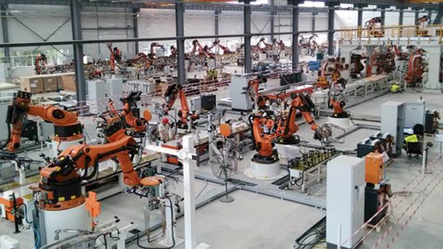
Speed is the name of the game in Formula One (F1) racing, both on the track and for everything behind the scenes. Using 3D Systems’ innovative eggshell molding solution, BWT Alpine F1 Team has gained the production speed, quality and flexibility it needs to innovate and accelerate development on silicone and polyurethane parts like never before.
“With the Figure 4 eggshell molding solution I’m seeing things every day that I’ve never seen before. I can’t think of another way we could make this many different components in this many silicone and PU materials at this relentless of a pace.”
– Pat Warner, Advanced Digital Manufacturing Manager, BWT Alpine F1 Team
RAPIDLY PRODUCE MOLDED ELASTOMERIC PARTS FOR WIND TUNNEL AND ON-CAR APPLICATIONS
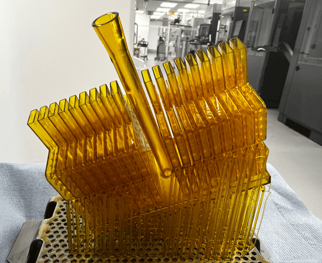
Example of a universal gasket used in wind tunnel testing, designed to print in a batch of 36 on the Figure 4 Modular.
Conventional tooling methods for molding silicone and polyurethane parts are time consuming, often excluding them from consideration for F1 development. With only a few months between racing seasons and a push for nonstop progress year-round, speed of production, testing and iteration is paramount. Given the grueling environment of the track and wind tunnel, there is no negotiating part performance either.
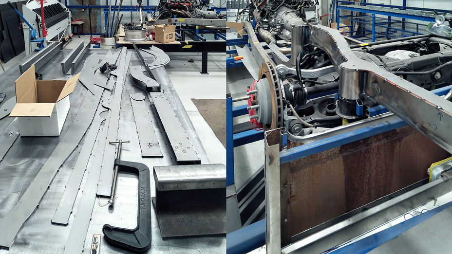
Shortening development and manufacturing time
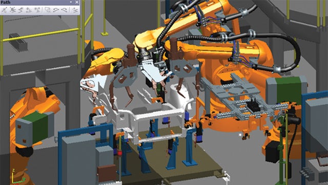
3D Systems’ Figure 4 solution for eggshell molding enables BWT Alpine F1 Team to produce a diverse range of high-quality molded silicone and polyurethane parts in record speed, providing unprecedented access to one-off and iterative parts using conventional molding materials. The straightforward workflow keeps up with the aggressive pace of Formula One, making it a tremendous asset to the team. For example, casted grommets or seals that would take multiple days or weeks using conventional metal tooling or vacuum casting can now be delivered in a single day using Figure 4.
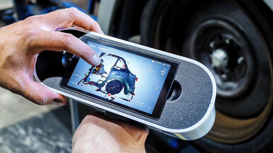
BWT Alpine F1 Team runs multiple builds a day on its Figure 4® Modular 3D printer for a wide range of casting tools for on-car parts and testing. Pat Warner, BWT Alpine F1 Team’s advanced digital manufacturing manager, estimates that most 3D printed eggshell molds print in just 90 minutes, with the largest builds taking up to three hours.
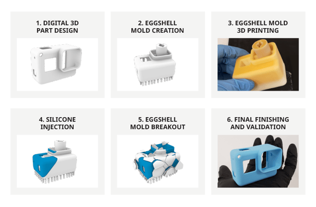
Eggshell molding is a sacrificial manufacturing technique that uses 3D printing to produce a thin, single-use mold that is injected with the final production material and then broken away.
Flexibility across multiple applications
The team’s productivity gains extend beyond same-day parts to the ability to address a wide range of applications using the Figure 4 eggshell molding process. The process relies on 3D Systems’ Figure 4® EGGSHELL-AMB 10 material, a process-optimized material for producing sacrificial tooling with the flexibility to deliver final parts in a range of silicones, polyurethanes and other materials such as metals and ceramics. Figure 4 EGGSHELL-AMB 10 is a rigid plastic specifically engineered to withstand injection at high temperature and pressure, but which breaks away easily after casting.
According to Warner, this flexibility has been a major benefit: “We have a huge array of materials, and we can basically use all of them in the period of a day.” This allows the team to look at a broad range of applications varying in stiffness, elongation, color and other properties. “I can’t think of another way we could make this many different components,” Warner said. Most applications currently addressed using 3D Systems’ eggshell molding solution fall into the categories of grommets, seals and gaskets, which are used throughout the car.
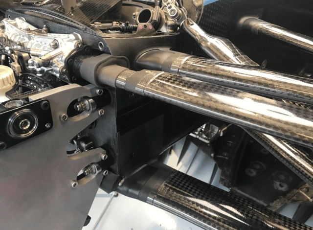
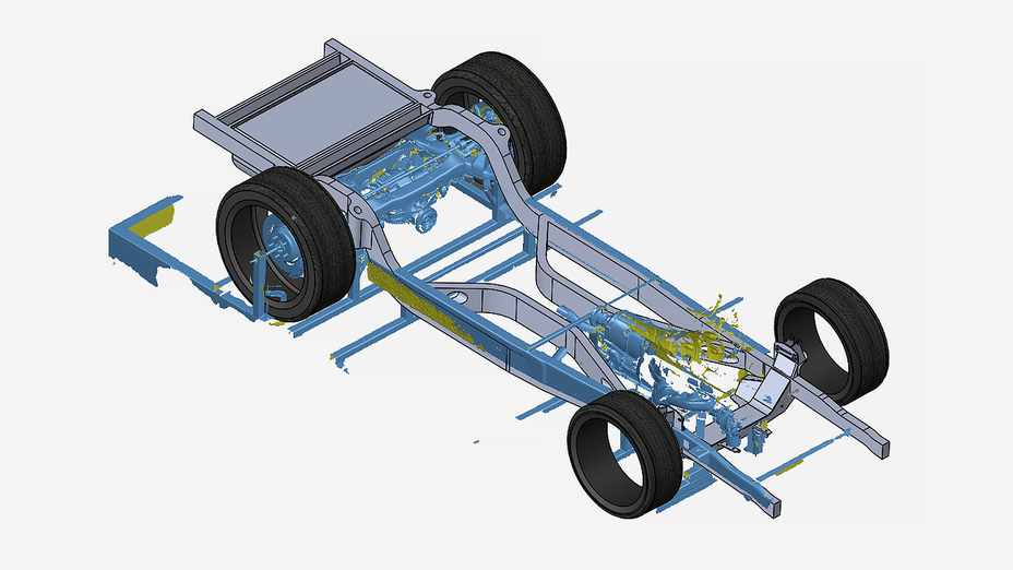
Suspension seal and frame for testing produced with polyurethane casting using Figure 4® EGGSHELL-AMB 10 and selective laser sintering in DuraForm® PA, respectively.
03 Straightforward workflow
The straightforward CAD to casting workflow begins with sending the file to print within 3D Sprint®, an all-in-one software for polymer 3D printing. The software’s extensive toolset includes options for adding supports as well as managing the printing process. Once printed, BWT Alpine F1 Team post-processes the casting shells, which involves cleaning the parts and post-curing them in the LC-3DPrint Box post-curing unit. This process takes roughly two hours and primarily consists of a 90-minute, hands-off post-cure.
After UV post-curing, BWT Alpine F1 Team coats the 3D printed casting shell in a chemical releasing agent and the shell is ready for polyurethane or silicone pouring. Cure times vary depending on the material used and can take anywhere from 10 minutes to 24 hours.
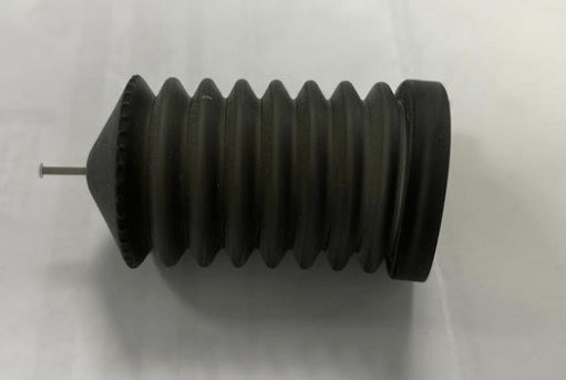
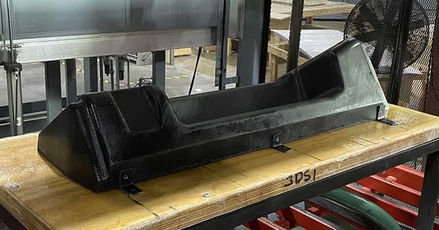
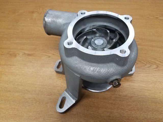
Silicone bellows like the above are being produced at BWT Alpine F1 Team for the car’s braking system.
04 Performance in a grueling environment
The performance demands on Formula One parts are extreme. Races take up to two hours, during which the entire vehicle is subjected to wildly varying temperatures, intense vibration and brutal forces. “It’s a horrible environment to put something you haven’t seen before yesterday,” said Warner, “and we are always striving for perfection. We must ensure that all our parts perform the tasks they are given.” The parts produced using 3D Systems’ eggshell molding solution meet this high threshold for performance. Warner says the surface quality is very good, which is especially important for aerodynamic parts. The ability to rapidly produce high quality, high performance parts also makes it possible for the team to now modify parts that were previously deprioritized due to the extreme time constraints of the sport.
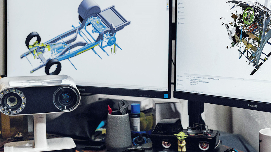
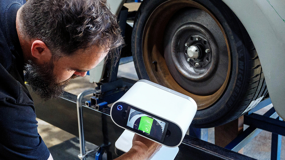
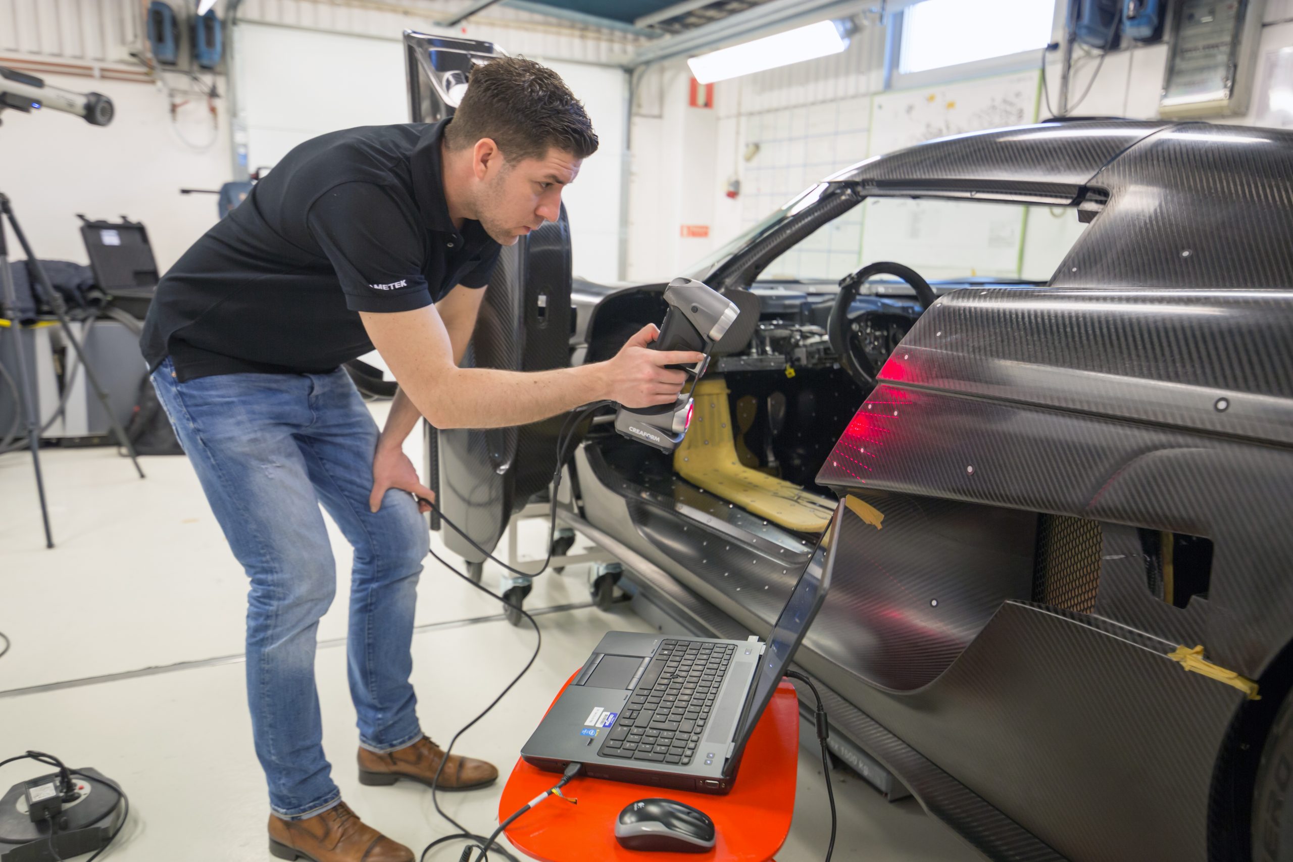
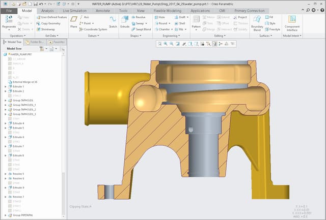
Bottom line, the benefits of 3D technologies along with dedicated software are direct and substantial over conventional metrology. Components were positioned in hours, rather than days. Time savings on measurements, increased accuracy, removing user error and unmatched traceability, are just some of the benefits of state-of-the-art measurement technology.
MRO: How to Choose the Best 3D Measurement Solution?
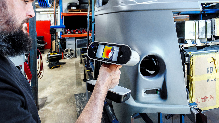
To choose the right 3D measurement solution for your maintenance, repair and engineering project, start by mapping out your current 3D measurement or inspection process, and identify the major, most recurring problems of your workflow and opportunities for improvement.
Of course, accuracy, portability and price all make great impact on decision making, but the more information you can get about the target application and the results you want to generate, the better your choice will be.
Considerations with respect to object dimensions, environment, processing speed and software compatibility will help you find the solution that best fits your needs. That way you will probably be able to start simple and scale things up along the way.
For instance, decision-makers in the aerospace MRO industry will tend to orient their choice based on the fact that the objects to scan are relatively large, that the environment greatly affects the surfaces, and that time is of the essence: the longer aircraft are grounded, the more stakeholders lose money.
Do not hesitate to reach out to various providers to ask for a demonstration and discuss your current challenges with 3D measurement specialists. Creaform offers a full suite of 3D solutions for this type of work: metrology graded, truly portable, fast and versatile. We maintain an ISO 17025 accredited in-house calibration laboratory and can provide unmatched support across the world. Creaform offers traceable solutions that will provide you measurements you can rely on.


