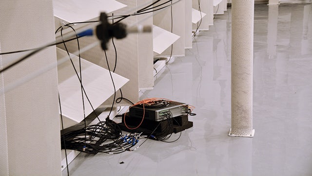
Accurately predicting the thermal performance of EV batteries is perhaps the most critical challenge facing automotive original equipment manufacturers (OEMs). Batteries have a temperature zone they can operate in to avoid failure. If the battery goes outside this zone, it can reduce the battery’s lifetime or even jeopardize occupant safety.
It is therefore no surprise that Audi, a brand known worldwide for its superior premium vehicles, has formed a highly specialized team dedicated to high voltage battery system concept development. Located in Germany, this team’s contributions are crucial to Audi’s vision of designing the mobility of tomorrow and ensuring an exceptional driving experience that is digital, electric and sustainable.
Increasing thermal model accuracy
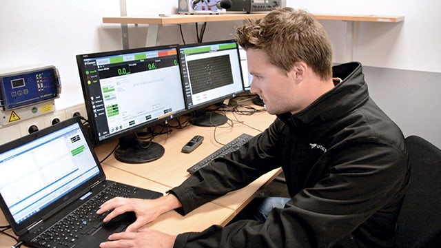
Joohwa Sarah Lee, concept development engineer, is part of this team and specializes in battery thermal performance.
“Building accurate thermal simulation models is a critical aspect of my team’s work,” says Lee. “The models themselves are very important, as they directly contribute to our goal of optimizing thermal performance of the batteries.”
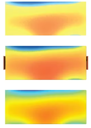
In 2021, Lee and her team discovered that, for certain cases and conditions, the simulation output did not match the test measurements. As a result, Lee set out to improve the quality of these simulation models. Lee and her team selected Siemens Digital Industries Software’s Simcenter™ Engineering and Consulting services as a development partner.
“We selected Simcenter because their tools enabled a seamless connection between not only 1D and 3D models, but also connectivity to third-party tools,” says Lee. “Simcenter Engineering Services provided the technical knowledge and support to help us set up these integrations and ensure the highest possible accuracy.”
Combining 1D and 3D simulations
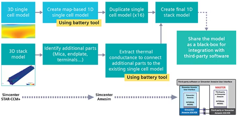
Traditionally, module and pack geometry have been modeled using 3D computational fluid dynamics (CFD) thermal simulation. This method has significant computational costs and can take days or weeks to complete. Additionally, extensive knowledge of parameters and 3D simulation experience is required to produce an accurate 3D model. Performing 1D system simulation is much faster, but it is often challenging to generate 1D models from a 3D model without compromising accuracy.
Simcenter Engineering Services set out to create a faster, more accurate battery stack thermal model to support Audi’s battery management systems, from the initial strategy development to validation with the rest of the vehicle’s subsystems. These models needed to consider several parameters, including current, coolant temperature variations, connectivity with 1D electrical models and integration with MATLAB/Simulink. Lee and her team provided the Simcenter team with test cases and boundary conditions for a variety of scenarios.
A customized workflow
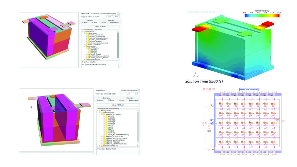
By combining Simcenter STAR-CCM+™ software and Simcenter Amesim™ software, which are part of the Siemens Xcelerator business platform of software, hardware and service, Simcenter Engineering Services experts developed a semiautomated workflow to generate a 1D system-level model in Simcenter Amesim from a 3D Simcenter STAR-CCM+ model. The purpose of this workflow was to make sure Audi’s 1D simulation users could benefit from the high level of detail provided by 3D models while also maintaining the speed of 1D simulation.
Using specified inputs, Simcenter STAR-CCM+ was used to calculate several steady state conditions covering the chosen design space, such as inlet coolant temperature, flow rate and current. The data can then be used to derive a 1D electro-thermal model for investigating transient scenarios for the complete stack.
Reducing time, increasing accuracy
The workflow developed by Simcenter Engineering Services experts has reduced the computational time of battery thermal simulations to just minutes. One of the most vivid examples is simulating an EV battery charging scenario from 10 percent battery capacity to 80 percent.
“As a result of our project with Simcenter Engineering Services, we were able to reduce the simulation time of the charging scenario from almost an entire day to less than a minute,” Lee says. “This is a huge difference in calculation time. We have also seen a significant improvement in the simulation results, especially for thermal behavior studies.
“We explored other solutions for this problem, but no other company offered the level of connectivity between tools that Siemens did. Combining a detailed 3D model in Simcenter STAR-CCM+ with the speed and efficiency of Simcenter Amesim and third-party tools supported by the Simcenter Engineering Services team provided a crucial advantage. We are also excited to explore other aspects of the Simcenter portfolio, including Simcenter Battery Design Studio.”
Lee and her team are optimistic about the future of their partnership with Simcenter Engineering Services.
“We will continue to apply our new tools and methodologies to future challenges,” says Lee. “We are thankful for the support provided by the Simcenter Engineering Services team and their willingness and ability to help us solve difficult problems.”
In the vehicle development process, it is advantageous for companies to shift left in the V-cycle as much as possible. By avoiding late-stage design changes, engineering teams can achieve significant time and cost savings and help drive products to market faster.
Artificial intelligence (AI) is an increasingly popular tool to enable engineering teams to shift left. For example, engineers can train neural networks to search through enormous amounts of simulation models and data and help identify the ideal vehicle or component configuration.
Powered by AI, the effort to shift left is more urgent than ever as the world transitions to a more sustainable future with electrification. Many original equipment manufacturers (OEMs) are in the process of transitioning from producing internal combustion engines (ICEs) to battery-powered vehicles. Each of these vehicles has years of development data and simulation models that now need to be adapted for electrification.
Neural networks for vehicle target setting
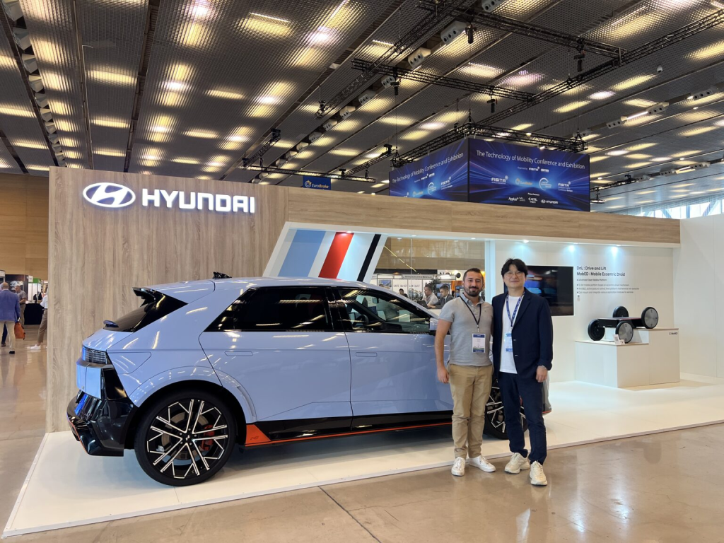
At the start of their electrification journey, Hyundai Motor Group (HMG) recognized the need to implement AI to enable a seamless shift left in the electric vehicle development process. In 2023, they partnered with Simcenter Engineering and Consulting services to build the neural networks that will enable them to define architecture-driven requirements at the concept stage of vehicle development.
Early in the design process (at the left of the V-cycle), engineering teams typically have an estimate of what they would like to see from their next generation of vehicle, including mass, size, suspension technology, etc. These early ideas need to be explored and analyzed in the most efficient way possible to define the ideal design and configuration. Target setting for attributes such as optimal mass, kinematics, drivability, ride and handling gives engineering teams subjective key performance indicators (KPIs) to meet. The earlier these targets can be met, the more time and cost savings a company can reap.
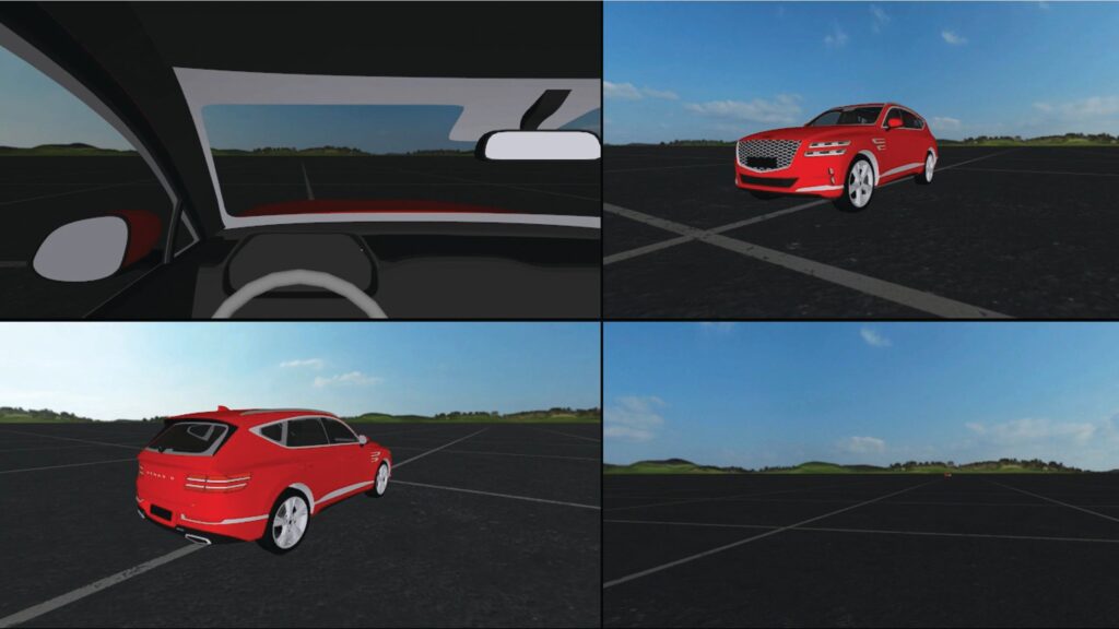
Ilsoo Jeong, comfort engineer, is part of the driving comfort virtual development team at Hyundai Motor Group. His team was tasked with target setting for chassis development of the Genesis GV 80, which will be released in a future generation as an electric vehicle (EV).
“Our goal was to achieve the best possible comfort and handling performance, so we had to consider hundreds of chassis parameters, such as mass distribution, suspension kinematics, the mounting system,” says Jeong. “We also needed to consider how these designs and configurations would need to be changed considering the ICE will be replaced with a battery.
“Additionally, we wanted the ability to perform sensitivity analyses to quickly understand how changes to the design of one component may impact the performance of others. We realized that taking advantage of AI could help us accomplish this quickly and efficiently. We partnered with Simcenter Engineering and Consulting Services to build these neural networks because they had the most expertise in Simcenter Amesim, our preferred tool, and because of their vast expertise in the vehicle development process.”
EV architecture optimization
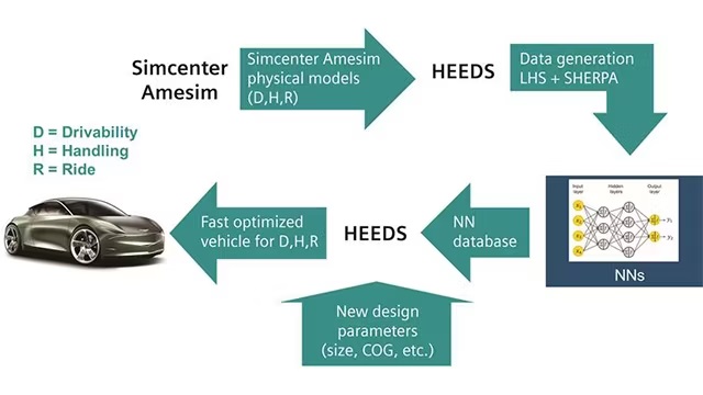
In a separate project, the Simcenter Engineering Services team had collaborated with HMG engineers to develop an architecture in Simcenter Amesim software that could be used to evaluate a variety of vehicle maneuvers and provide automatic postprocessing.
This architecture allowed criteria to be weighed separately – including 52 individual KPIs for each requirement – to achieve an overall score, and it could handle over 350 parameters as input.
In this project, Simcenter Engineering Services expanded on this work to apply it to the chassis. Using the targets provided by HMG, Simcenter engineers generated over 200,000 simulation models in Simcenter Amesim and validated them against real vehicles. They saved the simulation results in a high-performance computing (HPC) to make them run faster in the future.
“Simcenter Amesim was the driving force behind our decision to select Siemens for this project,” explains Jeong. “Only Simcenter Amesim had the capabilities to perform the number of simulations we needed, as well as the flexibility for attributes such as NVH frequency. Simcenter Amesim was also advantageous because it enabled us to work with our own templates rather than a prepackaged one. When it came to flexibility and simulation time, Simcenter Amesim was the best choice.”
Using Simcenter Reduced Order Modeling software, Simcenter Engineering Services created and trained a neural network to deliver simulation results that enables direct optimization of models later in the process. This neural network integrates with HEEDS software to assist HMG engineers in identifying the ideal vehicle configuration.
“If our targets or parameters change, we will no longer need to start the entire process from scratch,” says Jeong. “We can now find the optimal parameter set very quickly by searching through the neural network built by Simcenter Engineering Services. The ability to easily retrieve these simulation results means we can give very quick feedback to each subsystem team on the ideal configuration. Later in development, we will also be able to efficiently compare the vehicle’s driving performance to our targets by using the benchmarking data retrieved by the neural network.”
AI-enabled time savings
The collaboration with Simcenter Engineering Services and use of Simcenter software has led to significant engineering process benefits for Jeong’s team.
“Before this project, one requirement evaluation took two minutes to run in simulation,” says Jeong. “Using the neural network developed by Simcenter Engineering Services, this was reduced to one-tenth of a second. Similarly, our subsystem parameter optimization process used to take a week. With the help of Simcenter Engineering Services, this has been reduced to 15 minutes.”
Together, Jeong and the Simcenter Engineering Services team are working to reap even more efficiency benefits from this neural network. They will soon integrate with Teamcenter software to fully link to and provide traceability for parameters and requirements. This will enable a program manager with no knowledge of simulation to directly input their requirements and use parameters from a previous project to run simulations directly on the web. They can then predict system performance or optimize parameter sets for subsystems, bringing the power of system simulation to nonexperts.
“Siemens’ Simcenter portfolio and Simcenter Engineering Services will continue to be a special development partner for HMG,” says Jeong. “Our companies have a strong relationship and I look forward to collaborating on future projects.”
CETIM is a research and study center that supports many industries (aerospace, automotive, agriculture, construction, energy, oil & gas, process) in their current and future technological challenges.
Collective studies (link between academia and industry)
Study common problems for a large set of industry players to share/capitalize on knowledge/know-how
Commercial studies (service offering)
Specific engineering services for companies who do not necessarily have the tools or expertise in-house
CETIM aims at improving the competitiveness of the companies that benefit from its services/studies thanks to mechanical engineering, innovation transfer and advanced manufacturing solutions.
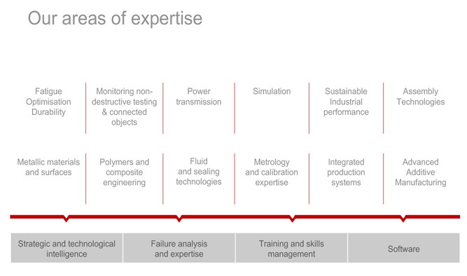
The range of skills and expertise offered by CETIM is very wide (see image below + “metallic and composite materials, surface treatments, manufacturing processes, assembly, sealing, fluid and flows, NDT, …”).
A simulation poll bringing together about thirty simulation engineers was created in 2017 under the direction of Thierry Raphenne to meet the needs of analysis in the product development phase, which are more and more prevalent in the industry.
Part 1 – Simulation team: Experts to support industry engineering challenges
Thierry Raphenne and his team ran a simulation poll on a community of experts. Thierry supervises that team of 30 people who work full time on simulation analysis projects (mechanics, finite element, CFD, DEM…). He has worked in this field since his engineering study. At CEA, his thesis established a material behavior model with finite element method. Expectations from the industry on requesting expert support from CETIM:
Validate product sizing
Understand the source of a failure. (Failure analysis, simulation helps to understand and explain the phenomena)
“What simulation brings is a better understanding of what’s going on and an acceleration of the implementation / release of products. For example, the design of a car today is done in less than 18 months versus 5 years ago. The use of simulation accelerates the process of validation and design of industrial products. Without simulation > more recurrent breakage because many fatigue situations are not considered, which are at the origin of part breakage.” – Thierry Raphenne
Simulation allows us to analyze more use-case and consequently, therefore can reduce development costs.
Without simulation, the work was done more on simplified hypotheses. This led to the oversizing of certain parts of the machine to ensure that they fitted and did not break.
Part 2: A strong link between academia and industry to meet common needs – with a particular focus on co-simulation
Collaboration among academia and industry worlds
CETIM offers the opportunity to bridge the gap between the industry players and academics, based on real-world cases coming from the industry. Those work groups allow the development of strong skill sets for the company benefiting from CETIM simulation expertise. Those transversal projects assemble up to 80 industry representatives who are then split into subgroups to work on given topics. One of the projects co-led among CETIM, the industry and the academic world is to focus on simulation and coupling.
Focus on co-simulation
For industrial players involved in that collaborative working group, it’s key to focus simulation and coupling among various types of simulation (from 1D to 3D, to couple Multiphysics with multibody type of simulation..). The aim is to verify and validate the design of a complete (and complex) system using simulation.
After this working group, the idea is to establish what are the know-how that can be easily transferred to the industrial players, based on a real demonstrator built by the team.
Part 3: The strength of Simcenter simulation solutions
The CETIM simulation team opted for Simcenter
The team chose simulation software from the Simcenter portfolio because these solutions “provide a wide range of physics, mechanical, fluidic, thermal, which allows multi-physics simulations to be performed with a single environment. Simcenter solutions are open to input/output from/to other simulation solutions.” – Thierry Raphenne
The development of a methodology to spread the use of software
“we have developed templates on the way to use Simcenter software to save time for post-processing of results, for combining constraint values. Available to all users of the software.” “There is still a lot of work to do to internally to create a strong/solid simulation community. We still need to convince non-users of the simulation of the usefulness and create a dynamic team.”
“People are more eager to trust simulation analysis when it cannot be visualized by tests (in the case of CFD for example). Highlighting of very complex, very coupled phenomena, which cannot be done in tests / allows us to popularize more the utility of simulation tools” – Thierry Raphenne
Part 4: Application cases – simulation to answer very complex engineering challenges application cases – almost impossible to test.
The industry needs is to get things done right the first time, to reduce time to market delivery with a reliable and durable product.
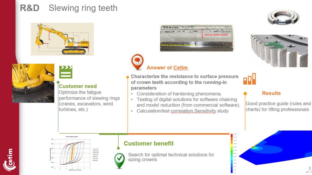
Application case 1 :
Increase the lifespan of machine parts. In the context of energy transition, being able to predict lifespan of machine parts and increase the durability of equipment.
Application case – Heavy construction machine
Application case – Heavy construction machine
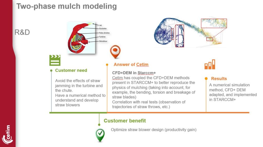
Application case 2:
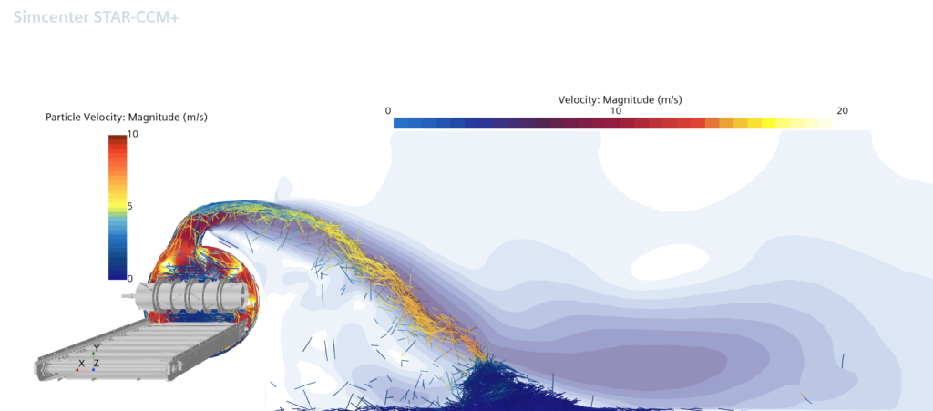
“Thanks to Simcenter STAR-CCM+ technical feature, especially on DEM application we could win new projects to support the agricultural industry”
Part 5 : Machine learning and artificial intelligence – future of simulation
The future of simulation involves the use of AI with the implementation of machine learning methods. This will be increasingly used by industry and will boost the use of simulation. Simulation will help refine and develop models in complex contexts. Benefits from studies and related results achieved on previous projects will be used to nurture new projects (part of the transverse project simulation and coupling.)
Coupling data from testing and simulations campaign will naturally follow thanks to an increasingly important use of machine learning > integration of data coming from the test bench.
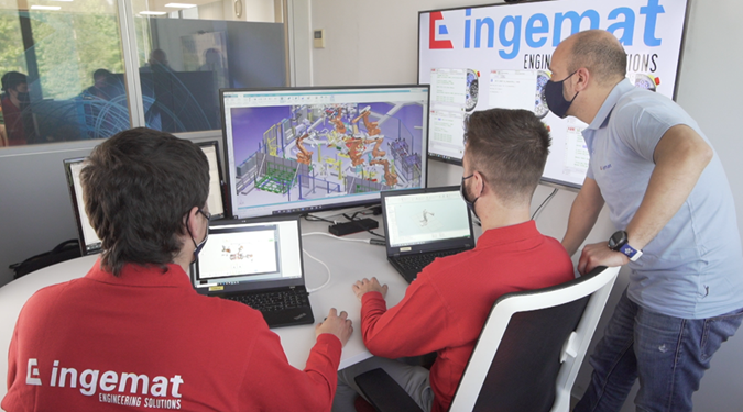
Automotive engineering company uses Tecnomatix virtual commissioning software to better meet customer requirements while driving operational efficiency.
Ingemat employees using Process Simulate software for virtual commissioning.
Ingemat is a Spanish engineering company offering robotic automation services for different industrial sectors, specializing in turnkey, tailor-made projects for the automotive industry. Their services cover installation design, erection, assembly, and commissioning to achieve the customer’s requirements for cycle time and quality. The primary technologies used in their projects include welding, hemming, bonding, clinching, and riveting.
Designing, deploying, and constructing a production line has always been based on a sequential process— The fixture installation is followed by robot installation and ensuring smooth operation with the equipment. Then, equipment and robots are integrated with programmable logic controller (PLC) automation until a qualified prototype can be produced.
But this waterfall process is time-consuming and costly, involving massive robot and control code debugging and dealing with physical installation and cabling and wiring issues. It also requires using several expensive prototype assets that are not always available on time. This makes engineers perform under restrictive time constraints and high-stress levels, especially in the automotive space, where high-quality standards are imposed.
The high standards of the automotive industry require Ingemat to work efficiently with as few errors as possible to meet timing and cost milestones. Because of this, they adopted Process Simulate in the Tecnomatix® portfolio of digital manufacturing software for robotics simulation and virtual commissioning.
“I would say, based on experience acquired in recent years, the selection of Process Simulate as a tool for virtual commissioning has been the right choice.“
Oscar Vázquez, Electrical Engineering Deputy Manager at Ingemat
Watch this video to learn why Siemens was the right choice, or continue reading below.
Process Simulate helps Ingemat drive operational efficiency
Projects at Ingemat start with mechanical design and simulation, while electrical design progresses in parallel. After completing or advancing the mechanical design and simulation to a mature stage, offline robot programming (OLP) and PLC programming will kick off, followed by virtual commissioning.
Using Process Simulate, Ingemat has realized virtual commissioning projects with different robot brands such as ABB, KUKA, Fanuc, Yaskawa, and Kawasaki – all this in connection with PLCs issued from Siemens and Allen‑Bradley, as well as custom-defined hardware.
Ingemat uses Process Simulate and virtual PLC software together for virtual commissioning projects.
This methodology using Process SimulateallowsIngemat to parallelize work and shift most of the engineering tasks to the left in the project timeline, performing them in the back office.
Enabling mechanical, robotics, and controls departments to collaborate in the same platform allows the robot programs and the automation control code for PLCs and human-machine interfaces (HMIs) to be validated in the virtual environment before their delivery to the shop floor.
As a result, the physical commissioning phase is much shorter and more efficient, requiring less debugging effort and fewer prototype assets, allowing the virtual commissioning personnel to focus on the quality of the produced assembly rather than the debugging of program code.
Why Process Simulate was the right choice for Ingemat
In a typical project, Ingemat implements virtual commissioning on a robotic zone, including up to 10 robots performing various tasks.
Once the virtual commissioning technician sets the engineering environment, it takes 2 to 3 weeks to test the production scenario and finish the virtual commissioning phase via the collaboration between the PLC and robot programmers.
Consequently, robot programs and PLC codes are validated in the virtual environment and are already in a mature state when reaching the shop floor for the first time, leading to the following:
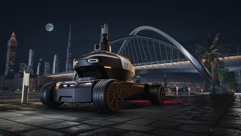
Imagine a world where communities are safer, cleaner, more efficient, and more convenient for residents.
In this world, a crime in progress can be immediately identified and reported. Groceries and food are delivered to homes without extra service fees or wait times. Trash is collected and roads are frequently cleaned with zero emissions.
All powered by robots.
It’s not the future, nor is it science fiction.
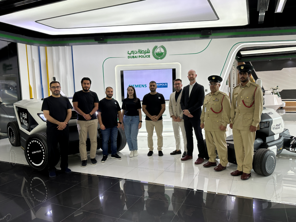
It’s happening now, and Dubai-based tech startup Micropolis Robotics is making it real.
I sat down with CEO and founder, Fareed Aljawhari, to learn more about his company and how they’ve partnered with Siemens to bring this vision to life.
Tell me about your company. What inspired you to start it?
Since I was a small child, I’ve always been fascinated with technology. You could say it’s in my blood. Funny enough, what got me interested in robotics was my discovery of a plotter back in 1996.
I remember watching a storekeeper set up a small sign and complimenting him on the artwork, expressing my admiration of the artist’s precision and quality. His response? “A person didn’t draw this, it was a robot.”
I was shocked. I asked him if he would show me the plotter and he gave me the address, so I went to see it for myself.
When I arrived, I was in awe. I must have watched that plotter run for at least 30 minutes. I asked the machine operator if he would show me how to use it. This turned into my first “job,” but because I just wanted to learn, I didn’t ask to be paid.
A few months later, I used this knowledge to get a job at a trade center operating the plotters. I wanted the job so badly that I didn’t tell them during my interview that I was underage. Of course, they eventually found out, but I had gotten so good at operating this machine that they agreed to pay my high school and college tuition fees in exchange for my work.
In school, I studied architecture, which gave me a solid foundation in design. Then I learned about product development, and eventually jumped to marketing and brand development. This led to a career as a creative director. All this experience was vital to the founding of Micropolis Robotics, as it gave me a comprehensive understanding of what a product is.
In 2012, I started my own agency with a similar idea as what is now known as the Metaverse. This was the inspiration for the name Micropolis – think “metropolis,” but it’s micro because we want to mimic a virtual city.
In 2014, I was introduced to my first investor, who also founded the Sustainable City in Dubai. He loved the idea of a virtual city, and I began developing a graphic engine to build a virtual city for Dubai.
Fast forward to 2018 and I presented a project called Microspot to Dubai Police. Microspot is a crime deterrence/prevention software we developed based on our graphic engine that we created for the virtual city. It identifies a crime in progress and uses facial recognition software to identify the person committing the crime.
The Commander in Chief loved it and asked, “What if you added embedded this technology into an autonomous patrol robot?”
I knew we could fail, but I also knew that if I didn’t say yes, I would regret it the rest of my life. So, I said yes.
What happened next?
Next, we started to research and learn how to build robots. My background is in design, so I designed a mockup of an autonomous police robot. It was good, but the Commander in Chief told us, “Great, but it won’t work for police. You need to make it bigger.” So we went back to the drawing board.
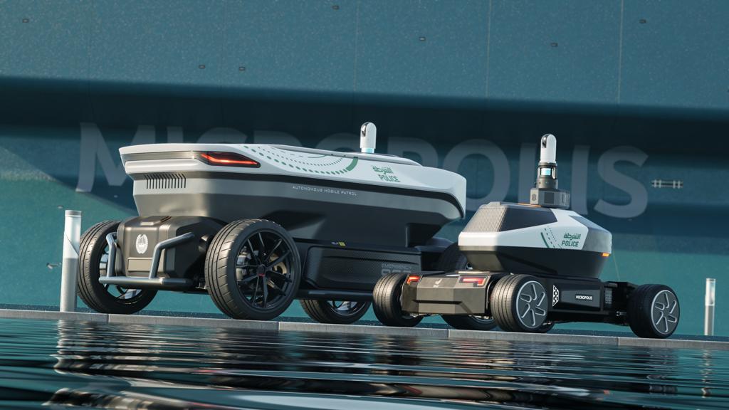
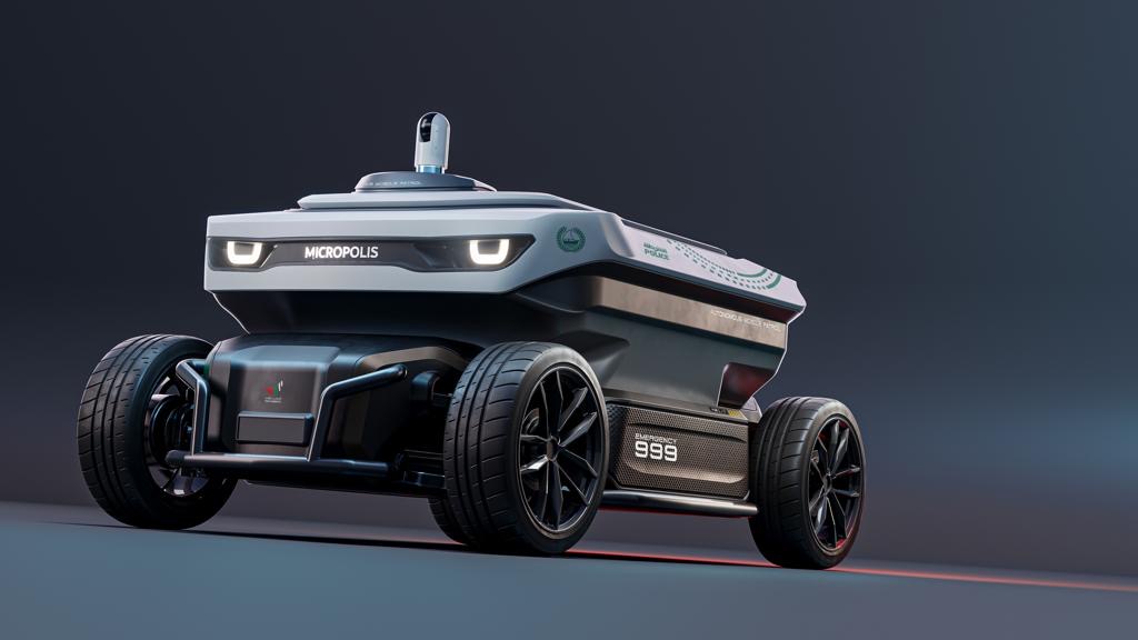
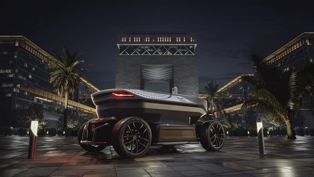
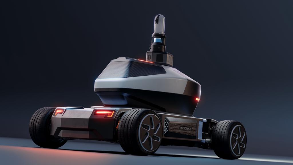
In 2021, we finalized the visual design for the M01 and M02, our first patrol robots. After that, I started looking for investors to bring this design to life.
This is where things got even more difficult. Dubai is very advanced – we have excellent infrastructure with an Internet City, Media Production City, and lots of industrial cities. And the government is very supportive of technologies like this, but the problem is we don’t have a lot of investors who are interested in tech and we don’t have a large pool of engineering talent here. You either need to attract talent from Europe and the United States, which is where engineering talent tends to be concentrated, or you have to make your own.
We hired local engineers and adopted a framework inside of our company where we allowed them to experiment and make as many mistakes as possible. We learned from each other’s triumphs and errors and eventually got organized. We now have a very professional, extremely talented team and presented the first successful models of the M01 and M02 robots in 2022.
In 2023, we received an investment from Dubai Police to build the final stage of these patrol robots, and we succeeded. It’s now a production-level robot.
The learning curve is getting shorter and shorter, our team is bigger, and everyone just got very good at what they do. I’m proud of my team. Suddenly they are all like masters of their craft.
Where does Siemens come into all of this?
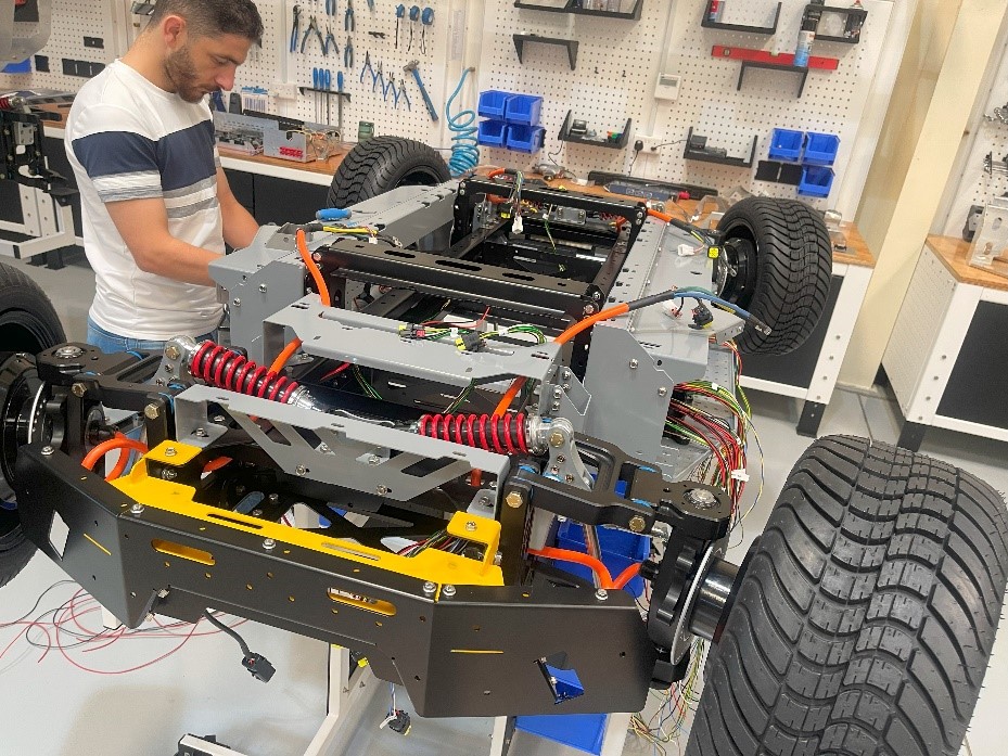
We got everything right with our robots except autonomous driving. This was the biggest challenge facing our company and we needed a company like Siemens with expertise and know-how in autonomy.
We partnered with the Simcenter Engineering and Consulting Services team to develop algorithms to help us reach Level 4 in autonomous driving. For both the M01 and M02, our plan is to develop a perception layer, including internal sensors with audiometry wheels, encoders, IMU, and steering angles, as well as external sensors such as LIDAR, cameras, ultrasonics, imaging radars, and obstacle detection.
Why did you choose Simcenter Engineering and Consulting Services for this project?
Siemens is one of those brands who, when you hear the name, you know you’re going to succeed. We selected Simcenter Engineering and Consulting Services because we needed their expertise, knowledge, and ability to get the job done right. We thought we just needed help developing some algorithms, but they’re taking our autonomous technology to a different level and have really partnered with us to develop a proper autonomous driving program.
Simcenter Engineering Services has been an incredible partner to our company. When we first contracted with them, I thought we would maybe get four or five of their engineers to work with. Instead, we get access to 26 of their engineers. It’s beyond anything I could have hoped for.
We have been delighted by the amount of expertise Simcenter Engineering Services is providing for this project. Their professionalism, organization, and level of knowledge is just extraordinary. My team and I are constantly learning from them and we are getting better every day because of them.
When will these robots be deployed?
The Dubai Police have been excellent partners and have been very flexible in their timing with us. We are hoping to launch the patrol robots in summer 2024. We would start with residential and commercial areas first with the M02 because it is smaller. We hope to launch the M01, which is the size of an SUV, in 2025.
The delivery and cleaning robots are a bit further out. We don’t have the capacity to develop all three robots at the same time, so we will take what we have developed and learned from the patrol robots and apply similar technologies to the other robot types.
Are you expanding this beyond Dubai?
Absolutely. Abu Dhabi is also interested. The Emirati Ministry of the Interior is interested. We will first focus on the UAE and Saudi Arabia, but will eventually expand to an international scale. We won’t be regional forever.
What would you say to someone who questions the ethics of using robots to do police work? Or to those who would accuse robots of stealing jobs?
My response would be that this is simply a reporting robot. It sends a picture of the person committing a crime to the police along with an identification. If it has misidentified the person, the human analyzing the picture can tell the system it is wrong. However, facial recognition software has made some incredible advancements in recent years and is almost always right. But even if the facial recognition software did make a mistake, the AI embedded into the robots will learn from that mistake and use it to get better with time.
As to whether robots are stealing jobs, it is true that some jobs will vanish as new technologies emerge. But we’re also adding new jobs that didn’t exist before and augmenting others. We’re enhancing security for residents of Dubai and improving safety for Dubai Police officers by removing the need for them to go into dangerous situations.
Robots also have the potential to enhance human lives and creativity. If I can send a robot to get my groceries, that is 20 minutes of my day that I have to focus on something else or create something new. We are not only making society safer, we are also giving people time back to think and create.
You mentioned earlier that it is challenging to hire engineers due to your location in the Middle East. Given this challenge, can you explain why you launched Micropolis Robotics in Dubai rather than somewhere else?
As an entrepreneur, I believe I have a responsibility to my region. Dubai and the broader Gulf Cooperation Council (GCC) region have been actively working to transform the technology consumers in our area into technology innovators. The government of the UAE is taking proactive steps to encourage entrepreneurs from the region to take the initiative and establish their tech firms. They’ve invested heavily in developing advanced infrastructure to foster innovation in technology and attract the best talent from around the world.
Their commitment to innovation aligns perfectly with our vision at Micropolis Robotics. We are excited to be part of this transformative journey, leveraging the promising local market demand. With GCC countries increasingly focusing on developing smart cities and enhancing the well-being of our residents, the opportunities for innovative tech products and solutions are very promising here.
Succeeding here feels like a victory.
What is the future of your company and partnership with Siemens?
Our goal is to be a tech powerhouse that develops technology to automate large operations. We think Siemens will play a huge role in all our future software development – this autonomous robot project is just the beginning. We don’t live alone in this world and recognize that we need big partners like Siemens and NVIDIA in order to be successful.
But what we’ve talked about today is just one example. Robots are just one piece of technology that is useful for humanity, and our goal is really to develop any technology that is useful for humanity.
For example, one project that is currently in the development stage is an alarm system for forests. I consider myself an environmentalist, so seeing all the recent forest fires in every corner of the earth saddens me. We are developing an idea for a sensor grid that could alert the authorities at the very start of a fire. The sensors would detect whether there is a change in the atmosphere that would indicate a fire has started. Forest authorities could then go to that location and confirm whether a fire has started and stop it before it spreads.
Our overarching goal is to develop technologies that better humanity and the planet.
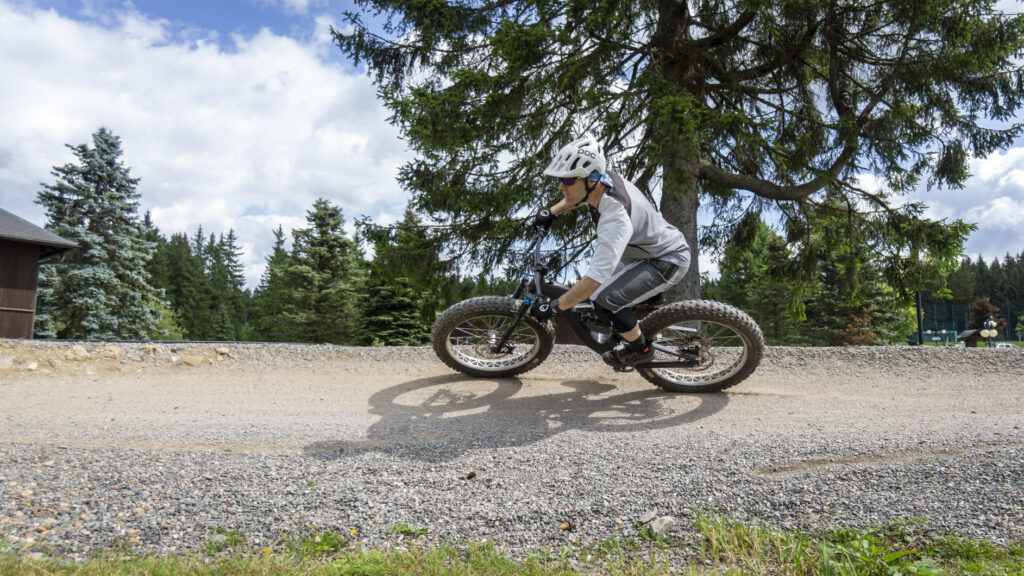
How a mountain bike enthusiast designed and manufactured his custom carbon fiber bike from scratch with Siemens NX
Siemens is not only offering products to big companies, but also small and medium businesses and even private persons can subscribe and benefit from the Siemens Xcelerator portfolio of software and services. This is what this case demonstrates:
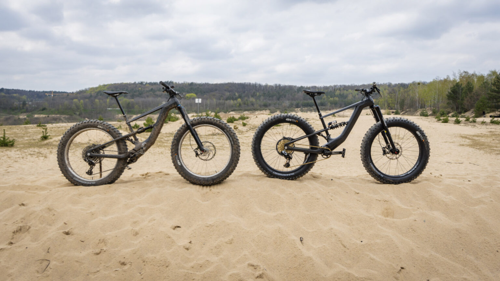
We recently found out about the project completed by a German mountain bike enthusiast, who calls himself Uncle Bob, and his journey that started with an empty screen and ended with custom self-built carbon fiber mountain bike.
Uncle Bob’s journey
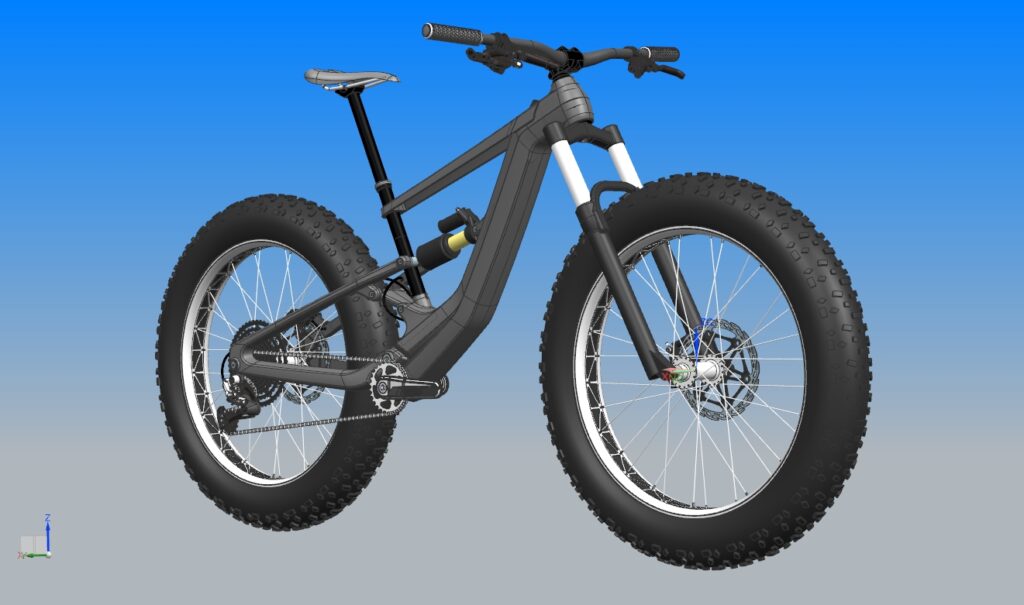
Due to an injury from biking, Uncle Bob needed a new project to keep himself entertained. He is the founder of an engineering consultancy, which is why he owned the Siemens NX CAD software and has experience with it. So, in his free time he just started directly scribbling in Siemens NX with a try and error approach and with the following weeks, his ideas became a solid concept.
Bob was especially delighted with the plentiful and individual 3D visualization options NX had to offer, they enabled him to work creatively and to see the realistic result of his design before building.
Considering the design, Uncle Bob has gone for a form follows function approach: “If something already looks like something that will not last, it surely will not last during tests.”
Why NX?
Apart from the design aspect, he really appreciates NX for the ability to test and verify his CAD design data into finite element analysis (FEA) simulation tools, which he uses in his daily professional life as well as with this bike. “I have not regretted the investment for Siemens NX, it was worth it and definitely helped me to ease up processes. Before NX, I had to copy data manually from program to program. The implementation of NX at Daimler got me starting to look out for better solutions.”
So, an FEA study was done to stress test the frame and structure. After all, mountain bikes like these need to withstand high physical forces due to big jumps, loose ground and high speeds. And his bike did!
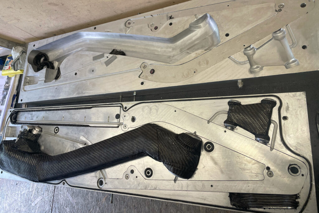
For example, his calculations resulted that the frame around the bottom bracket can withstand jumps or falls with more than 6,000N. For the areas that failed his tests, the layup of the composite material was modified in Siemens NX and additional plies were added to strengthen these areas.
Getting started and getting building with NX
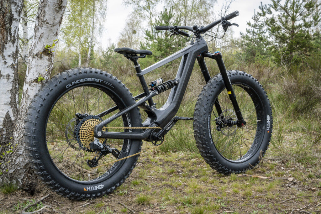
With a flaw free concept ready, he designed an injection mold in Siemens NX that he could use for producing the carbon-fiber parts. Due to the extensive 3D features in Siemens NX, he could make the mold as material efficient and small as possible. Then he started working in his garage: A wax core was casted that represents the inner geometry of the carbon frame. Then, he wrapped the carbon fiber around it and closed the mold airtight. Using vacuum and high pressure a hardening resign was injected into the mold. After a few hours of tempering the resign was hardened and with higher temperature the wax core melted and flowed out. Now the frame was made. He didn’t clearcoat the frame because Uncle Joe was confident enough that his construction and his materials used were sufficiently durable anyway.
After that, the frame was made and he started to assemble all the custom frame parts and bought standard parts together. A few weeks later it was all done, a extreme mountain fat bike, that all-in-all only weighted 17kg, with the NX constructed custom carbon forged frame only taking 3kg part of that. After his first test ride, Bob was beyond impressed:
“Insane! Sore muscles in the face because of the permanent grin. I can only say: Dreamy. The bike fits me like a glove.”
The strength of Siemens NX
This business case shows the accessibility, exactness and prediction powers of Siemens NX. Building something from carbon-fiber was a task that only large manufacturers would consider just ten years ago. With Siemens’ NX, now even talented designers can plan and design flaw free carbon structures from scratch at home.
Nearly 20% of all road accident fatalities in the EU are pedestrians. Car manufacturers all over the world want to improve pedestrian safety. In this blog, we share the story of the world’s leading mobility engineering experts, the EDAG Group AG in Germany.
Remember those adverts where a car drives into a wall, and the crash-test dummies inside are left intact? If you watched closely, you might have noticed that different dummies are used in different tests. This is because they are highly calibrated for each test, and any changes will affect their validation. You might have also noticed that the acceleration given to the car is always in one direction. This ensures the dummy does not change position before impact. The dummies are passive objects and can not reposition themselves. A test is ruined if they move out of position before the impact.
Using dummies comes with three problems
Firstly, you can’t test until you have built a complete physical prototype. Secondly, you will need to destroy multiple vehicles to complete all the validation tests. Thirdly, you can not quickly test pre-crash maneuvers such as lane change.
From physical to virtual dummies
A few decades ago, manufacturers had to crash over a hundred vehicles while designing a single model. Today, only a fraction of that number is required. With the use of virtual models, engineers can design new, safer models quicker and more cheaply.
Simcenter Madymo simulates both dummy and human models, including models that can reposition themselves after and during a maneuver. It integrates Multibody Dynamics, Finite Elements, and CFD technologies in one single solver that includes a database dummy and human models that can be scaled to any size or to population percentiles.
This means that not only can you get the most realistic assessment of what will happen to occupants and pedestrians in a collision, but you can also carry out testing much earlier in the development phase. Once you have your virtual vehicle model, combine it with your Simcenter Madymo model, and you’ll get accurate test results before you’ve built a single prototype.
Crash Test Innovation of the Year
In 2021 Simcenter Madymo was named the ‘Crash Test Innovation of the Year’ by ATTI magazine. It is no wonder that more companies are turning to this simulation software to aid vehicle design.
Keeping pedestrians safe
EDAG Group supplies mobility engineering expertise to the worldwide automotive industry. Its CAE and Safety department specializes in attaining the highest safety levels for vehicles and meeting legal requirements and customer ratings for particular regions or companies.
The Active Hood is a common pedestrian safety solution for minimizing head injuries when a pedestrian is struck by a car. By automatically lifting the hood when a collision is detected, a space is created between the inside surface and the rigid components underneath. This ensures that when the head hits the hood, the head is much less likely to suffer serious damage.
But to develop an effective Active Hood, engineers need to understand exactly how a human body will behave when struck by that vehicle.
This is where Simcenter Madymo comes in
The CAE and Safety department, led by Stefan Hundertmark, uses Simcenter Madymo to simulate the kinematic behavior of pedestrians’ bodies in accidents to help their customers develop the safest possible vehicles. Read the case study to discover how Simcenter Madymo allows them to significantly reduce simulation time for human body behavior from days to hours while meeting all the necessary standards and regulations in pedestrian safety performance.
You can also find out more about how Simcenter Madymo enables manufacturers to meet regulations by watching the pedestrian safety systems webinar featuring Assistant Professor Corina Klug of TU Graz and Cindy Charlot, technical lead of the Safety and Comfort Modeling team of Simcenter Madymo. Corina Klug was instrumental in creating the Euro NCAP guidelines, which reduced EU pedestrian fatalities by 36%. Cindy explains how to use Simcenter Madymo in the validation process and how to comply with all certification requirements.
Vision Zero
The ultimate aim for The EDAG Group and other companies using Simcenter Madymo is to eliminate all traffic fatalities and severe injuries.
That might sound like a pipe dream, but it forms part of a global movement known as Vision Zero.
The campaign began in Sweden in the 1990s and has since proved successful across Europe and is now gaining momentum in the United States.
First and foremost, it challenges the traditional belief that road traffic deaths are inevitable and that saving lives is expensive. Vision Zero accepts that human failure and collisions will happen, but with a systemic approach, we can prevent fatal and severe crashes that lead to deaths.
Simcenter Madymo is a key element of Vision Zero as its occupant and pedestrian safety simulations help manufacturers design vehicles that offer the most protection.
Car manufacturers such as Volvo incorporate zero accidents in their vision. The basic philosophy of the Volvo Group Safety Vision is that accidents can be prevented. At the same time, they are aware that many things are outside of their control. This is why collaboration with other players is important. And change is happening. Also, suppliers such as ZF or Continental go the extra mile to contribute to the zero fatalities future. For more information, read this article on how Continental is heading for Vision Zero.
Pedestrian safety and ADAS & autonomous vehicles
Don’t be mistaken by thinking that ADAS (Advanced Driver Assistance Systems) and fully autonomous vehicles will render accident simulation obsolete.
In fact, they make it even more important.
Even with self-driving vehicles, collisions will still happen. The artificial intelligence controlling the vehicle needs to be able to minimize injury and calculate the best course of action in a split second. It’s no use swerving to avoid one car if that takes you into the path of several cars and causes a bigger crash.
Using Simcenter Madymo, developers of these systems can train them to maximize occupant and pedestrian safety. By understanding exactly how human bodies will be affected by collisions, AI can determine which action will result in the least injury. So instead of swerving, it may simply choose to brake. While not avoiding the collision completely, the reduction in speed, combined with ensuring airbags fire at the right moment and the seat belts do their job, will be enough to prevent serious injury. Ultimately, it will lead to fewer deaths, which is the number one priority on the path toward Vision Zero.
Today to celebrate the fifth UNESCO International Day of Education, we want to highlight quite an exceptional story from the InMotion student team that just happens to use Siemens software – and of course: Simcenter.
Although InMotion has made a serious technical impact with its all-electric, track-ready Le Mans race car, the Revolution, the real beauty of this story is what this team of students has accomplished with their 12-minute fast-charging technology and next-generation battery packs.
Based on the Automotive Campus in Helmond, The Netherlands, InMotion is closely associated with the Technical University of Eindhoven. The InMotion team, which is run as a foundation and rotates students annually, practices continuous innovation. Experienced former members meet weekly with the current team to guarantee knowledge transfer and help solve technical challenges.
Moving forward and making progress
Over its ten-year history (plus), InMotion has built four, successive innovative race cars, including the heritage bio-ethanol Ignition, the fastest student e-Formula 3, the Fusion, the Vision, a more aerodynamic e-concept car and the Revolution, a true pioneer with its 12-minute e-charging time – that is faster than an e-Porsche or even a Tesla.
“Ten years being a student team is quite amazing. I think this is what makes InMotion special. The people that founded it ten years ago are still on the supervisory board. People that built the first electric race car, the Fusion, are still providing us knowledge on the Revolution. That’s unique. It’s about moving forward, making progress, and keeping continuity in the team,” states Ewout Timmermans, former Team Manager, InMotion.
Digital twin work experience
Working in a digital thread with a digital twin was new to some of the engineers on the team. Old school tactics, like prototyping and on-the-fly troubleshooting, are things left in the past for the new generation of InMotion engineers.
“I think for most of the engineers, it was a true eye opener that you can work in this detail and represent advanced design and engineering performance this accurately in a virtual world,” explains Thomas Kuijpers, former Technical Manager, InMotion.
The team is quick to point out that getting everyone up to speed on all the SiemensXcelerator tools, pretty much the same package that many F1 teams use, btw, was far from an out-of-box experience. They had help from cards PLM Solutions, a Siemens Platinum Smart Expert Partner, based nearby in Best, The Netherlands.
“The consultants from cards PLM were always really quick to respond and help point us in the right direction when we got stuck,” explains Kuijpers. “Another plus point about Siemens, especially for students, is the Siemens Xcelerator Academy. Most of us had already followed courses online with university, but once we started working as a new team, we even had more access to more specific material and tutorials. This was very useful for us.”
Innovation on the mobility side
“We really try to innovate on the mobility side. We believe that fast charging is way too slow at this point, and that might be a reason that people do not drive electrically,” explains Martijn Scholtus, former Account Manager, InMotion. “With the Revolution, we want to make the charging time as fast as possible. It is charging in 12 minutes. That’s a big leap. And it’s a Le Mans race car.”
“The most prestigious race is the 24 Hours of Le Mans. It is really a dream of the entire team to race there with this technology.” Adds Scholtus, “If it works at the 24 Hours of Le Mans, then it’s going to work everywhere.”
The importance of hands-on experience
Clearly the InMotion team has put its footprint on the power of innovative technology and, without forgetting International Day of Education, the importance of getting out of the classroom for some hands-on experience and on-the-job training in the world of engineering education (or any higher education for that matter). But more importantly, the team shares passion for engineering innovation to make the world a better place. And, at Siemens and Simcenter, all we can say is that we are happy that we could help.
A short InMotion Photo Gallery
A rotating student team going into its 11th season, InMotion aims to inspire students, organizations, and society with its unique concept to accelerate the energy transition in the automotive industry. The team’s vision is to make future charging as fast as “filling up”. To showcase its unique electric refueling technology, the team is setting a goal to race in the toughest endurance racing environments, the 24 Hours of Le Mans.
The simulated top speed of the Revolution is 300 km/h. Either way, it definitely outpaced our famous technology demonstrator, the Simcenter SimRod, on the track. (Although you have to argue that even though SimRod never set out to be a famous race car with a need for speed, it can pack a bit of punch…and keep up with the big guys.)
Product: Simcenter Industry: Automotive and Transportation
Working in partnership with Siemens, UTAC CERAM is looking to the future of automotive acoustic design, including virtual homologation, predictive pass-by noise design and sound optimization of AVAS-fitted vehicles.
Louis-Ferdinand Pardo, Acoustic Expert Leader and Department Manager, Electromagnetic Compatibility and Noise, Vibration and Harshness UTAC CERAM
Passing the first time
Scientists are confident that noise pollution can harm the health and behavior of all beings, so reducing the noise levels generated by cars, airplanes and machines is a requirement for supporting a sustainable future.
Governments worldwide, especially in Europe, are taking drastic measures to enforce more stringent vehicle pass-by noise (PBN) levels. In June 2016, Europe issued a plan for diminishing regular passenger car noise levels from the current level of 72 decibels (dB) to a maximum of 70 dB by 2020 and 68 dB by 2024. Achieving a 4-dB reduction will take an enormous effort, as vehicle manufacturers are already pushing engineering limits to remain below the current target.
Vehicle manufacturers and part suppliers will simply have to work hand-in-hand to deliver systems that meet individual and overall acoustic targets. Special attention will have to be given to the components generating the most noise: the powertrain, intake, exhaust and tires.
Every vehicle needs to be certified by the International Organization for Standardization (ISO) 362 standard, which has been revised in recent years. It now requires more extensive tests in order to even better represent the reality of urban traffic. Testing teams are already spending lots of effort on performing the regular homologation tests and have little to no time or resources to spare.
The reality is clear: Vehicles need to be designed to be able to pass the test the first time.
Getting ready for the future
For decades, UTAC CERAM has helped vehicle manufacturers pass certification and homologation tests. UTAC CERAM is a private, independent group providing services in many areas of land transportation: regulation and approval, testing and technical expertise (environment, safety, durability and reliability), certification, public automotive events and driver safety training. UTAC CERAM also works in an official capacity with two French regulatory institutions that oversee standards for roadworthiness (Central Technical Organization) and standardization (Office for Automotive Standardization).
Over 400 employees work at two test centers in Linas-Montlhéry and Mortefontaine, France, as well as at customer sites in France and abroad. In addition, UTAC has subsidiaries in the United Kingdom, North America, Russia and China.
Vehicle pass-by noise homologation is one of many UTAC CERAM activities. Numerous vehicles are tested each year according to the ISO 362 standard on the exterior pass-by noise track at the Linas-Montlhéry site. Yet UTAC CERAM’s involvement in the automotive industry goes beyond simple homologation. The company offers solutions for automotive design and testing so manufacturers can be confident their vehicles will pass the ultimate homologation test.
For the purpose of mastered pass-by noise design, UTAC CERAM has invested in a state-of-art acoustic chamber. The large facility features fine-tuned sound insulation, a four-wheel drive roller bench and two rows of microphones combined with Siemens Digital Industries Software’s Simcenter Testlab™ software for analysis and Simcenter SCADAS™ hardware for acquisition. As such, it is designed to reproduce the conditions of exterior pass-by noise tests as accurately as possible.
The benefits of indoor pass-by noise testing are huge. Indoor pass-by noise testing lets teams perform accurate, perfectly reproducible tests in a controlled environment, independent of changing weather conditions. Since vehicle speed and gear shift are robotized, risk of human driver error is eliminated. However, tire noise is more difficult to accurately reproduce in a room, as it sounds different on a roller bench than it does on road surfaces. This is why Simcenter Testlab Pass-by Noise Testing software, part of the Simcenter™ portfolio from Siemens, features a tire noise model calculation that corrects tire noise data according to the ISO 362-3:2016 procedure.
Thanks to the repeatability of tests, results are more reliable. In the intermediate term, it is expected that indoor pass-by noise tests will be performed for vehicle homologation and will complement or replace exterior tests. Louis-Ferdinand Pardo, acoustic expert leader and department manager of electromagnetic compatibility (EMC) and noise, vibration and harshness (NVH) at UTAC CERAM, confirms this trend based on his experience as a member of the ISO committee defining the standard for pass-by noise level.
But the benefits of indoor testing go beyond eliminating the occurrence of chance, errors or incidents in a test. Testing in a controlled environment allows the user to implement advanced pass-by noise engineering techniques. The noise contributions of individual sound sources, such as powertrains, exhausts and intakes, can be evaluated and calculated to help set precise acoustic targets for the components.
Shaping the sound of electrical vehicles
Vehicle sound design is not about the reduction of noise levels alone. Today, an increasing number of hybrid and electrical vehicles are being used in urban areas. These vehicles drive fairly softly. The risk of accidents rises when no sound alerts pedestrians or cyclists of the presence, speed and direction of an approaching car. To preempt this risk, governments and institutions have been debating the necessity of equipping hybrid and electrical vehicle with noise-generating warning devices described as acoustic vehicle alerting systems (AVAS).
In 2016, the United Nations (UN) published a new regulation (UN 138) on minimal noise requirements that would enforce the fitting of such systems on new vehicles within a couple of years. In the same year, the United State National Highway Traffic Safety Administration (NHTSA) drafted a final rule establishing the federal motor vehicle safety standard (FMVSS 141) of minimum sound requirements for hybrid and electric vehicles.
Testing of AVAS-fitted cars will be best performed indoor as noise levels are by definition low and background noise should be excluded. Simcenter Testlab Interior Pass-by Noise Testing supports the definition of minimum noise levels by integrating the ISO 16254 standard (Acoustics – Measurement of sound emitted by road vehicles of category M and N at standstill and low speed operation – Engineering method) in its worksheets. With its state-of-the-art acoustic facility equipped with Simcenter testing solutions, UTAC CERAM is well positioned to support manufacturers of hybrid and electrical vehicles design sound for the alerting system.
Optimal testing productivity
To perform an indoor pass-by noise test, the vehicle is positioned and secured on the four rolls of the roller bench. The vehicle stands in the middle of the large chamber with two rows of about 20 microphones, each positioned on the sides of the chamber at an exact distance of 7.5 meters from the vehicle and a height of 1.2 meters. The microphones send their signals to the two Simcenter SCADAS hardware mobile data acquisition systems, part of the Simcenter portfolio, at each side of the room. Once the vehicle is positioned on the roller bench, the engineer starts the test. From that moment on, most of the procedure is automated. The engineer leaves the acoustic room for the control room, where he or she will be able to set up the parameters for the test and run it remotely. If necessary, the test can also be adjusted and started manually from a control box in the room.
At UTAC CERAM, the installation has been designed to ensure maximal testing productivity.
“We have selected the Simcenter testing solutions from Siemens for three main reasons,” says Pardo. “First, it offers excellent data quality and processing capabilities for indoor pass-by noise with algorithms that deliver accurate results, comparable to the ones obtained with actual exterior pass-by noise tests. Second, using Simcenter testing solutions ensures continuity and compatibility of tests performed indoor with tests executed outdoor with similar Simcenter systems. Third, we really appreciate the long-standing partnership with Siemens for acoustic engineering and testing.
“Siemens’ involvement in pass-by noise engineering is not limited to supplying measurement equipment; the company acts as a partner in research and development, providing solutions for acoustic source quantification and evolving towards early, predictive vehicle pass-by noise design. Siemens is also involved, as am I, in the definition of tomorrow’s ISO certification procedures, moving towards virtual homologation.”
Performing state-of-the art tests and beyond
New ISO certification procedures prescribe more exterior tests at run-up and constant speeds, and in various gear ratios. Those requirements can be reproduced in UTAC CERAM’s acoustic chamber, which allows the user to assess a design variant as well as prepare for vehicle homologation. Test procedures are preprogrammed in the chamber’s controller: the engineer only adjusts the parameters according to the requirements of the vehicle under scrutiny, opens the Simcenter Testlab worksheet and initiates the test. It then runs autonomously, with triggers starting and stopping measurements in Simcenter Testlab. Yoni Meyer, test engineer at UTAC CERAM, is an enthusiastic user of the software: “We benefit from almost all the implemented functionalities of Simcenter Testlab, and despite being advanced users, we still appreciate the easy-to-use worksheets and intuitive workflow approach.”
By using the postprocessing capabilities of Simcenter Testlab, further tasks, such as separation and quantification of noise sources, can be performed. The result is being able to clearly identify the noise contribution of individual components. This analysis will allow exact acoustic target setting on components, and means in the future the user will be able to accurately predict vehicle pass-by noise level based on component noise contribution.
Pardo concludes: “Working in partnership with Siemens, UTAC CERAM is looking to the future of automotive acoustic design, including virtual homologation, predictive pass-by noise design and sound optimization of AVAS-fitted vehicles.
We benefit from almost all the implemented functionalities of Simcenter Testlab, and despite being advanced users, we still appreciate the easy-to-use worksheets and intuitive workflow approach.
Louis-Ferdinand Pardo, Acoustic Expert Leader and Department Manager, Electromagnetic Compatibility and Noise, Vibration and Harshness UTAC CERAM
Product: Tecnomatix Industry: Automotive and Transportation
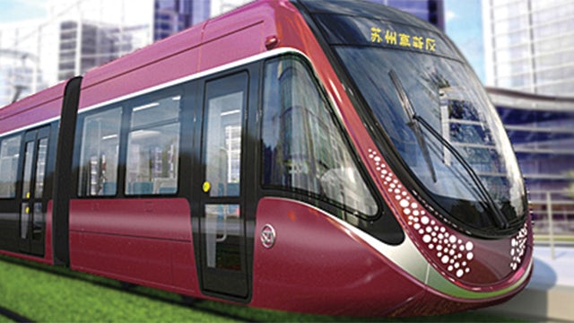
CSR Nanjing Puzhen Co., Ltd. (Puzhen), which was founded in 1908, is a research and manufacturing enterprise and an integrated service supplier for railway transport of passengers and urban rail transport equipment in China. The firm manufactures urban rail transit vehicles, intercity multiple units, modern tramcars as well as passenger cars and important core parts.
As China began to renovate its rail transit lines and expand urban/intercity rail transit transportation in 2004, Puzhen entered a period of tremendous growth. In 2014, the company’s annual sales hit ¥10 billion, up from less than ¥2 billion in 2004. In 2015, Puzhen officially kicked off the mass production of its 200 kilometers per hour (km/h) class intercity high-speed train for the Guangdong province.
In addition to a continued boom in the rail transport equipment manufacturing industry, the rapid growth of Puzhen is also attributable to its persistent efforts in research, development and manufacturing to improve its ability to innovate. Puzhen started to implement lean management early on, and has applied advanced information and digital systems such as computeraided design (CAD), computer-aided manufacturing (CAM), product data management (PDM) and enterprise resource planning (ERP) in the research and development (R&D) and manufacturing processes to facilitate efficient and collaborative integration between design and manufacturing.
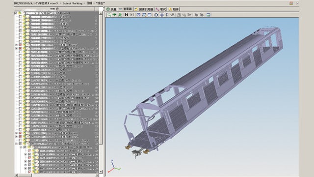
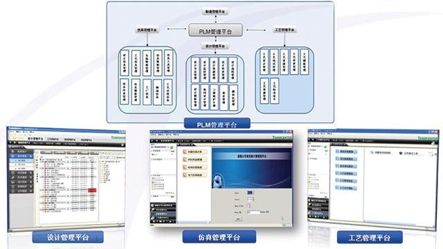
In 2013, Puzhen decided to implement two solutions from product lifecycle management (PLM) specialist Siemens Digital Industries Software: Teamcenter® software and the Tecnomatix® portfolio. The objective was to enhance planning, better manage and control design development projects, improve collaboration across design processes, and increase process quality and productivity. Two years into deployment, the company has realized significant achievements in design and manufacturing collaboration throughout the product lifecycle. In addition, it has built a uniform and comprehensive information-based R&D and manufacturing process, greatly enhancing innovative product R&D and manufacturing.
Puzhen uses Teamcenter for lightweight design and process planning based on full 3D models.
Allying with Siemens Digital Industries Software
Puzhen has a tradition of conducting solid technical research and information management. During the past decade, the company worked on the construction of a digital design and manufacturing platform. It adopted 2D and 3D CAD software and simulation analysis software for digital product design, and invested millions in building a PDM system that would enable sharing of design resources. Puzhen built an R&D system and testing platform adapted to its lean management idea. The company developed and implemented a science-based, practicable business information system for strategic planning. Based on PLM and select information technologies, Puzhen has realized integrated innovation in finished vehicles, and mastered core technologies in areas such as network control, aluminum alloy and stainless steel body manufacturing, as well as bogies and brakes.
The problem was that the prior software tools and PDM system needed to be upgraded due to insufficient standardization and lack of application depth. Puzhen’s early PDM system, though lightweight, convenient and sufficient for basic data and process management, was unable to be scaled up to cover other business units, including process and manufacturing. Therefore, Puzhen decided to introduce a more complete and powerful PLM system to help with collaboration and integration, from R&D and design to process planning and manufacturing.
After a long, detailed evaluation and analysis of similar companies and products both at home and abroad – based on technical capabilities, industrial experience, service abilities, costs and other considerations – Puzhen determined that solutions from Siemens Digital Industries Software could best meet its mid- and long-term applications requirements.
Teamcenter is a powerful collaborative product data management (cPDM) solution that has been applied extensively by large and mid-sized manufacturers all over the globe. Teamcenter enables enterprises to accelerate implementation, increase productivity, enhance collaboration both inside and outside of the company, and expand control over the entire product lifecycle process, while its uniform architecture provides enterprises with a complete end-to-end PLM solution.
Tecnomatix is a digital manufacturing system that integrates product R&D and design with process planning, process simulation and verification, and manufacturing execution. The combination of these two solutions is a perfect match for Puzhen to meet its requirements for in depth collaboration in R&D and manufacturing.
In addition to the powerful solutions and functions provided by Teamcenter and Tecnomatix, Puzhen points out that Siemens Digital Industries Software’s extensive experience working with large and mid-sized enterprises, especially those in the rail transport equipment manufacturing industry, as well as the technical service abilities of its implementation and after-sale teams, also played an important role in the decision. Siemens Digital Industries Software has accumulated a wealth of PLM project planning and implementation experience as its solutions have been widely applied in many well known manufacturing enterprises in China and throughout the world. Siemens Digital Industries Software is a significant participant in the global rail transit market with extensive practical engineering knowledge in business process features and information-based planning.
After two years of cooperation, Puzhen points out that, from the start, Siemens Digital Industries Software provided it with comprehensive PLM experience, highly effective technology products and important implementation/consulting services. During the midterm deployment and implementation process, Puzhen notes that Siemens Digital Industries Software helped it realize truly efficient project management and execution.
Puzhen’s design, process and simulation platforms form a closed-loop data process management system.
Building an integrated platform
By deploying Siemens Digital Industries Software’s solutions, Puzhen intended to optimize design and process management, improve R&D efficiency and increase process simulation capabilities in order to meet both the market demand for rapid development and the company’s internal requirement for lean production. To that end, the leadership at Puzhen attached great importance to the implementation of the PLM project, repeatedly discussed the project at the company’s strategic meetings and kept a close eye on project execution. At critical project junctures, the leadership sought debriefings by the implementation team. The leadership required that the PLM project take the company’s business features into full account, thus thoroughly solidifying the management mindset of lean R&D.
With such attention and support from the company’s leadership, Puzhen has successfully motivated the staff to participate across management and technical levels. The implementation of the PLM project was headed by the technical information department, and a full-time project implementation team was formed consisting of key business personnel from the information, design, technology and other departments. The technical information department was tasked with overall control, management and promotion at all stages of implementation, while the design and technology departments mainly focused on assisting with solving business problems and relevant user testing work.
Siemens Digital Industries Software provided guidance and support throughout the process, delivering special insight in key impact areas, including technology, business, knowledge training and team management.
Using collaborative efforts at multiple levels, to date, Puzhen has implemented management projects for design, process, testing and simulation. Currently, the company is extending such projects to manufacturing sites and other disciplines within the organization.
The PLM system has been used to build four major platforms: design, process planning, simulation and testing. In total, 102 projects have gone live, enabling Puzhen to collect and use extensive platform data, improve design quality, significantly reduce design and process planning cycles, and cut down manufacturing and purchasing costs.
Puzhen has used Teamcenter to form a closed-loop information flow that has helped it realize six unifications and a single integration. The company has unified its product design data platform based on project management, R&D process control, the design resource platform (code, standard and interchangeable parts library and template), engineering change platform, file management for the release and storage of electronic drawings, and design simulation and testing verification platform; and Puzhen has integrated its data chain of design, process and production.
The six unifications and single integration have helped Puzhen:
Build major platforms for design, process and simulation, forming closed-loop data process management
Implement design management platform functions for file coding, file review and approval, design resource, file template, project data and electronic filing
Realize lightweight R&D and process planning based on full 3D models
Deliver integrated, platform-based engineering bills of materials (EBOMs), preliminary bills of materials (PBOMs), manufacturing bills of materials (MBOMs), enabling data source consistency and output standardization
Establish a structural assembly process, allowing engineers to directly view and use the design part information (including 3D design data), and to view complete upstream/downstream assembly relationships and sequences, with real-time process design facilitating quick, enlightened decision-making
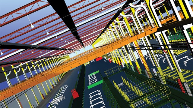
Establish a shop floor simulation layout plan based on virtual reality and simulation technology, enabling the company to model a design or production process of a product in a unified and detailed fashion; utilize fully digital product design, processing, assembly and verification; and simulate the complete product lifecycle
Potential bottlenecks, critical paths and logistics issues are now readily identified, enabling increased production and improved equipment utilization. This notably reduces costs and increases competitiveness. Using the Teamcenter and Tecnomatix combination, Puzhen has shortened the design cycle by 30 percent while doubling stock utilization.
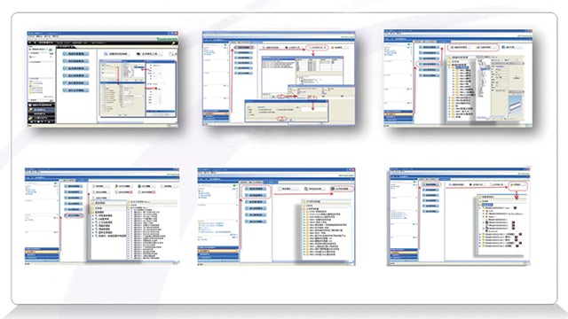
Puzhen’s design platform enables the highly efficient management of functions: file coding, file review and approval, design resource, file templ ate, project data and electronic filing, etc.
Puzhen simulates a 3D digital plant using Tecnomatix.
In the near term
The use of Teamcenter has provided great support for business data management, business process solidification and efficient product design, while enabling the company to build a uniform, standardized data sharing platform outside of the company that facilitates highly efficient business data exchange. For example, the Teamcenter PLM collaborative design platform has made it much easier for business groups and departments to exchange data, eliminating the difficult process of capturing issues that had been discussed during early stages of the project implementation process. Puzhen is particularly impressed with just how easily data can be found.
In the future, Puzhen IT plans to focus on platform construction, information flow, intelligent connection and interaction, smart manufacturing and related resources to build a super BOM platform, open up the entire business process and build a complete digital highway. The company is looking forward to Siemens Digital Industries Software’s recommendations regarding more advanced industrial and technical concepts, new pragmatic solutions and skillful implementation services. Ultimately, Puzhen is expecting to forge an even closer partnership with Siemens PLM Software for sustained, if not breakthrough, productivity gains.