

Product: Solid Edge
Industry: SMEs
Mobile Glassblowing Studios, a small startup based in Americus, Georgia, is using our Solid Edge for Startups program to transform its business as well as the glass blowing industry altogether.
Phil Vinson and his partner Chuck Wells launched Mobile Glassblowing Studios LLC in 2015. The company offers a range of products related to everything related to glass blowing. In particular, the company has an emblematic range of mobile glass blowing furnaces for use in exhibitions and schools. The furnaces are ideal for anyone who needs a glass blowing solution that is mobile, flexible and low maintenance.
Although it is still very in the start-up phase, the company has experienced rapid growth since its founding. The company started in Chuck’s backyard in a 12×32-foot portable building with a group of extension cables running from home and has since expanded to accommodate 11 employees in a modern 7,000-square-foot factory space. In short, its infrastructure has evolved to keep pace with growth.
“Where we are right now, we manufacture an average of between 30 and 40 units per year. We just shipped our 100th furnace a month ago, and since then we’ve sent four or five more. And that’s just ovens,” Vinson said in an interview with engineering.com. “Many times, the furnaces will have accessories, so there will be a cooling oven, or a bench, or some other type of furniture that we build. Usually, our sales are more than just ovens.”
For Mobile Glassblowing Studios, the CAD software of choice is Solid Edge. Phil Vinson had worked with Solid Edge on a previous job, so it was a natural choice to return to the software he was most accustomed to. But there were other benefits, too.
“We are part of the Solid Edge for Startups program, and it’s an initiative they have where we can get a license at no cost. The reason the program exists is so that startups do not have to justify a piece of software in their expenses. Therefore, Siemens allowed us to have the software for a year or two, and we have been able to model all of our furnaces. I used to use a 2D program and, with the help of our design developer turned lead manufacturer, Charles Wells III, we moved everything to Solid Edge. Now we can model the team and we can analyze how we’re building things. We’ve been able to develop very nice work drawings for people on the factory floor, so they know what they’re supposed to do.”
Solid Edge también proporciona a Mobile Glassblowing Studios potentes capacidades 3D que cambian la naturaleza misma de su flujo de trabajo.
“El cambio a 3D ha hecho que sea mucho más fácil comunicarse con las personas con las que estoy trabajando. Con 2D, tienes que dibujar cada vista y asegurarte de que no te perdiste un pequeño detalle. Y luego, cuando ibas a hacer cambios, era muy difícil asegurarte de que todo estuviera actualizado. Fue sólo una pesadilla para tratar de actualizarlo. Por lo tanto, lo que teníamos con 2D era un montón de ideas sueltas de los parámetros de cómo se suponía que eran estas cosas, y una especie de historia oral de cómo construir realmente las cosas. Dependía mucho de que personas específicas estuvieran disponibles en puntos específicos. Si llegas a ese punto un lunes por la tarde y esa persona no está allí, entonces todo se detiene. Por lo tanto, el cambio a 3D significa que no tienes que imaginar nada, solo está ahí. En realidad has construido la cosa en 3D, que es una forma muy diferente de ver las cosas. Crees que sólo va a tener un poco de impacto, pero cuando realmente lo pones en su lugar, es bastante profundo”.
Solid Edge also provides Mobile Glassblowing Studios with powerful 3D capabilities that change the very nature of your workflow.
“Switching to 3D has made it much easier to communicate with the people I’m working with. With 2D, you have to draw each view and make sure you didn’t miss a little detail. And then, when you were going to make changes, it was very difficult to make sure everything was up to date. It was just a nightmare to try to update it. So, what we had with 2D was a lot of loose ideas of the parameters of how these things were supposed to be, and a kind of oral history of how to actually build things. It was very much dependent on specific people being available at specific points. If you get to that point on a Monday afternoon and that person isn’t there, then everything stops. So, switching to 3D means you don’t have to imagine anything, it’s just there. You’ve actually built the thing in 3D, which is a very different way of looking at things. You think it’s just going to have a little bit of an impact, but when you really put it in place, it’s pretty deep.”
Product: Teamcenter
Industry: Electronics y Semiconductors
Siemens’ solution helps elobau reduce processing time for quotations by 40 percent
Founded in 1972, elobau is intimately familiar with machine optimization as it is globally recognized for its engineered, innovative and rugged component parts. With innovative, non-contact sensor products, elobau supports customers worldwide in the manufacturing of industrial machines. The company also sets the standard for performance, operator comfort, safety and quality. Elobau covers a range of application requirements with products for operating and controlling mobile (off-road) machines. One of the world’s leading providers of non-contact sensor technology, elobau supplies globally recognizable companies with systems and components for commercial vehicles, machine safety and level measurement. Renowned commercial vehicle manufacturers from the agricultural and construction machinery sector are among elobau’s long-standing customers.

In 2017, elobau received the German Solar Prize. Elobau supports sustainable production by producing more electricity than it consumes and boasts a 100 percent own electricity quota. In 2016, the company was nominated for the German Sustainability Award. With the development of a modular vehicle operating system, elobau is a sector pioneer in the field of sustainable control elements.
Due to a large extent of in-house manufacturing (90 percent), elobau achieves high manufacturing speed, flexibility and reliability while maintaining high product quality. These requests are often customer-specific. Acceptance tests are necessary to design a control system to the exact requirements of a commercial vehicle for specific development work including product design, construction, hardware and software development and tool design and construction as well as simulation. At elobau, almost all development and production processes are conducted in-house. Elobau develops the tools and produces them in the compny’s tool shop. Production and testing systems are also planned, designed, developed and manufactured in-house. This accelerates a series introduction and keeps the necessary flexibility to react to customer requests.
In the past, elobau encountered challenges in product and tool cost calculation. Differing company-wide calculation methods used in individual segments made it extremely difficult to track and optimize product and tool costs. Different information technology (IT) structures and a lack of storage systems standardization challenged elobau’s cost analysts in exchange and access-distributed calculations. The preparation of cost calculations with different versions of a spreadsheet-based software resulted in individual, non-standardized calculations in each region and segment. This lack of standardization of quotation calculations led to different sales prices, resulting in competitive disadvantages. The complexity of offers increased, making, timely quotation submissions full of risk.
Elobau recognized the potential to optimize the cost calculation process and introduced a process- and database-based solution. One of the key requirements of the new system was to connect product and tool costs within one system to simulate the influence of changes in tool cost calculation on product cost. Following a strenuous benchmarking of competing products, elobau adopted Siemens Digital Industries Software’s Teamcenter® product cost management software.
The complexity of current development projects is reflected in the bidding phase. Elobau’s quotation processes are handled by a project team from different departments to offer customers the best possible solution.
For example, an elobau armrest consists of more than 2,000 individual parts. If a significant number of new parts need to be developed, more effort is required for the quotation. Due to the nature of today’s constantly evolving marketplace, elobau requires a detailed cost calculation. Calculating quotations is a comprehensive analytical task that covers areas such as value engineering/value analysis, development and purchasing. This phase is crucial for new orders. Accurate quotation calculations are crucial for winning a contract and securing the financial success of the future product.
Elobau uses the Teamcenter solution for product costing to calculate complex quotations achieving optimal calculations. The Teamcenter solution for product costing also allows elobau to create the necessary transparency for the customer and provide financial benefits.
After a project has been awarded, the calculations begin. The advantage of using the Teamcenter solution for product costing is evident early in the process. The 3D design data, generated with Siemens’ NX™ software, the system the company uses for computer aided design/computer-aided engineering/computer-aided manufacturing (CAD/CAE/CAM), can be used for calculations. Elobau uses Teamcenter’s database with reference processes for plastic injection molding. Significant calculation elements include manufactured parts, raw materials, work plans with manufacturing processes and additional costs, such as tools and assemblies.
During the project, the result is a calculation based on a detailed bill-of-materials (BOM). Once the cost details for the individual items have been obtained, elobau performs regular target cost reporting. With the defined figures, the product costs are compared with previously established target costs. The cost analysts can use Teamcenter to track the development cost of individual processing steps and immediately identify critical projects.

Starting from the part geometry in the tool costing area, the tool components are automatically dimensioned and calculated using Teamcenter® software for tool costing. This is made possible by integrating the product and tool cost calculations using Teamcenter. Using NX Feature2Cost, the integrated tool for tool costing in NX CAD, elobau can accurately calculate mold tool costs based on the detection of costly geometric parameters such as surface area, volume and wall thick-ness. The ability to simulate the implication of the changes gives elobau fast and reliable decisions for each assembly and tool.
“Teamcenter product cost management allows us to reduce any deviations between quotation costing and final costing,” says Christian Herter, Calculation/VAVE Department, elobau.
Despite frequent customer changes during the quotation phase, elobau remains flexible and can adjust quotations in a very short time. “Teamcenter optimizes our quotation calculation processes, reducing the time for quoting by 40 percent,” says Herter.
Today, elobau relies on Teamcenter. All parties in the calculation process access the same data and have the same level of knowledge. Elobau minimizes error sources and calculates additional variants with minimal effort through a structured representation of the cost and use of consistent standards. Teamcenter enables elobau to work much more efficiently throughout the calculation process and pro-duce traceable results. With Teamcenter, elobau has achieved a structured and standardized global process.
“Teamcenter product cost management helps us identify cost saving potential for new products as well as optimize costs for series production,” says Herter. Elobau will continue to rely on Teamcenter in the future to continue realizing high quality while optimizing costs.
Product: DMP Printing
Industry: Aerospace and Defense
Frustum Inc. software and 3D Systems’ Direct Metal Printing expertise cut aircraft bracket weight 70% while meeting all functional requirements.
The conundrum of balancing the design of a part with the constraints of manufacturing has existed since the Industrial Revolution. Conventional manufacturing techniques have limited capabilities to realize complex geometries or organically shaped components on a cost effective way. This results often in components where functionality and performance are a trade-off.

Now that 3D printing, especially Direct Metal Printing (DMP), has become a viable manufacturing alternative, the constraints imposed by traditional manufacturing have been very much removed. In response to this, software tools for Multi-Disciplinary Design Optimization are now emerging to deliver a convergence point. Topology optimization software is now capable of generating the most efficient designs for one-step manufacturing on the latest generation of DMP systems. Translation? What you model is what you manufacture.
This confluence of technologies was demonstrated recently in a project undertaken by software company Frustum and 3D Systems’ On-Demand Parts service, Quickparts. The project was a publicized challenge by GE Aircraft to reduce the weight of an aircraft bracket while maintaining the strength needed to meet all of its functional requirements, primarily supporting the weight of the cowling while the engine is in service.
Since the beginning of motorized travel on land, air or sea, engineers have striven to balance the demands of weight vs. strength. The balancing act has become more critical in recent years with greater worldwide manufacturing competition, stricter energy conservation measures, escalating cost and delivery time pressures.
Weight is especially crucial for modern aircraft. Although a Boeing 737 weighs approximately 65 metric tons, eliminating only one pound in weight can generate savings of hundreds of thousands of dollars each year for airline companies. Spread that number out to include all aircraft worldwide and the savings are upwards of $10 million according to a GE Aircraft white paper.
For the GE Aircraft challenge, Frustum’s software for topology optimization provided the first steps in tackling critical weight vs. strength issues.
Topology optimization determines the most-efficient material layout to meet the exact performance requirements of a part. It takes into consideration the given space allowed, load conditions of the part and maximum stresses allowed in the material.
Frustum’s software automatically generates optimized geometries from existing CAD files. It creates material between the design features to make optimally stiff and lightweight structures. Smooth and blended surfaces reduce weight and minimize stress concentrations.
“Based on an existing conventional part design, our software automatically produces optimized geometry for Additive Manufacturing, without needing to do any remodeling,” says Jesse Blankenship, CEO of Frustum.
Unlike parts manufactured by traditional CNC or casting methods, the complexity of the model generated by topology optimization is of no concern, as DMP handles extremely complex models as easily as simplistic ones. Complexity comes at no cost.
Once the initial design was generated, 3D Systems’ expertise came into play.
3D Systems’ On Demand Manufacturing service, Quickparts is the world’s leading provider of unique, custom-designed parts, offering instant online quoting, expertise in 3D design and printing, and proven manufacturing services support. This worldwide service is especially well-versed in the more complicated aspects of Direct Metal Printing.
“Direct Metal Printing is much more complex than plastics printing,” says Jonathan Cornelus, business development manager for 3D Systems Quickparts. “We help our customers to develop parts suitable for DMP, with minimized risks for part distortions or build crashes. We print components using optimized parameters based on our long-term experience in printing parts for customers.”

In the case of the GE aircraft bracket, Frustum’s software took the original CAD file and performed the topology optimization in one step, delivering an STL file.
3D Systems provided manufacturing advice on the process, material specifications, the best build orientation to deliver optimal part properties, achievable tolerances, and identified potential risk for deformations. The part was built on a 3D Systems ProX™ DMP 320 system.
The ProX DMP 320, introduced in early January 2016, offers several advantages for optimizing the weight vs. strength for the aircraft bracket.
Preset build parameters, developed by 3D Systems based on the outcome of nearly half-a-million builds, provide predictable and repeatable print quality for almost any geometry.
A totally new architecture simplifies set-up and delivers the versatility to produce all types of part geometries in titanium, stainless steel or nickel super alloy. Titanium was chosen for the GE aircraft bracket, based on its superior strength even when material is thinly applied to lower a part’s weight.
Exchangeable manufacturing modules for the ProX DMP 320 system reduce downtime when moving among different part materials, and a controlled vacuum build chamber ensures that every part is printed with proven material properties, density and chemical purity. The small portion of non-printed material can be completely recycled, saving money and providing environmental benefits.

The completed part, designed by Frustum and DMP-manufactured by 3D Systems, passed all the load condition requirements specified by the GE challenge and stayed within the same footprint while reducing weight by a staggering 70 percent.
“This is the kind of project that should be a real eye-opener for automotive and aerospace companies, where reducing weight while providing the same or improved functionality is the lifeblood of their design, engineering and manufacturing operations,” says Cornelus.
Beyond the design and performance of the part itself, Cornelus points out that topology optimization teamed with DMP can often consolidate multi-part assemblies into a stronger single part, eliminating fasteners and connectors that are often the cause of failures.
Finally, there is the coveted advantage of speed. Production-grade parts in tough materials such as stainless steel, titanium and nickel super alloy can be turned around by 3D Systems in as little as two weeks to satisfy the ever-quickening pace in myriad industries.
Product: HandySCAN Industry: Automotive and Transportation
Initial Sampling of Components and Checking Serial Parts with the Handyscan 3D As well as being innovative in developing and building its wheel loaders, the long-established company Atlas Weyhausen GmbH is also innovative in its quality assurance: Since the start of 2011, the company has used the Handyscan 3D three-dimensional scanner from Creaform with Geomagic software to measure components and equipment, but also for data feedback from prototype parts. Atlas Weyhausen has produced wheel loaders for the construction industry, garden and landscaping works, agriculture, materials handling and recycling for more than 40 years, with an emphasis on quality and innovation. This means that the Quality Assurance department plays a crucial role in the medium-sized company.

Product: Geomagic Control X
Industry: Academic
When researchers at the Gaya National Research Institute of Cultural Heritage (GNRICH) wanted to know all they could about an ancient tomb discovered in Changnyeong, South Korea, they turned to 3D scanning and 3D Systems software to get the job done.
In order to analyze all the data they could find in the tomb without having to be physically present or risk damaging the remains inside, the researchers needed to find a way to digitize the entire tomb, including four ancient human skeletons, to a high degree of accuracy and detail in full 3D.
To make matters even more challenging, they would need to have everything together in one master file for analysis, so they needed to work with a huge amount of data simultaneously. Finally, they planned to construct physical models of the human remains found in the tomb, so they needed a solution that was flexible enough for them to split up the data and optimize it for reproduction in resin.
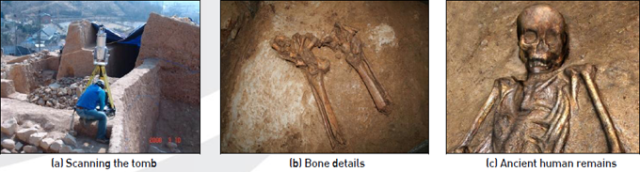
The GNRICH research team first scanned the overall shape of the tomb using a long-range outdoor scanner (the RIEGL LMS-Z390i). Then, to get close up and capture the high detail they needed on some of the human remains, they scanned a number of the bones with a Konica Minolta VIVID 910. These 3D scanners recorded all the spatial information and detailed 3D data that they needed, but this process combined for a total of 3.7 Gigabytes of data, a huge amount by any standard!
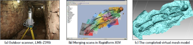
The team found that Geomagic Control X was the only software able to handle massive amounts of scan data with relative ease on their existing computers. Control X also provided them with sophisticated but simple tools to align, merge, and significantly reduce the size of the data without sacrificing scan quality or resolution. The researchers were even able to bring it all together into a common 3D coordinate system to create an exact and complete 3D virtual model of the bones in the tomb.
The GNRICH researchers were able to make many scientific conclusions from the 3D scan data they processed through Geomagic Control X. After processing they used Control X to analyze the resulting data, measuring features like the volume, length, and anatomical structures of the four corpses in the tomb. Through these analyses and other techniques such as carbon dating and mitochondrial DNA (mtDNA) sequencing, the researchers were able to estimate all kinds of data such as the height, weight, age, heredity, and dietary habits of each of the buried men and women. They were even able to perform forensic analyses on the ancient bodies, concluding that the tomb’s occupants may have been killed by poison or suffocation. Remarkably, they also found evidence of Soon-jang, an ancient burial custom in which servants were buried alive with their dead masters.
Finally, the GNRICH research team used Geomagic Control X and Geomagic Design X software to prepare their 3D scan data for production as physical 3D models. These models were made from 108 different resins to closely match the physical properties of bone and to aid in further study. In 2009, the team plans to continue their investigation into causes of death, diseases, athletic abilities, and more. They also plan to make whole body models using an innovative technology to add artificial muscle and skin to their resin bone models. The team is very excited about the power that 3D scanning and technology from 3D Systems have contributed to their efforts.
Product: SLA Printing
Industry: Consumer Products and Retail
Anyone who has opened a box of crackers to find the contents reduced to broken bits and pieces knows firsthand the consequences of poor packaging. Carman’s, an Australian food company passionate about only using the best ingredients, is mindful of how it delivers its products to consumers to ensure a high quality experience before the first bite is ever taken. Therefore, when Carman’s launched its new Super Seed & Grain Crackers, the food company kept presentation and preservation top of mind, and enlisted Birdstone, an Australian packaging design agency, to design an engaging tray insert. Due to the various requirements they needed to balance, multiple prototypes were required to demonstrate the proposed designs both aesthetically and functionally.

The packaging considerations in play for Carman’s were multifaceted: it needed to be easy to open, functional as a serving vessel, and enable Carman’s customers to reclose the container for storage. For ease of access, it was determined that the crackers should be stacked in three columns with room to encase the top crackers without crushing them, but also be easy to fill to not disrupt the production line. Lastly, the packaging needed to meet the retailer requirement for vertical packaging to maximize differentiation on the shelves. There was also a question of on-shelf instability due to the light weight of the product and the properties of the tray material.
Birdstone knew that arriving at the correct design would require accurate prototypes, and therefore reached out to 3D Systems On Demand Manufacturing due to previous successful collaborations.
Birdstone worked closely with Carman’s marketing and product development teams as well as its packaging supplier to review and narrow the packaging design concepts to two. From the outset, the top priority was to maintain supply chain efficiency throughout packaging manufacturing and product filling, followed closely by building brand equity into the tray with an effective and hassle-free customer experience. Relaying this information to 3D Systems On Demand Manufacturing, Birdstone and the 3D printing service bureau talked about the requirements for the prototypes.
Due to the complexity of the casing designs and unique functional requirements involved, 3D Systems’ On Demand Manufacturing experts helped Birdstone select the most suitable prototyping process, materials, and finishing process to meet its outlined requirements. Using Stereolithography (SLA) 3D printing on 3D Systems ProX® 800 machine, 3D Systems built both a one- and two-piece prototype in Accura® ClearVue™, a rigid and tough clear 3D plastic material offering the highest clarity and transparency on the market.
In just four days, the SLA prototypes were printed and finished to meet Birdstone’s quality and realism requirements. 3D Systems’ On Demand Manufacturing experts followed the premium finishing protocol for Accura ClearVue to deliver water-clear prototypes through a process of wet and dry sanding followed by clear coating. These prototypes were then submitted for manufacturing tests and consumer research to validate and rate the success of each concept, and to assess the performance and limitations of each packaging option at all critical touch points.

At this stage, Birdstone ordered four copies of the leading packaging design from 3D Systems On Demand Manufacturing, which were created using 3D Systems’ cast urethane process. The preferred SLA prototype was used to make a mold which was then used to cast additional water-clear copies using polyurethane, a material very close to what would be used for the final product.
Following full evaluation of the clear prototypes, the final design was officially selected: an attractive one-piece clamshell case, uniquely contoured to the shape of the stacked biscuits. According to Grant Davies, Director, Design & Strategy at Birdstone, “The final design plays to the strengths of the packaging material and provides a secure, re-useable home for the crackers throughout the supply chain and into the customers’ hands. It is functional enough to be filled, stylish enough to serve from, and securely re-closeable for on-the-go snacking.” Birdstone says that by adding another level of consumer engagement through functional and aesthetic packaging, Carman’s is able to offer a deeper brand experience beyond consumption.
Carman’s exciting range of crackers has forged a new place in the market for the company, and the tray has earned it many fans through the cleverness and convenience of its design. Birdstone says it is delighted to have contributed to a successful final product for its client, and to answer the unique challenges of the project within a tight deadline. “As usual,” says Davies, “3D Systems On Demand Manufacturing was a wonderful partner and worked with us to provide the most effective and appealing concept prototypes within the project budget.”
Birdstone’s packaging insert for Carman’s Super Seed & Grain Crackers was a 2018 finalist in the Packaging & Processing Innovation & Design Awards.
Product: Artec Space Spider
Industry: Design and Art
One of the most iconic scenes depicted in a dinosaur exhibit has to be the Stegosaurus and Allosaurus facing off in the Denver Museum of Nature & Science. The 26-foot-long Stegosaurus represents Colorado’s State Dinosaur. Not just the species of dinosaur, but the individual specimen that was adopted to represent the state. Stegosaurus was a herbivorous dinosaur weighing up to 10 tons that inhabited the area now called Colorado 150 million years ago. What makes this particular Stegosaurus so special is not the fact that it was found in Cañon City, Colorado, or even that it was mostly complete, a very rare thing for dinosaur skeletons. It was found by a class of high school students on a fossil-hunting field trip in 1936, and the teacher of that class of students, Frederick Carl Kessler, was able to arrange for his students to work alongside professional paleontologists to excavate the fossil skeleton.

Enter Mike Triebold of Triebold Paleontology, Inc. (TPI) in Woodland Park, Colorado. TPI restores and mounts fossil skeletons and creates skeleton casts, supplying them to museums across the globe. The company’s clients include the American Museum of Natural History in New York, Carnegie Museum in Pittsburgh, and the Smithsonian Museum of Natural History in Washington, D.C. The TPI headquarters house a collection of casts and original fossil specimens, which are on exhibit at the company’s hands-on natural history museum, the Rocky Mountain Dinosaur Resource Center.
Mike Triebold was looking to add a Stegosaurus to his catalog of casts, but not just any Stegosaurus. He was focused on getting the famous Kessler Stegosaurus at the Denver Museum for the project if at all possible because the new Royal Gorge Dinosaur Experience in Canon City was being built and they wanted a copy of the Stegosaurus that was collected by Kessler near Canon City. RGDE owner Zach Reynolds’ grandfather regularly accompanied Kessler on dinosaur digs from the 40s through the 60s, so the Stegosaurus has both family and community ties.
Reproducing this specimen was complicated by a couple of factors. One is the size of the specimen. Not only is this dinosaur over 26 feet long, but with the tall plates lining its neck, back and tail, it is also over 9 feet tall. Normally the size would not be an insurmountable challenge as each individual bone would just be molded in silicone and cast from liquid plastics. This specimen is not just bones on shelves though. It was mounted and placed on exhibit in the 1990s using purely permanent means, so it was not built to ever be taken apart. Steel was shaped around the skeleton, welded in place, and permanently puttied to the bones, so molding the individual bones in silicone was rendered impossible.
To recreate this specimen TPI’s Matt Christopher needed to mold it using 3D scanning. “We needed to three-dimensionally digitize the skeleton that could not be dismantled so that a replica could be 3D printed,” says Matt. “The dimensions and surface details needed to be close enough to what we would get from a silicone mold so that we could hand-finish 3D prints to look exactly like the original specimen.”

TPI used Artec Spider structured-light 3D scanner along with Artec Studio 3D scanning and processing software for the job. The scanner was supplied by Artec’s local partner 3D Printing Colorado. “Our Artec Spider captured exactly what we needed,” says Matt.
Spider was used to scan individual bones and regions of the skeleton as individual projects in Artec Studio. “This involved crawling inside the rib cage (yes, a full-grown person fits inside the rib cage of Stegosaurus) to capture the dorsal vertebrae forming the dinosaur’s back and the medial surfaces of the rib cage, shoulder blades, and hips,” says Matt. “There were also some interesting poses taken atop a step ladder to reach the tops of the big fan-shaped plates on the dinosaur’s back. We were able to capture all of the elements we needed, from the tip of the nose to the huge spikes at the end of the tail.”
The team ended up with 629 individual scans across 71 individual scan projects in Artec Studio. The number could have been higher, but in order to save time it was decided to skip scanning the elements that could be mirror-imaged to generate the other side, like the arms, legs and ribs.
Each scan needed to be aligned, cropped, and converted to 3D mesh files in Artec Studio. “The alignment features in Artec Studio were absolutely paramount to the success of this project,” says Matt. “Aligning each scan was as simple as manually orienting to a loose approximation of the correct position and letting the alignment tool refine the fit to perfection. Using Artec Studio to create and control the mesh generated from the aligned scans allowed us to extract the exact level of detail we wanted for manipulating and 3D printing.”
Exported meshes were free of artifacts thanks to a filter in Artec Studio that removes all elements smaller than the master scan. Small holes were automatically filled using the hole filling algorithm in Artec Studio. “Had we been scanning individual, unmounted bones, it would have been easy to generate complete, watertight meshes directly out of Artec Studio that would have required no additional post processing” says Matt. “With the steel armature remaining to be removed and the obstructed surfaces left to be reconstructed, watertight meshes were not really an option or a necessity for remaking the Stegosaurus.”
The resulting meshes were imported into ZBrush for separation of articulated elements, reconstruction of surfaces that were impossible to reach with the 3D scanner, like the spaces between articulated bones, and removal of the steel armature that obscured some bone surfaces.
TPI has a variety of 3D printers at their disposal ranging from a small Formlabs Form2 SLA desktop unit to a large-format Atlas from Titan Robotics. With numerous printers working on the project, printing the skeleton required six months. As the prints were finished, they were lightly resurfaced by hand and prepared for molding by adding mockups for internal steel armature and articulating some specimens to be molded in sections rather than as individual bones. Each completed bone or assembly is called a master. These masters were then molded in silicone rubber using high quality liquid silicone rubbers in two-part to multiple-part molds; something TPI staff has been doing for nearly 30 years.
The finished molds were then fitted with internal steel to be surrounded by plastic resins in the casting process. “The plastic is poured around the steel, so no external armature that would hide bone surfaces is needed,” says Mike. “With the casts poured around the armature, we can assemble the skeleton in any one of an infinite number of poses and weld together the steel protruding from inside each plastic cast. The mounted skeleton is then ready for hand-painting and delivery.”
With the project now completed, it will be on permanent display at the Royal Gorge Dinosaur Experience ( www.dinoxp.com ) in Canon City, Colorado, being unveiled on Saturday, May 19th. Zach Reynolds, his family and dad Dave will now be able to share the fulfilment of this important wish with the public for years to come.
According to Mike, this project would have been impossible to complete a couple of decades ago. “With our Artec Spider we were able to marry the best technologies of today with the most advanced traditional methods of molding and casting to create an exact copy of that great dinosaur without even touching it,” he says. “Now, how about that Allosaurus…”