Product: CJP Print Industry: Automotive and Transportation
“3D printing has become my one of my routines,” says Lee. “It is very attractive technology that allows us to print whatever idea we have in mind, and produce it in full color.”
“3D Printing Has Become My One Of My Routines,” Says Lee. “It Is Very Attractive Technology That Allows Us To Print Whatever Idea We Have In Mind, And Produce It In Full Color.”
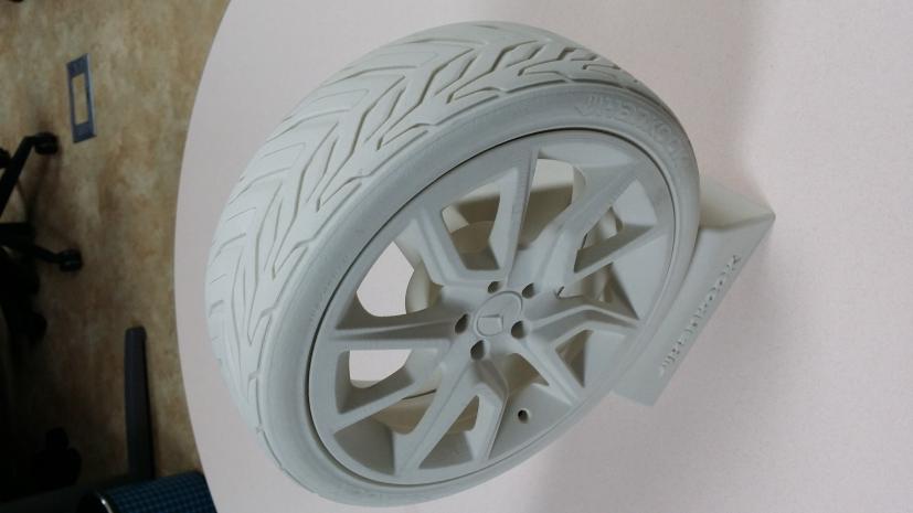
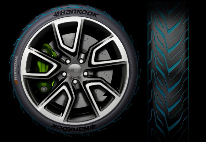
The design department at Hankook Tire uses a ProJet CJP 660 3D printer by 3D Systems as a key part of its concept design process. 3D printing technology has helped the design team deliver better communication between departments, save on costs, and improve design data security.
Founded in 1941, Korea’s Hankook Tire is currently both the seventh-largest tire manufacturer in the world and one of the fastest growing. Now selling in 185 countries worldwide, the company has developed a reputation for high-quality tires at reasonable prices. But the tire industry comes with intense competition, and Hankook takes design and development of new products seriously. As part of their commitment to provide top-notch tires, Hankook looks for the best ways to enable rapid development and testing of innovative tire designs while keeping those in-progress designs secret.
With this in mind, the company invested in a 3D Systems ProJet® CJP 660, a 3D printer that uses ColorJet technology (CJP) to create perfect full-color models that can be assessed for form and function.
Myungjoong Lee, CAD professional in Hankook Tire’s design department, prints a tire design in the ProJet 660 before he leaves at the end of the day, and the final model will be waiting for him when he gets to work next morning. With the size of the models being created, it takes about seven to eight hours to build a finished mockup model overnight.
Product: Artec Leo, Geomagic Design X Industry: Industrial Machinery and Heavy Equipment
At first, the task sounds straightforward enough: To replace a pipe. Add to that the fact that said pipe is 15 meters high, in an offshore vessel and surrounded by other pipes and equipment in a room 18 meters high and 10 meters long and three meters wide, and the complexity of the task starts to show.
The challenge facing Singapore’s Asian Sealand Offshore and Marine (ASOM) who had been tasked with this responsibility onboard the vessel, was how to execute the repair in such a confined and congested space. The nature of the room meant that there would be limited access, and a risk of causing damage to other vital equipment. The procedure needed to be fail-safe.
To get this complex task started, ASOM and Artec 3D’s Gold Certified Partner Shonan Design combined their engineering expertise and technology to resolve this critical problem. Another factor to consider was that all scanning needed to take place entirely on-site. (Spoiler Alert: The handheld Artec Leo’s on-screen real-time display would soon come in very handy.)
“The first step was using Artec Ray, a long-range LiDAR scanner, to capture the geometry of the room and an adjacent room to determine the space and sequencing of the removal and the replacement maneuver,” says Shonan Design’s Chief Application Engineer Lee Siow Hoe.
Able to scan from distances up to 110 meters away, Artec Ray is the fastest and most accurate 3D scanner. It is designed for submillimeter distance precision, which makes it perfect for large objects and long distances. Ray’s laser technology works excellently with ship propellers, airplanes, and buildings. With best-in-class angular accuracy, the data Ray captures is cleaner than other scanners, and its noise levels are kept to a minimum. Besides quick scans, this also makes processing faster and easier.
Artec Ray was set up in nine different locations on the few available flat surfaces around the room, such as staircase landings. For the Ray scan, the tight spaces in the room prevented placement of enough manual targets. To make targets effective, visibility is key and acute angles are discouraged – this was no problem for Ray, which is able to scan and align without targets.
“No checkerboard or sphere targets were used for the Ray scans registration,” Lee explains. “A one-click registration in Artec Studio 14 was enough to auto-align all the Ray scans, based on surface geometries within each scan. This simplified the job greatly.”
The restricted space provided a challenge in the creation of a complete 3D map, but the work was only just beginning. On top of the full Ray scan, a high-quality 3D scan from Artec Leo was needed. The Leo scan would also be able to ‘zoom in’ and capture the details necessary for fabricating the replacement pipe, and to scan any obstructed areas.
Because the pipe is vertical, and given the layout of the room, there weren’t many places to stand with handheld scanners. Instead, two brave team members qualified in rope access techniques were trained in scanning and safety, harnessed with lengths of rope, and were soon rappelling down the vertical pipe spool – rope in one hand, Leo in the other.
If this sounds like a job for seasoned scanners with years of experience, think again: The two rapellers were recently trained in using Artec Leo. The training proved to be straightforward, a tribute to the user-friendly design of the Leo.
“Leo scanners are fast, and with automated alignment, it was easy to resume scanning from where we left off,” a member of the ASOM scanning team said.
If ever there were tasks made for Artec Leo, this would be among them: With onboard automatic processing, the men scanning were able to see the scans being created in real time even without a computer present. Leo’s touchscreen panel also allows the user to zoom in and see if everything has been properly captured – and if it hadn’t, to revisit any areas that the user might have missed. This feature proves especially useful for first-time users in an unfamiliar setting.
The practical training given to the ASOM employees involved practicing on whatever they could adopt as suitable targets – the staircase and common pipe areas, for example. “Familiarity with the equipment was crucial for the job to be successful given the challenges posed”, says ASOM Director Simon Ng.
With a highly accurate scan of the entire room provided by Artec Ray and a focused, detailed scan of the pipe available via Artec Leo, the team had everything they needed. Superimposing data from the Leo scan on the Ray scan, a final global registration ensured that the Leo data fit perfectly with the Ray data.
“The Leo raw data was aligned and processed using the Ray pipe scan as a backbone, so that the entire 15 meter length of the Leo scan had minimum accumulation of error,” Lee says.
With the 15-meter pipe scan processed, the next step was to translate the digital 3D scan data into an accurate 2D isometric drawing to fabricate a replacement.
This was achieved using the Pipe Wizard feature in Geomagic Design X, and some modifications to the original design to facilitate installation were made and incorporated into the 2D drawing.
The scanning project was completed in two days with an onboard team of four people during which the FPSO continued to operate.
“The combination of the handheld Artec Leo and the standalone unit Artec Ray made a very big difference. We managed to capture all the necessary details this way,” says Ng.
“From the detailed planning and execution, I believe we managed to get fantastic results from the scanning and modeling,” Lee adds.
Product: Teamcenter Industry: Automotive and Transportation
Teamcenter and Tecnomatix enable Chery to increase efficiency and improve quality in research and development
Founded on January 8, 1997, Chery Automobile Co., Ltd. (Chery) is one of the leading manufacturers of autonomous car brands in China, growing through independent innovations after the reform and opening of the market in China. Over the past 20 years, Chery has built a series of renowned brands such as Arrizo, Tiggo, QQ, and Fulwin, and exported products to more than 80 countries and regions, thus becoming a beacon of independent innovation. In addition, Chery also owns such international brands as Qoros, Jaguar and Land Rover through two affiliated joint ventures. So far, Chery has achieved cumulative sales of over six million units, making the company the first passenger vehicle manufacturer in China to surpass that number, which includes cumulative exports of over 1.25 million units. Chery has led in exports of Chinese passenger vehicles for 14 years in a row. Since its founding, Chery has attached great importance to exploring both international and domestic markets and has actively implemented the “going out” strategy, thus becoming China’s first automaker to export vehicles, complete knock-downs (CKDs), engines, automobile manufacturing technologies and equipment to foreign countries. Chery has built 14 manufacturing bases in Wuhu, Dalian, Ordos and Changshu in China as well as in foreign countries such as Brazil, Iran, Venezuela and Russia. In the evaluation of “Top 20 in Chinese Enterprises’ Overseas Performance Survey” organized by the China International Publishing Group under the guidance of the State Council Information Office of the People’s Republic of China, Chery was honored as the “Chinese Enterprise with the Best Overseas Performance” both in 2015 and 2016, and was ranked the number one player in the equipment manufacturing industry for two consecutive years.
Driven by innovation
“Independent innovation” is the core of Chery’s development strategy. Since Chery’s founding, the company has adhered to independent innovation and endeavored to become a technology-oriented enterprise, investing five to ten percent of its annual turnover in new product development. Based on the V-shaped development system, Chery has formed a collaborative, bigger-picture research and development (R&D) layout integrating the development talents and processes of Qoros, Jaguar and Land Rover, and a complete R&D system that integrates development, trial manufacturing and testing of vehicles, powertrains and key parts, centering on the Automotive Engineering and Research Institute in Wuhu and powered by Chery Technical Center Shanghai.
Through independent innovation, Chery has achieved breakthroughs in an array of core technologies such as dual variable valve timing (DVVT), turbocharged gasoline direct injection (TGDI), continuously variable transmission (CVT), new energy and intelligent technology that drive the technical upgrading of all series. By the end of 2016, Chery had applied for 14,316 patents and won 9,155. As China’s largest exporter of passenger vehicles, Chery is actively competing in the international market and trying to keep pace with international standards of product design, development and manufacturing to achieve parity with world-class brands. The company has observed over the years that in the course of developing advanced technologies, Chinese automakers need reliable long-term partners like Siemens Digital Industries Software, a specialist in product lifecycle management (PLM) soft-ware solutions.
Strong alliance
The partnership between Chery Automobile and Siemens Digital Industries Software began in 2003. With the use of NX™ soft-ware, Chery was able to realize advanced digital product design. In addition, the R&D team used NX solutions to perform virtual simulation and verification of digital prototypes. This approach improved design efficiency and quality while reducing inspection costs. Over the years of cooperation between Chery and Siemens Digital Industries Software, Chery has even established its own information technology company to promote product lifecycle digitalization and computerization through-out the industry. Here, PLM functions and other solutions are planned, implemented and promoted. The PLM implementation team includes engineers, computer scientists and Siemens Digital Industries Software experts.
Teamcenter promotes R&D collaboration
To further support Chery’s integrated R&D management approach, the company selected and deployed Teamcenter® software for digital lifecycle management following the successful implementation of NX. As a result, Chery standardized its R&D process and now centrally manages all development projects, personnel and data. The PLM project director at Chery says, “Teamcenter has helped us to re-use design knowledge and enhanced design team collaboration. Product configuration management and engineering changes have become more efficient and accurate thanks to strict project management and reliable data flow.” “With Teamcenter, we were able to identify many points that had to be improved,” an engineer from Chery’s PLM project team says. “The PLM system supports design collaboration and enables design information sharing, data consistency and re-use of design knowledge and data. In terms of design changes, we discovered early development issues and were able to reduce engineering changes and implementation times. In addition, the PLM system has enabled enhanced collaboration between research and development centers. This eliminates typical cross-nation and cross-region issues, such as inefficiency, inaccuracy and poor communication, and drives business development forward.”
Teamcenter supports Chery in the realization of standardized management of its product development process. Since implementation, the company manages product coding rules, drawing templates, design changes and data sharing modes on a central PLM platform. Such a highly stan-dardized process advances product development quality, drives collaborative design and promotes communication and project collaboration. Thanks to excellent cooperation between Chery’s PLM project team and the Siemens Digital Industries Software team, Teamcenter was quickly connected to the existing enterprise resource planning (ERP) system, enabling the exchange of product development and manufacturing resources management information. This brought the comprehensive information management of Chery to a higher level.
Tecnomatix supports improvement of manufacturing quality
Today, the auto market is flooded with car brands and models and competition is increasingly fierce. Poor-quality products are not recognized and accepted by consumers. Chery uses many opportunities for quality improvement and stabilization. An engineer from the dimensional control section at Chery Automobile Manufacturing Engineering Institute notes: “In recent years, we have initiated a series of quality control procedures, such as the improvement of processes and standards, the consistent control of project milestones and the addition of test equipment and tools.” Essential quality operations include the dimensioning of product parts from structural analysis to process selection, product and process design verification, piloting, vehicle experimentation, production preparation, process review and control; the use of post-production test tools; and data analysis and feedback. With the Tecnomatix™ portfolio of digital manufacturing solutions, the dimensional engineering team can intervene at the development stage, based on the digital prototype, to analyze structure, positioning, assembly processes, and other factors. On the basis of the results, the team can make suggestions as to how structures and processes can be optimized and identify possibilities for improving body alignment and product quality.
The introduction of Tecnomatix has significantly expanded the dimensional analysis capabilities for Chery’s engineering team. The original dimensional analysis method was a chain calculation formula based on 2D data and was relatively inaccurate. Tecnomatix offers powerful dimensional analysis tools to conduct virtual simulations of manufacturing and assembly processes, predicting deviations and identifying causes. “Synchronization of the Tecnomatix solution with dimensional engineering improves Chery’s capability to predict problems before production,” says a dimensional control engineer at Chery. “For example, in their analyses, they have identified positioning and assembly problems of headlights, thus saving a huge amount of tool modification costs and avoiding production delays. Dimensional engineering provides engineers with product design, process, manufacturing, tooling, and quality control utilizing a quality management collaboration platform that can help solve problems, minimize time and reduce costs at the early stages of development. Chery’s dimensional engineering is already in process for high-end models, with plans to cover all models in the future.”
Joining hands with international partners
Building an international brand is Chery’s strategic goal. Chery has been advancing its globalization layout and accelerating the transformation from the “going out” of products, “going in” of technologies and plants, to “going up” of the brands. In the meantime, Chery keeps deepening overseas cooperation by implementing the product strategy, localization strategy and talent strategy, so as to build Chery into a world-renowned brand with global influence.
Chery has established nearly 1,500 distribution and service outlets, and formed business areas with Iran, Brazil, the Middle East and Latin America at the core, with presence in over 80 countries and regions across the world. Chery has a three-step internationalization strategy: before and through 2013, it was at the stage of exploration and market development; from 2014 to 2020 marks the stage of market expansion, with the aim of building an international brand with quality products and services through overseas plants and overseas marketing. After 2020, the company will be entering the stage of global operation, to build an automotive brand with international influence using world-class products and more professional services.
In the course of internationalization, Chery also needs partners with experience in the international automotive industry. This is one of the main reasons for selecting Siemens Digital Industries Software as its partner. The PLM project director at Chery says: “We chose Siemens Digital Industries Software solutions because the company has a wealth of experience in the international auto industry and the software is widely used by both OEMs and suppliers. The use of Teamcenter and Tecnomatix enables us to align our research and development work with international standards. The experience of Siemens Digital Industries Software in the automotive industry supports us in integrating advanced design management methods and technologies and in realizing our global development strategy.”
“Siemens subsidiaries and professional service teams all over the world also play a special role in the establishment of Chery’s global research and development and manufacturing sites,” Chery’s PLM project director adds. “The Siemens Digital Industries Software team in North America has a wealth of experience in vehicle analysis and is therefore an indispensable part of Chery’s dimensional engineering project.”
Chery is very optimistic about the long-term collaboration between Chery and Siemens Digital Industries Software. “Since the implementation of the PLM system, Chery has significantly increased its market share and customer satisfaction has notably improved,” the PLM project leader says. “Currently, we are working together with Siemens Digital Industries Software subject matter experts on deployment of the bill of materials project. Our expectations for this project are very high. After successful implementation, it will further enhance Chery’s market advantages.”
Product: Teamcenter Industry: Industrial Machinery and Heavy Equipment
Sparkonix implements PDM quickly to help designers significantly decrease time spent searching for storing and retrieving data
Corralling data
Sparkonix India Private Limited (Sparkonix), which was established in 1968, is a leading manufacturer and exporter of electrical discharge machining (EDM) equipment. The company also produces special-purpose EDM drill machines and metal arc disintegrators, which are used to remove broken taps and drills. Furthermore, the company engineers a range of innovative solutions in steel rebar branding and handling, and construction technologies.
Sparkonix machines typically include hundreds of parts, from fabricated and machined parts to castings, sheet metal, electronics and electrical items mounted directly on mechanical assemblies. Its market is the die and mold industry and special purpose machine (SPM) and special purpose drill (SPD) EDM operators.
Sparkonix uses Solid Edge® software from product lifecycle management (PLM) specialist Siemens Digital Industries Software for computer-aided design (CAD). However, the company was finding it difficult to manage a rapidly expanding amount of design data.
“The amount of CAD data was growing and we needed to manage it better so that no unnecessary duplicates would be created,” says Anand Atole, assistant manager of Design at Sparkonix. “Being able to re-use design data to speed up work was a priority. Also, the number of users accessing data was increasing and we required control of user workflow, so we needed revision management.”
Speeding up the process
Sparkonix is in a highly competitive market, so the company needed to come up with new concepts and designs. The company was intent on improving its existing products and processes without compromising quality. Achieving this while keeping costs in mind was a big challenge, as was meeting deadlines for deliveries of customer orders and providing updates to marketing on changes to designs.
With these challenges delaying the design-to-delivery process, the company knew it needed a solution that would enable it to move significantly faster, especially with customer demand continually increasing.
Sparkonix previously had a central location for data, but it could not be easily searched. Equally frustrating, Sparkonix was unable to reuse the data. In addition, it was hard to avoid creating duplicate data, and anybody could access it. What Sparkonix wanted was total control of its design data, with ease of access, the ability to readily re-use the data and strong security.
Streamlining design data
Sparkonix found the answer to its information management challenges in Siemens Digital Industries Software’s Teamcenter® software Rapid Start configuration.
“By choosing Teamcenter Rapid Start, we have a central repository for design data with strong management capabilities,” says Anand. “We can search our database for required information to use and re-use parts and assemblies.
“Now we are able to efficiently manage product revisions. We can control the access rights to data based on user type, and share updated data easily and immediately. As a result, we have moved to more controlled paperless operations for the design department. Earlier, we had to do manual paperwork to maintain data that is now being handled by our PDM software,” says Anand. Currently, Sparkonix is using Teamcenter Rapid Start to provide design data to purchasing, sales and support. People can view documents and designs in Teamcenter Rapid Start, because the embedded visualization capabilities present designs in CAD-neutral JT format for viewing and markup. Stakeholders don’t need access to CAD applications to collab-orate and get the information they need to make the right product decisions.
“Ultimately, Teamcenter Rapid Start has enabled us to streamline design data and make it available to all for reuse, from design to sales and support. Designers can now concentrate on design rather than on storing, searching for and retrieving data. We have reduced design time by 25 percent.”
Getting into production quickly
Sparkonix opted for Teamcenter Rapid Start because it wanted to get up and running quickly and immediately apply PDM best practices for data and process management. What’s more, the company wanted an affordable option suited to its small business profile.
Teamcenter Rapid Start provided the PDM capabilities Sparkonix needed at a compel-ling price, while giving the company the option to grow into a full-scale PLM implementation at any time. Because Teamcenter Rapid Start is a preconfiguration of Teamcenter, Sparkonix can extend its implementation to PLM while retaining the preconfigured menu options and processes for PDM.
Following the standard PDM deployment methodology and best practices, Sparkonix implemented Teamcenter Rapid Start in just four weeks, taking two days to train its users. The company can easily upgrade with each future release, noting that it takes minimal information technology (IT) expertise to support and maintain the system.
Trimming inventory
Among a long list of examples that demonstrates the software’s advantages, the company is using Teamcenter Rapid Start for the pipes its uses to connect pumps and filters. “With Teamcenter Rapid Start, we are able to get an idea about the different sizes of pipes that are being used,” says Anand. “Then we can decide to limit variations of pipe lengths and settled on some common sizes, so now we avoid maintaining excess inventory.”
Using the preconfigured processes in Rapid Start – such as design review, supplier design exchange and change management workflow – Sparkonix can streamline and better track project status.
Utilizing support
From the start, Sparkonix had the support it needed to succeed. “Our software partner helped at each stage of the implementation process to get us working quickly and effectively,” says Anand. He notes, “Siemens Digital Industries Software’s Global Technical Access Center (GTAC) is always there to help us out with any matter in which we desire assistance.”
Product: Femap, Simcenter Industry: Consumer Products and Retail
With Simcenter Femap, company increases re-use of proven designs, boosting productivity and decreasing costs.
The need for virtual prototypes
In the offshore industry, operational certainty is one of the most important requirements. The installations are large and the investments are high. Virtually everything is unique and leaves little room for error. As a supplier of tools for the installation of offshore equipment, IHC Handling Systems v.o.f. (IHC Handling Systems) is very familiar with the market. Functionality and quality must be validated prior to production. Virtual prototypes are the only way to ensure this.
IHC Handling Systems is part of IHC Merwede, a world leader in the dredging and offshore industry. IHC Merwede’s products include dredging vessels, equipment and components, as well special-purpose vessels and technology. IHC Handling Systems focuses on products for oil, gas and wind, such as equipment for pipe laying, equipment for the installation of oil and gas rigs and equipment for the installation of offshore wind mills.
Quick response and communication
In order to lay pipelines on the seabed or put piles of windmills upright, the thin-wall, tubular pipes need to be picked up by grippers. These are metal clamps that are placed on the inside and outside of the tube. The force with which the clamps grip the steel enables the lifting of the product. For the leveling of oil rigs, IHC Handling Systems provides equipment to establish a temporary connection between the seabed construction and the jackets on which the platform rests. Most of the products produced are project-specific. IHC Handling Systems usually has an early involvement in new offshore projects. “Customers approach us because of our reputation and experience,” says Cor Belder, concept engineer at IHC Handling Systems. It is important to have certainty about the concept solution in an early stage. A quick response to customer demands and communication are essential. “At the same time, we also want to offer functional certainty. That can only be achieved using advanced and integrated design tools.”
Lower cost of software
A few years ago, IHC Handling Systems purchased licenses of Siemens Digital Industries Software’s Solid Edge® software, a comprehensive hybrid 2D/3D computer-aided design (CAD) system, and Algor® Simulation software (which is currently owned by Autodesk and is offered under the name Autodesk® Simulation Mechanical) for finite element analysis (FEA). Both solutions were bought through Bosch Engineering, a Siemens Digital Industries Software partner. “Together with a sister company in the IHC Merwede group, we were forerunners in using Solid Edge,” says Belder. “Algor worked nicely together with Solid Edge, and data transfer between the two applications allowed for quick analysis of design alternatives.” But in a recent reassessment of the computer-aided engineering (CAE) applications, Belder saw room for improvement, specifically in the areas of data integration, meshing and programming.
“Early on in the evaluation, we developed a preference for Simcenter Femap,” says Belder. “Simcenter Femap offers a significant improvement in functionality over Algor at lower software costs. We want to spend our time on the evaluation of alter-native designs and don’t want to lose it over issues related to data transfer. Simcenter Femap and Solid Edge are tightly integrated, which saves time and reduces risk.” Belder notes that in addition to the robust geometry exchange, the mesh is more constant and allows for better local refinement.
Fast iterations
In a typical project, the concept engineer develops new models or combines and re-uses existing ones. “Concepts are almost always modeled in Solid Edge,” says Belder. “In the early stages, these are simplified designs focused on functionality, but ready to be used in preliminary CAE analyzes. The integration of Simcenter Femap and Solid Edge allows for fast iterations in this concept phase.” These functional concept designs are also used for client communication.
IHC Handling Systems uses both the linear and the nonlinear functionality of the NX™ Nastran® software solver embedded in Simcenter Femap™ software. The linear functionality is used for all static calculations as well as for contact analysis. Contact analysis is often used for designing lifting tools, where steel friction pads are pressed on the inside and outside of the pipe or pillar using hydraulic cylinders. The nonlinear analysis is used for the calculation of the friction between the steel pillar and the friction pads. This friction is the basis of the grip needed to lift the pillar or pipe. The amount of friction is defined by the pressure exerted on the cylinders. At the same time, the pressure should not lead to deformation of the pipe. “These are complex calculations taking up to 20 hours,” notes Belder. “We need to find the technical and economical optimum, in other words, the functionality must be ensured at the lowest cost possible. We take the calculations to the elasticity limit of the material.”
Re-use of proven designs
The re-use of meshes and load cases saves IHC Handling Systems a lot of time, especially in projects where existing concepts can be used, even though there may be many possible variations. An example is the upending tool that is used for lifting pillars. Upending tools must be able to handle many different diameter/wall thickness combinations and must be able to pick up pillars with diameters up to 6,000 millimeters. The customer specifies the diameter of the pillar and the lifting capacity of the available crane. To find the most economical solution, the engineer would traditionally select variants and perform the necessary calculations. This implies that, for every variant, the generation of the mesh and the application of the load case are required to perform a single calculation. The geometry of the variants differs too much to re-use the mesh and load case.
Using the programming capabilities of Simcenter Femap, the CAE model can be configured and generated automatically, for example, from Excel® spreadsheet software, including the mesh and the load case to be analyzed. Moreover, programming with Simcenter Femap is easy to learn. “Using the traditional way of working, we would be able to analyze only three combinations a day,” says Belder. “Programming in Simcenter Femap saves us a significant part of the time needed for modeling, meshing and applying the load case. The preparations can be reduced from hours to minutes. We can respond much quicker to changing customer requirements.” According to Belder, building the application of the upending tool took, all in all, no more than a week: “The investment has already paid for itself, because we always need to do calculations in projects for upending tools, which we use often in our projects.”
The goal to work better, faster and more cost-efficient using Simcenter Femap has been achieved. “We were satisfied with the engineering tools we had, but there is always room for improvement. Using Simcenter Femap allows us, better than ever before, to serve our customers with our experience and quality,” concludes Belder.
Product: DLP Print Industry: Electronics and Semiconductors
The sudden and alarming global rise of COVID-19 has highlighted the importance of accessible and rapid disease detection. The ability to test for disease not only enables better containment to prevent further spread, but enables epidemiologists to gather more information to better understand an otherwise invisible and mysterious threat. From revealing means of transmission to rates of infection, the criticality of testing for infectious diseases has now been felt worldwide.
A team of researchers at Imperial College London, led by Dr. Pantelis Georgiou, is tackling this problem head-on with a project called Lacewing for pathogen detection. Offering results within 20 minutes from a smartphone app synced to a cloud server, Lacewing makes disease testing portable, including SARD-CoV-2-RNA, and automates the tracking of disease progression through geotagging. It is a sophisticated “lab-on-a-chip” platform that promises to fill the access- and information-gaps in the world of diagnostics by combining molecular biology and state-of-the-art technology. Whereas other diagnostics technology requires large and expensive optical equipment, the electrical sensing method and small size of Lacewing is a true evolution in approach.
Key among the technologies behind Lacewing is 3D Systems Figure 4® Standalone 3D printer and biocompatible-capable, production-grade materials. Used for both prototyping and production of microfluidics and functional components, Imperial College PhD student and research assistant Matthew Cavuto says key Lacewing components were designed based on the capabilities he knew he had with Figure 4. “Microfluidics are a tricky thing, and fabrication has traditionally been done through slow, expensive, and labor intensive cleanroom processes,” says Cavuto. “With the Figure 4, we’re now able to rapidly print parts with complex internal 3D fluidic channels for transporting sample fluid to different sensing areas on the chip, greatly improving our microfluidic production capabilities.”
As critical as the design element is to this project, it is just one piece of a highly sophisticated solution. Beyond the part complexity and detail fidelity enabled by 3D Systems’ Figure 4, this 3D printing solution has helped the research team through print speed, print quality, and biocompatible material options.
Quick iterations to answer the need for COVID-19 testing
The Lacewing platform has been in development for a little over two years now, and is a molecular diagnostic test that works by identifying the DNA or RNA of a pathogen within a patient sample. This type of test makes it possible to determine not only if someone is infected with a certain disease (dengue, malaria, tuberculosis, COVID-19, etc.), but to what degree, which provides more insight into the severity of the symptoms.
Prior to the outbreak of COVID-19, the impetus for this test was to enable portable testing in remote areas of the world. Although portability is often taken for granted in a smartphone age, molecular diagnostics have traditionally required a large and expensive pieces of lab equipment. Lacewing has replaced the previous optical technique with an electrical one using microchips, and has been quickly prototyped, iterated, and produced using the Figure 4 Standalone and biocompatible materials. Each Lacewing microfluidic cartridge is roughly 30 mm x 6 mm x 5 mm, printed in 10-micron layers.
As the research team began adapting the test to answer the global testing needs of COVID-19, it started printing new designs almost daily. For this, Cavuto said the speed of the machine was a major benefit. “At one point, I was able to print and test three versions of a particular component in a single day with the Figure 4,” he says. This ability to rapidly iterate designs has removed the friction of trying something new, and the resulting experimentation and increased information gathering has led to improvements in the overall system. “We’ve easily gone through 30 versions in the last 2 months,” says Cavuto.
The team designs all its parts in SOLIDWORKS, and uses 3D Sprint® software to set up each build. 3D Sprint is an all-in-one software by 3D Systems for preparing, optimizing, and managing the 3D printing process, and it has been useful to the research team in finding and resolving unexpected issues. “Occasionally we’ll get an STL error that 3D Sprint can solve for us in the prepare tab,” says Cavuto.
Having worked with many different 3D printers in the past, Cavuto says Figure 4 is different because there are less barriers to printing in terms of time, cost, and quality. With other printers, he would question whether a print was worthwhile in terms of both time and material cost, whereas Figure 4 has removed that friction. “I print a part, and see if it works. If it doesn’t, I redesign and print again just a few hours later,” says Cavuto. “I’m able to iterate super quickly just because of how fast the printer is.”
Truly biocompatible materials do not inhibit chemical reaction
Despite the time pressures for rapid testing options, speed was not the most important factor for the research team. Because this application comes into direct contact with DNA, it is only possible with certain biocompatible materials.
The Imperial College team is using Figure 4® MED-AMB 10, a transparent amber material capable of meeting ISO 10993-5 & -10 standards for biocompatibility (cytotoxicity, sensitization and irritation)*, and that is sterilizable via autoclave. This material is used for the translucent microfluidic manifolds. “Figure 4 MED-AMB 10 has shown impressive biocompatibility for our PCR reactions,” says Cavuto. “A lot of materials we’ve tried in the past have inhibited them, but Figure 4 MED-AMB 10 has shown low interaction with our reaction chemistry.” This is critical to the entire project, as any interference by the production materials could delay or prevent the intended reaction from happening.
Using Figure 4’s diverse portfolio of materials
Not only is the team using Figure 4 MED-AMB 10 to print the microfluidic components for Lacewing, but they are also using Figure 4® PRO-BLK-10, a production-grade, rigid, heat-resistant material, for the device enclosure, and Figure 4® RUBBER-65A BLK, a newly released elastomeric material, for gaskets through the device. One part of Lacewing is even made from Figure 4® FLEX-BLK 20, a material with the look and feel of production polypropylene. Besides the electronics and some hardware, nearly the entire device is currently produced using the Figure 4 system.
Fully cleaned and post-processed in under 20 minutes
A clean and smooth surface is critical to the final functionality of the Lacewing cartridges. For this reason, the research team is foregoing any nesting or stacking capabilities of Figure 4 to print the cartridges in single layers. As the project is still in the design phase, the team has not yet fully loaded the build plate, but estimates a maximum build of approximately thirty microfluidic cartridges at a time.
Given the sensitivities of the application, post-processing is critical. Once printed, parts are washed in an IPA bath, cured, sanded, and washed again to ensure the parts are all free and clear of residue or sanding particles. “We want to avoid contamination at all costs,” says Cavuto. “Making sure the parts are clean and sterilized is important for a successful reaction and accurate diagnosis.”
In total, Cavuto estimates that post-processing takes under twenty minutes, and many parts can go through the process at once.
New capabilities for development and innovation
“Figure 4 has changed what I can print, or what I think I have the capability of creating,” says Cavuto. “In terms of resolution, speed, surface quality, range of materials, and biocompatibility, there’s nothing that compares to Figure 4, and I’ve probably used every type of 3D printer you can imagine.”
The Imperial College research team plans to have the COVID-19 test validated soon with the United Kingdom National Health Service (NHS), paving the way for scaled production within the next six months. For a complete look at how Lacewing works, explore this information page by the Imperial College research team.
Product: Geomagic Design X Industry: Industrial Machinery and Heavy Equipment
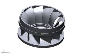
When small business owner Matthew Percival of 3D Rev Eng was contracted by Dependable Industries, a pattern and tooling shop in Vancouver, British Columbia, to assist in the reverse engineering of a power generation Francis Runner casting, the full power of Geomagic Design X was put to the test.
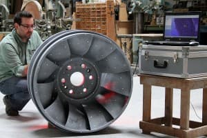
Percival had a very finite, one-day window of time to 3D scan the part. There was no drawing to confirm against, so he had to be able to work quickly and accurately. The working runner that was being reversed engineered was on its last repair cycle and needed to have a replacement casting ready in one year. The scan data was acquired in about four hours using a hand held scanner.
The deep narrow pockets of the hydraulic passages limited the scanner’s range and made complete data acquisition impossible. With about 85% of the part scanned, Percival knew he had enough to make a complete CAD model using the software from 3D Systems.
CAD model using the software from 3D Systems.
“For me, Design X is the obvious software choice. The ability to generate solid models directly on the scan data is priceless.”
-Matthew Percival of 3D Rev Eng
Using the data live on site, Percival was able to create sketches and smooth lofted surfaces between the two sides of the acquired data and conform it to the casting using hands on methods in Geomagic Design X. Doing this revealed a number of interesting details to the customer:
The center axis of the impeller was no longer square to the
vanes which results in an unbalanced and inefficient part
The cast surfaces were badly worn and out of typical tolerance
The volume of each cavity was inconsistent
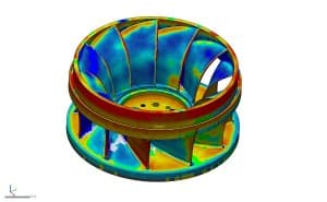
Design X easily overcame these issues. Percival was able to generate sketches on the blade, as well as an accurate smooth surface that he could revolve around the extracted revolution axis. The surface was then trimmed to match the profile and revolved to obtain the proper count of blades. Comparing this data live with color deviation maps to the scan data, Percival was able to ensure that accuracy was within the client’s requirements.
The problem of the part not being on the center axis was easily fixed, since Design X allowed Percival to redesign with design intent. He was able to model the part by extracting the profile, generating a sketch and adjusting the revolution axis to the proper design intent. Lastly, he merged the model and extracted the radii from the scan data, applying it to every blade. Once the model was complete in Design X, he used the software’s LiveTransfer technology to send the entire feature-based solid model into Solidworks and saved it as a native sldprt file for the client.
Cost savings in decreased downtime of hydro power generation plant
$ 20,000 per day *
Average cost to traditionally reverse engineer a runner
$ 3,800 and 4 days
3D Rev Eng cost
$ 2,500 and 2 days
Cost to manually produce foundry tooling from traditional reverse engineering data
$ 35,000 and 5 weeks
Cost to CNC cut foundry tooling from CAD data made in Geomagic Design X
$22,000 and 3 weeks
Cost savings in finish machining and balancing of a casting made from CNC tooling
$ 3,500
Cost savings and power generation efficiency resulting from highly-accurate hydraulic passages and balancing
UNLIMITED
Conclusion
The successful completion of the Francis Runner project has opened the door for other impeller projects for Percival and 3D Rev Eng. These projects include aquaculture impellers, mining impeller blades and Pelton wheels. Geomagic Design X allows Percival to quickly use complex shapes and surfaces to produce models within hours, which would otherwise have taken weeks.
3D printer delivers color, volume and quality to enable Starburns to create “thousands upon thousands” of faces for stop-motion puppets.
“Sad,” “beautiful,” “witty,” “every character fascinating and boldly realized”: These are not words one typically associates with a stop-motion film starring puppets.
But, then again, the film Anomalisa is something that’s not been seen before.
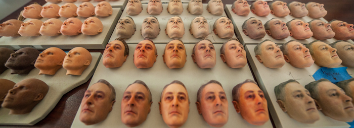
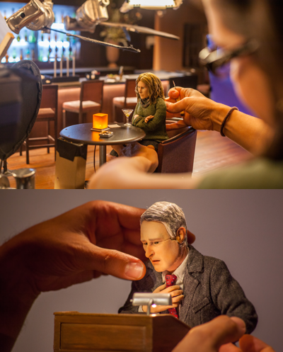
The range of expressive humanity achieved in the film was made possible by the high-resolution 3D color printing of the 3D Systems ProJet® CJP 660 system. Starburns Industries, a full-service production company based in Burbank, California, used the 3D printer to turn out thousands of different faces with life-like details such as wrinkles, smiles, frowns, worry lines and bags under the eyes.
Aesthetic Value Meets Productivity
Over the last few years, 3D printing has become commonplace in the movie industry for applications such as prototyping, prop making and creating objects that are difficult to construct in traditional ways. But, in the sheer volume of parts and in the emotional realm in which it is used, Anomalisa sets new precedents for 3D printing in entertainment.
Duke Johnson, co-director of Anomalisa, along with Charlie Kaufman (Being John Malkovich, Eternal Sunshine of the Spotless Mind), cited 3D printing for helping to establish the inner feelings of the characters and providing a higher level of detail. But for all the aesthetic value that the ProJet CJP 660 helped bring to the characters, the use of this particular 3D printer came down primarily to productivity: the system is fast, reliable and generates life-like color.
The ProJet CJP 660 outputs full-color 3D prints in one run without having to change palettes. Its build area of 254 x 381 x 203 mm (10 x 15 x 8 inches) enabled Starburns to turn out dozens of faces with different expressions in a single run within hours. “Color is the most important attribute for us, along with speed and the volume the machine can produce,” says Bryan LaFata, Operations Supervisor at Starburns Industries. “We were running the ProJet almost non-stop for a year and a half during Anomalisa production, creating thousands upon thousands of faces.”
Thousands of Expressions
Starburns modeled and printed three basic head designs for Anomalisa: One each for the lead characters Michael and Lisa, and another for what is called the “world face,” a composite face modeled from 20 or more Starburns employees. The world face was used for every character except Michael and Lisa.
The faces for the characters include an upper and lower faceplate. Thousands of expressions were modeled and printed by Starburns for the characters. This gave animators access to nearly every possible expression for a given scene. “We produced racks full of faces so they could be switched out at any time,” says LaFata. “It could take multiple facial models just to get the right smile.”
Retaining the Look and Feel
A conscious choice was made by the Anomalisa directors to keep the lines between the upper and lower faces in place without digital airbrushing.
James A. Fino, Executive Producer and Partner at Starburns, explains this decision in an article on the Producer’s Guild of America website: “Recent stop-motion animated features typically erase those lines digitally, but that was not our choice for Anomalisa. Rather than a distracting element, the seams serve as subtle and persistent signs of the incredible artistry on display in the film.”
In a New York Times article by Mekado Murphy, co-director Kaufman explained it this way: “We didn’t want to hide the fact that it’s stop-motion. We didn’t want to paint out the thing that it was…we wanted that feeling of the unseen presence of the animators.”
Starburns also did minimum post-processing of the characters’ faces, retaining the look and feel that came directly from the ProJet 660. Again, this was the directors’ preference.
“We used [3D printing] for a very specific purpose with the realism that they wanted in the faces, and the textures and the differences in color would not have been possible by hand-painting,” says Caroline Kastelic, Starburns Puppet Supervisor, in an IndieWire interview. “And that’s why they have that nice texture on them…I find that aesthetically brilliant and it also saved us a lot of time.”
Local Support
Creating the thousands of faces, dozens of body models, and the realistic sets for a production such as Anomalisa takes teamwork; not just among the nearly 200 people at Starburns, but by outside partners as well.
LaFata gives credit to 3D Rapid Prototyping, a 3D Systems partner based in nearby Garden Grove, California, for keeping Starburns supplied with materials and even printing face models when needed.
“We were pushing out a lot of faces, often 24/7, and Bill Craig [3D Rapid Prototyping President/CFO] and his team were always there to help us out,” he says.
Big Future for 3D Printing
No matter how fascinating the behind-the-scenes technology is for a film, the ultimate measure of success is how the story is delivered. In the case of Anomalisa, 3D printing is not just a special effect or quirky conversation piece; it is integral to the way the characters perform.
The approach seemed to have struck a chord: Beyond Oscar and Golden Globe nominations, Anomalisa was the first animated film to win the Grand Jury Prize at the 72nd Venice International Film Festival. In his five-star review in Rolling Stone magazine, Peter Travers calls Anomalisa a “stop-motion masterpiece.”
Bryan LaFata doesn’t think Anomalisa is a one-off phenomenon.
“The scale and speed at which you can produce full-color models on a machine such as the ProJet CJP 660 is definitely a major benefit,” he says.
“I think 3D printing has a big future for stop-motion films.”
In high-performance cycling, speed is everything. And even if you’re racing on an indoor track with controlled conditions, you’re going to be battling wind resistance and drag every turn of the pedals. With up to 90% of a cyclist’s energy output being spent to overcome air resistance, reducing drag is paramount. In terms of professional riders and serious hobbyists, there’s comparatively little to be gained from spending what could easily be ten thousand dollars and up on a more aerodynamic bike. With the rider’s body being responsible for roughly 80% of the drag, and their bike the remaining 20%, it makes far more sense to focus on the rider, their biomechanics in various riding positions, their training, and especially, their clothing.
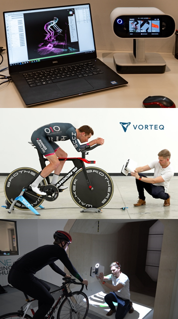
Vorteq is making use of a full-sized, sports-dedicated wind tunnel, a custom fabric wind tunnel, and the latest in 3D scanning technology to create custom skinsuits for cyclists. A skinsuit is essentially the most aerodynamic piece of clothing a rider can wear, reducing their level of drag down below that of being naked. A quality skinsuit should also be comfortable, lightweight, breathable, and made specifically for the athlete wearing it. Otherwise they’re bound to fit improperly and wrinkle up, and in the world of aerodynamics, every wrinkle adds to performance-killing drag. As well, many fabrics “open up” when overstretched, introducing greater drag across their surfaces, so fabrics and seams should be chosen carefully for specific areas of the body, with each skinsuit designed and manufactured to have the exact amount of fabric tension for that particular rider’s anatomy, to achieve optimum airflow and the least wind resistance. Considering how body shapes and sizes of cyclists can differ so dramatically, such a customized fit simply isn’t possible with an off-the-shelf, small-medium-large type of skinsuit.
Vorteq’s parent company, TotalSim, has deep experience from working closely with professional cyclists, Olympic cycling teams, Tour de France riders, and other top cyclists over the past 10 years. This has made it possible for Vorteq to create what they believe to be the fastest skinsuits available today. To engineer their skinsuits beyond what was ever possible in the past, Vorteq has invested in excess of $500,000 in R&D, while testing more than 45,000 different material, tension, and speed combinations in the specialized wind tunnels at Silverstone Sports Engineering Hub (SSEH). The end result is every athlete receives their own skinsuit, created with custom patterns and fabrics, each designed for maximum performance.
Despite Vorteq’s lengthy work exclusively with Olympic teams and other elite athletes, as of January 1st, 2020, their custom skinsuits are available to serious riders of all levels of experience. This means that any cyclist, not just the pros, now has the chance to get a custom Vorteq skinsuit, and when they’re sprinting towards the finish line, they’ll be wearing the same level of skinsuit technology as if they were one of Vorteq’s Olympic clients.
To create these custom skinsuits, the use of a 3D scanner is a crucial element for digitally capturing a rider’s exact anatomy, and in the hours that follow those few minutes of scanning, all the sizes, patterns, and types of fabric will be meticulously selected in the computational draping system and then assembled by Vorteq’s skinsuit team.
In the past, TotalSim was using an arm-based scanner for scanning race cars, bicycles, and other objects, but when it came to using the scanner for capturing people, they ran into significant difficulties and weren’t able to proceed any further with their old technology.
That’s when Vorteq turned to Artec Ambassador Central Scanning, specialists in all aspects of 3D scanning. During an onsite visit and consultation, the experts at Central Scanning recommended the Artec Leo, a revolutionary handheld 3D scanner with a built-in touchscreen and up to 80 fps capture rate, as well as being an entirely cable-free scanner that excels at capturing medium-sized objects such as people in mere minutes. TotalSim had used two Artec scanners in the past for their CFD and metrology work, Artec Eva and Artec Spider, so they were already familiar with Artec’s high level of scanning technology.
When Sam Quilter and his colleagues at Vorteq saw how fast and accurately Leo captured the exact anatomy of a cyclist, they knew they had found the right tool for the job. In the hours after taking delivery of their new Leo, they began creating their digital capture workflow, which Quilter described as follows:
“The rider comes into the wind tunnel with their bike, mounts it in place on the platform, hops on, and in just 5 to 6 minutes with Leo, I capture the rider in two positions in precise, high-resolution color 3D. And then I need just another minute to capture their shoe, on all sides,” Quilter said. “Basically this means that in ten minutes I can be totally done with that rider and they can go elsewhere. I’ve got everything I need to design an anatomically-accurate, fast-as-a-bullet Vorteq skinsuit. No chance of a rescan needed. Not once.”
Quilter continued, “We usually scan cyclists in their underwear, to get as much detail of the body as possible, so that when we design the skinsuits, they lay down perfectly over that cyclist’s anatomy in a way that just isn’t attainable if we’re designing from a scan that includes some overlying fabric blocking exact anatomical structures from view.”
“When we’re making our skinsuits, we’re working directly from the Leo scans, so it’s not measurements we’re taking, it’s the exact physical data that’s being used, and the difference is crucial. Because if you’re taking physical measurements and then entering them into a CAD system, or a computational draping system like ours, something is going to be lost in the transition. And that something can easily result in imprecise dimensions being used to create a skinsuit, which is entirely unacceptable to us. Even one tiny mismeasurement could result in a wrinkle here or there, or fabric being overstretched. So, for us, how Leo gives us the exact physical data of the athlete to work with makes all the difference.”
Quilter summarized the process, “From the time an athlete walks in the door and we start scanning with Leo, then using Artec Studio to post-process the scans, followed by 3D modeling work in Geomagic Wrap, and finally exporting the 3D model for use in making a skinsuit, we are looking at about 2 hours total, which absolutely wasn’t possible in the past, not even close. And as far as the total production time for a skinsuit that’s ready to race, currently we’re at 2 days, but that gap is narrowing, and we’re shooting for a 24-hour turnaround time, which we’re sure to hit before too long.”
Quilter explained his post-processing workflow in Artec Studio, “Leo makes it easy for me. Not many steps are needed in Artec Studio at all. I basically read the Leo data in, double-check everything visually, then use the Eraser tool for a few clicks to remove any occasional, unwanted bits. I normally keep the bike in the scan, since it’s a great reference point to get XYZ positioning as well as the angle, and then I go into Global Registration, where I just use the default settings because they work brilliantly as is. Normally I don’t need to do Outlier Removal, because the data is already clean enough for a person. Then I do a Smooth Fusion, and after a few other minor changes, I export it as an STL file for use in Geomagic Wrap.”
“In Geomagic Wrap, I use the Decimate tool to get the triangle count down further, and if I’m getting rid of any wrinkles, which shouldn’t be in the scan, but on a very rare occasion might be, I use the Relax command, and then I move on to the Smooth commands, which let me cut out any imperfections, because sometimes athletes twitch their fingers during the scanning, and we need to fix that. After we’ve done all we need to do, we export it as an OBJ file for use in our computational draping software,” Quilter said.
Vorteq’s newest offering is that of using their Leo to create scans for 3D printing anatomically-precise mannequins of athletes. These mannequins are then used to create new skinsuits for the athletes without them having to visit the Vorteq office. Let’s say, for example, that a cyclist is training on the other side of the world and needs a skinsuit specifically for an upcoming long-distance time trial that’s mostly on the flats but also includes a long downhill phase. By having a 3D mannequin of the athlete, Vorteq can create a custom skinsuit for them, test multiple fabrics and patterns in its wind tunnels, and craft the new skinsuit in the hours that follow, then express deliver it to them on the other side of the world, or anywhere. At present, the custom mannequin process takes just under 2 days, but that number is decreasing with each passing week. The target turnaround time is 24 hours from 3D scan to completion for creating a new 3D-printed mannequin.
Quilter spoke about the why behind 3D-printed mannequins, “A full-sized mannequin lets us do wind tunnel tests on fabrics in isolation on just an arm, for example, to see how various fabrics and patterns affect drag reduction. That’s where the marginal gains really add up. Because with a live rider in the wind tunnel, there’s going to be the wiggle factor to deal with, where the rider is moving around, even ever so slightly, and that’s going to affect results. With a live rider, you can never have the exact measurement possible with a perfectly still mannequin, where the only factor that’s changed is the fabric that’s been put on.”
“Mannequins don’t get tired, and they’re always perfectly still, which allows us to know exactly what kinds of changes our fabrics and designs are causing in terms of drag and performance.”
TotalSim also provides biomechanical consultation and training for cyclists and teams, advising athletes on which body positions, equipment adjustments, riding habits, and clothing will either enhance or diminish their power, drag, endurance, and more.
“Our mission is to help serious athletes, many of whom are already at the top of their game or near, find those many ‘tiny’ gains that when you add them all together, can really give an athlete the kind of edge that helps them surge over the top and on to victory,” Quilter said.
In addition to Vorteq’s skinsuits and TotalSim’s biomechanical consulting and training services, they also provide scanning services to a range of clients, including cycling teams. Their Leo has played a pivotal role in their ability to 3D scan anywhere their projects lead them, whether in-house, around the UK, or overseas.
As Quilter explained, “In contrast to our previous scanners, Leo gives us that flexibility to just pick up and go virtually anywhere in the world to do scanning, without requiring extra hardware, just the Leo itself. This kind of freedom is tremendous when you’re going offsite to random locations that aren’t exactly laboratories in regards to their conditions.”