Product: DMP Industry: Automotive and Transportation
Rodin Cars, a New Zealand-based car manufacturer, is using 3D Systems’ large-scale DMP Factory 500 metal 3D printer to produce the titanium components of its new bespoke track car, the Rodin FZERO. With performance and quality leading every engineering decision, the car is manufactured primarily from carbon fiber and titanium. 3D Systems’ metal additive manufacturing (AM) was selected as the production method for all complex titanium components to enable Rodin Cars to advance the design and performance of every part, regardless of size, including the eight-speed sequential gearbox – an industry first.
“Our goal was to make every component of this car the best that it can be. The Rodin FZERO can only be manufactured with additive manufacturing.”
Adam Waterhouse, Lead Engineer, Rodin Cars
Rodin Cars’ top priorities were to optimize for weight and function while using a non-corrosive material to maintain peak performance and appearance over time.
ACHIEVING LARGE-SCALE HIGH QUALITY TITANIUM PRINTED PARTS
Targeting a final weight of only 650 kilograms and producing 4,000 kilograms of downforce, the single seat Rodin FZERO (for “zero restrictions”) is engineered to lap a circuit faster than a current Grand Prix Formula One racer. With industry-changing engineering built into every component, Rodin Cars was intent on thorough optimization to deliver the ultimate component for every part.
When it came to using titanium additive manufacturing throughout the car, challenges arose as part sizes increased – particularly for large parts. Producing components like the gearbox to spec required a build volume beyond the capabilities of most metal printers. However, reverting to conventional methods of casting the gearbox in magnesium was not an option, as both the method and material would fall short of Rodin Cars’ objectives. To deliver the ultimate hypercar, Rodin Cars’ top priorities were to optimize for weight and function with AM, and use titanium for its value as a premium, non-corrosive material that will maintain peak performance and appearance over time.
Innovation to Create a Lightweight Gearbox
The first step in optimizing the gearbox was creating a custom design together with renowned gearbox manufacturer, Ricardo. Following extensive work with 3D Systems after first adopting AM, Rodin Cars shared its gained knowledge with Ricardo, educating them on the unique benefits and capabilities of designing and manufacturing with additive. Rodin Cars needed very specific gear ratios and case dimensions, and knew it could only produce its design using AM. Removing excess mass was also a top priority, yielding thin walls down to 2mm thick in some areas. The two companies collaborated to design parts around the optimized geometry Rodin Cars was after, integrating internal galleries and fluid channels to help reduce the footprint of the final gearbox, which measures 400mm x 650mm x 300mm.
To produce titanium AM parts with the required dimensions and accurate features, Rodin Cars selected 3D Systems’ direct metal printing (DMP) for its unique large-format capability and proven quality and repeatability.
The DMP Factory 500 delivers exceptionally strong and accurate parts with high chemical purity, and the repeatability needed for serial production.
Proven Titanium Workflow
Optimizing the power to weight ratio is critical for high performance vehicles. As such, the ability to print the complex metal components in titanium was key for Rodin Cars’ mission to deliver premium performance while taking out as much weight as possible throughout the car. The integrity of titanium as a non-corrosive material also means neither the looks nor performance will degrade over time, which was important to Rodin Cars founder, David Dicker.
According to Adam Waterhouse, lead engineer at Rodin Cars, effectively any component that is metal and isn’t a bolt is 3D printed. “Every bracket through to the gearbox has been printed,” said Waterhouse. “It’s an enormous range of parts. It’s very much a printed system.” The final titanium gearbox is printed in LaserForm Ti Gr23 (A), and weighs only 68 kilograms, including steel internals.
3D Systems’ complete metal solution includes 3DXpert software, an all-in-one software for preparing, optimizing, and managing the metal printing workflow. For each of 3D Systems’ LaserForm materials, this software includes extensively developed print parameters, packaging the expertise of 3D Systems’ engineers within the workflow. The unique system architecture of 3D Systems’ DMP machines is also designed to enable full material usage without degradation.
The DMP Factory 500 is the only available scalable metal additive manufacturing solution capable of producing high quality seamless large parts of up to 500 mm x 500 mm x 500 mm.
Large Scale Metal 3D Printing
Rodin Cars initially planned to split the gearbox into multiple smaller components and print them in-house using their legacy ProX DMP 320 machines. To spare them this extra effort, the engineering team was excited to learn about 3D Systems’ DMP Factory 500, the only available scalable metal additive manufacturing solution capable of producing high quality seamless large parts of up to 500 mm x 500 mm x 500 mm. Using this new platform, the gearbox can be produced as an assembly of only four sections that can be produced in a single build.
The DMP Factory 500 features best-in-class oxygen levels (<25 ppm) and an inert printing atmosphere to ensure exceptionally strong and accurate parts with high chemical purity, and the repeatability needed for serial production. According to Waterhouse, this quality was put to the test with the thinly-walled cases of the gearbox, measuring just two millimeters thick.
“These prints were proven to be extremely accurate,” said Waterhouse. “On our largest section, which is enormous, there was only 0.2-degrees twist in the part, which is really impressive. Not to mention, we have all the benefits of additive with the internal channels and incredibly thin walls that would be impossible to achieve any other way.”
Metal Expertise from Application Innovation Group
To expedite access to large-scale metal printing in advance of the installation of its own DMP Factory 500, Rodin Cars worked with 3D Systems’ Application Innovation Group (AIG) to get the first titanium gearbox printed. 3D Systems’ AIG is a global resource equipped with the experience and technology to support AM applications across industries, and can advise and assist on projects at any stage, from application development and frontend engineering, to equipment validation, process validation, and part qualification.
3D Systems has provided Rodin Cars with ongoing knowledge and technology transfer since it first adopted additive manufacturing, helping the car company to increase its understanding of necessary principles for success with AM design and production. However, the shift to a large-scale printing format required a new set of best practices. 3D Systems’ AIG provided engineering and application development services to help Rodin Cars prove its concept, including final programming of the four gearbox components and printing of the first gearbox. 3D Systems also provided the programmed build files and technology transfer to accelerate Rodin Cars’ path to successful large-scale metal printing following the installation of the DMP Factory 500 at Rodin Cars’ facility.
Product: Solid Edge Industry: Automotive and Transportation
Developing fresh, disruptive solutions for automotive and motorsport
In 2017, Ashley Warne, chief executive officer (CEO) and chief engineer of Dynisma Ltd., founded the United Kingdom-based driving simulator company after leading the in-house simulator development efforts for F1 at both McLaren and Ferrari. “Working in high pressure, excellence-led teams with significant resources instilled the belief that these efforts could be applied differently,” says Warne. “Access to the most advanced, high-fidelity, responsive motion generators that engineers could want should be made available to all.” At Dynisma, Warne is responsible for technical leadership and developing simulation concepts.
“Dynisma produces the most dynamic, responsive and scalable driving simulators in the world. Our team of world class engineers have taken on a fresh perspective and invented new solutions for automotive and motorsport,” states Warne.
Dynisma Motion Generators (DMGs) are fully immersive, offering the perfect solution for a range of audiences, such as motorsports teams that want to optimize driving and car performance or automotive manufacturers and suppliers that need advanced vehicle development and testing. The DMG delivers maximum bandwidth with minimum latency, which means that the simulator reacts very quickly to commands – in this case, response happens in 3 to 5 milliseconds. This is possible because the team co-designs software and mechanical engineering aims to remove every possible obstacle between the driver and the data.
DMGs are produced for all use cases in driving simulation for automotive and motorsport. The simulator also includes visuals, mock-up chassis, vehicle models and environment simulation. “DMGs are at least 50 percent better than any other comparable solution in the world and equally affordable,” states Warne.
Designing the DMG
“The development of DMGs always starts with embodying our unique selling points,” explains Matt Bell, head of mechanical engineering at Dynisma. “The process begins with a conceptual state, which gives the team a broad layout of the system before it is handed over to mechanical engineering. Then we identify and set all the key dimensions and components that will comprise the DMG. Once we feel like we have that arrangement correct, we tend to spread the work out to the rest of the team who will detail, draw and transform it into something that is producible. We also work with various suppliers who manufacture the structural parts – whether it is through formed metal work, computer numerical control (CNC) machined and 3D-printed components, or a composite structure.” Once the team figures this out, they have subassemblies or components come in for assembly and test.
“All our systems have very low latency,” summarizes Warne. “When we want a driver to feel that they are being moved – for example, from oversteer – this will happen in 3 to 5 milliseconds.” DMGs can be used to simulate any event like road texture, rumble strips, oversteer feedback and noise, vibration and harshness (NVH). Delays of milliseconds can have a huge impact in terms of the feedback given to the driver and their response.
Overcoming challenges as a startup
Like any startup, Warne and his team found the process of getting a business off the ground to be a challenging endeavor. “One critical success criterion is probably how fast you can bring your solution to the market,” Warne reflects. “That’s why we were looking right at the beginning for affordable yet advanced software to fulfil our needs in the mechanical design process of modeling and drafting, as well as a system level structural simulation solution.
After studying what was available on the market, Dynisma turned to Siemens Digital Industries Software and its Solid Edge for Startups program, which provides eligible startups with free access to a complete portfolio of product development software tools.
Along with one year of free Solid Edge® software, the program provides access to training resources, best practices and guidance from experts.
“When you are a fresh business with fresh investor funding, one of your primary focuses is making the capital you raise go as far as possible. So, the Solid Edge for Startups program was quite attractive at that time,” explains Warne. “It gave us this runway with a fixed cost for a certain amount of time, which provided flexibility in terms of licensing and enabled us to scale up as we took on new designers.”
As Dynisma applied for the Solid Edge for Startups program, they found the process to be painless. “We were able to quickly get the software licenses in place and integrate it with our cloud-based file sharing. From here, it was easy to get people up and working,” explains Bell. “When we were testing competitor options, some were more difficult to get and didn’t work properly a month in. With Siemens’ solution, the ease of setup and integration was a big influence on our decision.” By using Solid Edge, Dynisma’s onboarding licensing support process is now significantly faster compared to competitors. They can be up and running in days versus months.
Excellent support and advanced features
“The Solid Edge for Startups program was appealing because it offers the full digitalization portfolio covering mechanical and electrical needs with high quality technical support,” states Warne.
Dynisma has found Solid Edge to be the most useful for producing 3D models, rendering, drafting, simulation and for its built-in data management functionality, which enables them to manage new and existing files. The integration between applications allows Dynisma to significantly increase efficiency in their workflow. “The built-in data management system is a useful element that is not available in some other software packages,” states Bell. “We found the sheet metal modelling capabilities of Solid Edge to be excellent. It’s both powerful and user friendly enabling our new starts to quickly get productive with minimal rework.” Also, the assembly instructions are produced in Solid Edge. The team builds up the machine and moves through their verification and validation (V&V) activities and factory acceptance testing.
Siemens solution partners IC Blue and OnePLM also offered valuable support, making sure Dynisma got set up with licenses and received technology support during the implementation. Since then they have provided technical support and training for new team members at Dynisma. The quality of available technical support was one of the key reasons why the team chose the Siemens’ solution. “It was easy to get fast and reliable support from skilled people who could answer any question,” explains Bell.
Additionally, although Dynisma has scaled up and become more autonomous, they still benefit from the technical support, which enables them to discover and explore additional capabilities included in the software so they can become more proficient. “If we are experiencing an issue, the technical support team will set up an educational session and enable us to better understand how to overcome a problem,” states Bell.
Getting up to speed in days
The ease of onboarding and using Solid Edge has enabled Dynisma to rapidly bring team members up to speed and ultimately help them grow. “One way Solid Edge enables us to meet our design goals is that it is easy to pick up,” Bell explains. “We can find people who have used other Siemens packages, like NX, and they can quickly find their way around Solid Edge. Additionally, we have had several people come in who have used different packages who can pick up the software in a few days and produce useful work. This helps because it enables us to be responsive.
“It is now very easy to produce offers quickly, which also helped speed up our design and delivery processes – in the end the whole customer experience benefited from that shift.”
Going from startup to scaleup with Siemens Mechanical Design software
After the end of their startup phase, Dynisma expanded their product development capabilities to a new level by implementing Siemens Mechanical Design, which includes access to capabilities from both Solid Edge software and NX™. “Choosing this solution can enable us to grow while still being flexible enough to set the focus we want,” reports Bell. “After having an excellent experience with Solid Edge, the step to Siemens Mechanical Design was logical. It makes it easier to transfer in and out with NX files, improving interoperability with other software.”
The Siemens Mechanical Design software, including Solid Edge software and NX software, are part of the Siemens Xcelerator portfolio, the comprehensive and integrated portfolio of software, hardware and services.
The package itself provides a single source for all mechanical computer-aided design (MCAD) purchasing, licensing, training and service needs. “For us the main advantage of Siemens Mechanical Design besides agile licensing was to provide each designer or engineer with the features and functions needed for the specific development process they were assigned to. This was to maximize design capabilities while lowering total cost of ownership,” says Bell.
It is crucial for Dynisma to continuously produce conceptual models and develop detailed designs with them. Since it is a highly integrated package, they can do so. Along with the ability to pick it up quickly, there is a flexible licensing model where they can pay by the month in the case of a short-term contractor.
“As we grow, we plan on continuing to explore Siemens Mechanical Design, moving toward using more capabilities with the hybrid licenses,” states Bell. Looking further down the road, they will continue to broaden access to their groundbreaking technology, offering industry leading responsiveness in new sectors and markets.
Product: Figure 4 Industry: Automotive and Transportation
Hankook Tire & Technology is more than a tire manufacturer. With a focus on automation and technology that will enable “The Future Driving Innovator,” the Seoul-based company has put electrical vehicles at the center of what they do. Recently, Hankook needed a way to quickly and cost-effectively drive innovation by iterating multiple plastic and elastomeric designs with complex geometries for its i-Flex nonpneumatic tire (NPT), which would eventually become a key component in Hankook’s award-winning HPS-Cell autonomous mobility platform. By leveraging 3D Systems’ plastic and elastomer additive manufacturing technologies, Hankook’s Design Studio was able to quickly iterate designs and share production-grade parts among their designing, and testing teams while reducing costs.
“The main purpose of using 3D printing is to communicate better with R&D before they build the actual mold to produce the tire. The traditional molds are machined and cost a lot of money and time to develop, but that’s also been the conventional way to figure out a new design, shape, and even volume. Now, using additive manufacturing technologies from 3D Systems, we can work faster with R&D to figure out the shape or structure using small portions of the structure and then test our prototypes for safety, noise, and other parameters.”
– Rosa Youn, Design Innovation Studio Manager, Hankook Tire & Technology
The Challenge
Expedite multimaterial, complex tire and wheel designs and testing while cutting costs
Hankook Tire & Technology understands that autonomous mobility solutions of the future require a new generation of tires that combine minimal maintenance with maximum safety and comfort. With their low maintenance and increased safety, NPTs are predestined for this field of application but developing an NPT that checks all these boxes presented a complex and costly design challenge. Hankook designers believed that a biomimetic design that mimicked biological tissues would provide internal support for the NPT, but with a nearly infinite number of possible cellular structure designs, Hankook’s Design Studio needed a way to quickly evaluate partial parts as well as scale complete models.
Traditional prototyping methods for new tires often started with a 2D sketch, transitioning to a 3D CAD design that would be translated into an aluminum mold through skilled human machinists. The entire process was too costly and too slow, with each iteration taking potentially weeks or months.
Furthermore, the NPT’s biomimetic supporting “spokes” matrix challenged even the most capable machining stations due to its complex hollow, interconnected structures. After exploring multiple additive systems for rapid prototyping and low-volume production, Hankook chose 3D Systems’ Figure 4 technology platform for the plastic support structures and rubber tread. Hankook also turned to 3D Systems’ partner CP Tech for selective laser sintering (SLS) for conepting the metal tire structures and hinges, which turbocharged the development of their i-Flex NPT prototypes. The result, as Hankook designers like to say, is the future of mobility.
The Solution
1 – Spoke Structures for Nonpneumatic Tire i-Flex
Various iterations and concepts of spokes printed with 3D Systems additive manufacturing technologies (r) that led to the final design of the Hankook HPS Cell (L)
Hankook’s NPT tire includes a complex biomimetic plastic matrix for internal support, an elastomeric external tire tread, and metal parts that perform some of the support functions of a tire rim plus additional functions necessary for autonomous vehicles. Machining these hollow structures in plastic would be nearly impossible.
“For us, because of [3D Systems’] additive manufacturing technologies, we can design or make anything we want to or anything we can imagine. This technology can eliminate the limits of manufacturing, which is really great for us. With traditional product design for example, building and machining, there are a lot of limits. Machine tools have limits. Additive manufacturing does not have these limits,” said Hee Sung Jang, Design Innovation Studio Designer, Hankook Tire & Technology.
Using the Figure 4 platform, Hankook designers are able to quickly iterate different support matrices using Figure 4 PRO-BLK 10 plastic with its thermoplastic-like mechanical properties. The Hankook Design Studio team could quickly turn 3D designs of different biomimetic matrixes into partial or scaled prototypes that maintain the same cellular spacing ¬— which is critically important to downstream testing — all while constraining development costs. With partial parts that include full-scale cellular structures, Design Studio designers could quickly gauge relative strengths among candidate designs using physical testing before proceeding into full tire assembly.
2 – Noise Control Testing on Tire Segments
Tires, including NPT tires, need to be safe and durable, but they also need to be aesthetically and acoustically pleasing. In short, people won’t buy ugly tires, and they won’t keep buying loud tires. After developing the NPT support matrix, Hankook Design Studio designers were able to develop partial and scaled tread designs using Figure 4 RUBBER-65A BLK elastomeric materials.
“By using those materials and partial parts, we can evaluate the part for noise and safety,” said Mrs. Youn. “The test system flows air or water into the channel or groove, [and] we measure the noise to understand if the structure is correct or not.” She added that in the future, building these treads in translucent Figure 4 material will make the process even easier, allowing engineers to see how fluid travels down the tread grooves, a key part of tire safety in adverse weather.
Additionally, printing tire treads makes it easy for manufacturing engineers to evaluate new NPTs for stability and potential cracking and reduced reliability.
Hankook’s NPT design includes plastic components for internal support, rubber materials for tire tread, and metal components for tire rim and support. All three elements are shown here.
3 – Moving Parts on New Concept–Type Tires
Additive manufacturing’s ability to develop complex shapes also allowed Hankook designers to develop internal grooves and structures that help connect the tires’ three primary elements: tread, NPT support matrixes, and moving thermoplastic rim components. The thermoplastic components were manufactured by CP Tech, using 3D Systems’ SLS technology. This was new to Hankook, as traditional tires don’t consist of any moving parts.
“One of the main reasons we chose 3D Systems over the competition is that their material selection is so broad,” said Rosa Youn, Design Innovation Studio Manager, Hankook Tires. “It covers all the material requirements we have. In addition the Figure 4 is fast. Time saving, reliability, service, best troubleshooting, and also availability of the system and reasonable price were our key decision factors. We believe in the value of 3D Systems’ Figure 4. For me it is one of the best additive manufacturing systems in the world.”
4 – Standard Visual Prototypes of Tire Profiles
Hankook Design Studio has already expanded the use of the Figure 4 platform, using it to develop traditional tire treads and profiles for testing. This is allowing for faster iterations of all new product designs, not just the revolutionary but the evolutionary as well.
In addition to helping Hankook’s Design Center quickly develop and test NPT tire designs, the company can also use it to quickly evaluate new tread designs for road noise and other key factors, reducing time to market and costs for all new tire designs at Hankook.
In addition to helping Hankook’s Design Center quickly develop and test NPT tire designs, the company can also use it to quickly evaluate new tread designs for road noise and other key factors, reducing time to market and costs for all new tire designs at Hankook.
Product: Solid Edge Industry: Automotive and Transportation
Supporting the electric mobility ecosystem
eNovates is a rapidly growing technology company driven by mobility and sustainability. The company was founded in 2010 as a think-tank in a business club focused on developing and producing charging systems and energy management software to support the electric mobility ecosystem.
eNovates is expanding in the European Union and has an important market share in delivering public charging infrastructure, with about 80,000 charging stations installed in early 2021. The company is expanding its reach into smart energy management and recently added a vehicle-to-grid (V2G) charger to its portfolio. Its customers are charge point operators (CPOs) – companies who sell charge points, connect them to networks and provide maintenance. eNovates serves its CPO partners as an original equipment manufacturer (OEM).
“Some of our customers approach us with no more than an idea for the final product. In this case we can base ourselves on a set of generic platform components and products to realize the best-fit custom product for the customer,” explains Stijn Vispoel, research and development (R&D) manager at eNovates. “Others come to us with an enclosure and ask us to develop a charger for it. We do full projects for them, and all solutions include mechanical, electrical, electronic and software components.”
Product development for rapidly changing requirements
Technologies, regulations, standards and customer requirements are evolving quickly in the electric mobility ecosystem. “The biggest challenge is the constantly and rapidly changing guidelines in the market,” Vispoel says. “We have to be on top of all the new developments and we really need a new product every year. It’s important to have enough R&D capacity to keep up with the changing requirements for charge points. Another factor is the different regulations in different countries in Europe. For example, customers in the Netherlands have different requirements than customers in France.”
Vispoel leads a team of project managers and support personnel with varying back-grounds in mechanical, electrical and electronic engineering. “We begin each project with a prototyping phase where we develop the printed circuit boards we need, the electrical wiring and mechanical components,” Vispoel explains. “Once we do all the checks on the digital design files, we make some prototypes and do test runs to confirm that they comply with the customer requirements and regulations. Then we enter what we call the alpha phase, redesigning any components that need modifications. We make another batch of the product, around 30 to 50 chargers, and do another validation run, performing temperature and high-voltage tests. We also have customers who use them to charge cars and run additional tests.”
In the next stage of development, the beta phase, eNovates makes necessary design modifications and orders a new batch of the product. “We go directly to certification labs with the beta chargers, and place about 100 chargers in the field with our customers, so we are certain that the product is mature enough and it’s fully certified to go into the market,” says Vispoel. “At that stage we typically don’t develop the hardware further – the focus is on finishing the software. Finally we go into production for our customers.”
Disparate systems and information silos
Over its history, eNovates had acquired engineering software systems for mechanical computer-aided design (MCAD), two different printed circuit board (PCB) design solutions, and a system for electrical wiring and harness design. The systems had been selected based on engineers’ prior experience and partners’ and customers’ use of the solutions.
This software landscape had some limitations: The MCAD system lacked electrical design functionality, the wire harness design system had no 3D capabilities and neither system easily exchanged data with the PCB design tools. The four separate and disconnected software solutions created information silos that hampered interdisciplinary collaboration. Each software package used different data formats that impeded transfer of information between disciplines. Because the software was purchased from different vendors, the new versions of each software solution were not synchronized with the others and eNovates had four different sources of support.
Using this approach, the mechanical design team sent their design models to the electrical team, which amended the designs and returned them to the mechanical team. These iterative design exchanges continued over weeks and months, resulting in huge design and prototyping costs and product launch delays. The information silos and barriers between systems made it difficult for eNovates to fit electrical designs into mechanical spaces. They also created problems in communicating design information to contract manufacturers. eNovates was sending confusing and disconnected details of the design for manufacturing, which resulted in issues with requirements and regulations.
Integrating engineering disciplines and solutions
To eliminate the workflow inefficiencies, eNovates searched for an integrated software toolset that better suited the fast pace of development. From contacts at Ghent University, the eNovates team was introduced to Solid Edge® software, which is a part of the Xcelerator™ portfolio of solutions and services from Siemens Digital Industries Software and a leading mainstream product development platform.
eNovates contacted ADOPT id PLM, a Siemens solution partner in Belgium. After an initial meeting, ADOPT id prepared a presentation for eNovates that included Solid Edge and its integrated electrical design and technical publishing tools. The demonstration illustrated how all of the Solid Edge mechanical design, electrical wire routing and harness design, and technical publishing applications were fully integrated and used the same data format and user interface conventions. ADOPT id also proposed Siemens EDA (formerly Mentor) PADS Professional software, also integrated with Solid Edge, for PCB design and verification (PADS is supported by Siemens EDA solution partner Innofour). The presentation also emphasized the bidirectional data flows and associativity across the mechanical, electrical and electronics domains – design modifications in each discipline are automatically reflected in the others.
eNovates quickly made the decision to choose the proposed Siemens solution for several reasons. “We wanted all of our software tools to work together so we could have a streamlined design flow for our fastpaced development,” Vispoel explains. “For complex products with high quality standards and efficient production, we needed to transfer information very efficiently. The Siemens software offered us a better match to help us make fewer errors in our design iterations. We didn’t find this level of integration anywhere else in the engineering software market. And we regard Siemens as a very big technology provider, a market leader in software and a brand that delivers quality.”
Documenting designs for manufacturing
“We fully outsource our production,” Vispoel says. “We deliver the contract manufacturer a full package of information on how the product has to be made, how to test it, how to package it. And then they translate what we do in engineering into making the product. They source every component, make every PCB and test everything based on the instructions we provide.”
With its previous software solutions, eNovates could deliver a 3D file depicting the mechanical design, electrical drawings, and three separate bills of materials (BOMs) for drawing mechanical, electrical and PCB content. However, the information was not well integrated, and its delivery was not efficient.
Solid Edge Technical Publishing software offered eNovates a superior solution for preparing information for manufacturing. Now, the manufacturing package includes a unified BOM for the entire product, which is especially useful for pricing. For PCB manufacturing, a standard format file produced using PADS Professional software includes information about each physical board layer and coordinates for PCB objects like copper traces, vias, pads and solder masks. For electrical manufacturing, Solid Edge Technical Publishing software extracts the list of cables and their locations, connections, cut lengths, and torques required on their connecting screws, all produced using the Solid Edge electrical design software. With the Solid Edge 3D model, the publishing software fully and visually describes each step in the product assembly and testing processes.
Streamlined workflows boost efficiency
With the new integrated toolset, eNovates benefits from improved efficiency throughout the development and manufacturing cycle. “This was a big win for us,” Vispoel says.
Solid Edge 3D design software includes synchronous technology, which enables eNovates to edit CAD data from any source and leverages built-in product data management and cloud collaboration tools. Solid Edge electrical design satisfies eNovates’ need for 3D wiring and harness design and validation in mechanical assemblies.
Solid Edge technical publishing has helped eNovates improve the clarity, accuracy and completeness of manufacturing information in comprehensive case files. The integration of PADS Professional with Solid Edge has helped improved communication between PCB designers and mechanical engineers.
Product: HandySCAN Industry: Automotive and Transportation
How Hyundai Design North America uses HandySCAN 3D for improving real-time design workflows
Opened in January 2003 and located in Irvine, California, Hyundai Design North America’s design and technical center is a 90,000 square foot, $30 million state-of-the-art facility where automobile designers, engineers, model makers and other experts create new vehicles. The team offers alternative designs for its parent company based in South Korea.
As is the case with the vast majority of automotive manufacturers, clay sculpting plays a vital role in the design process in Hyundai Design North America’s studios in order to fine-tune concepts based on scale models and full-size clay vehicles. Clay modelling to design vehicles is still a very common practice with today’s automotive manufacturers to assess design quality and get feedback from reflection-based surfacing.
However, with today’s amplified competition for consumers as well as manufacturers’ accelerated time-to-market development and production schedules, design teams are under increasing pressure to create concepts faster than ever before. Digital modeling using 3D measurement technologies, such as portable 3D scanners, has become a vital solution in order to speed up design workflows.
Legacy 3D scanners no longer fitted the performance bill
For a long time, Hyundai Design North America, which is an early adopter of new technologies, used 3D scanners as a complement to its clay modeling and design processes. Unfortunately, at one point, the team realized it was time for a major equipment upgrade.
“The scanners that we were previously using were too bulky and difficult to manage. The scanning process and post-processing times were long and required most modelers to step away from working on the clay,” explained Rob Homer, Operations Modeling Manager at Hyundai Design North America. “This led to crucial time loss, especially when deliverables had hard target dates.”
Rob and his team began checking out available 3D scanners that fit their requirements. “We wanted a 3D scanner that was compact, easily portable, fast and accurate. It also had to be compatible with our CAD software.”
HandySCAN 3D: A clear front-runner in 3D scanning for designing vehicles in the automotive industry
“After looking into the various 3D measurement technologies out there, Creaform came on top for me with its HandySCAN 3D. It is a very good and reliable product at a very good price point,” Rob added. He was equally impressed with its ease of use and speed.
Hyundai Design North America was able to seamlessly implement HandySCAN 3D into its existing design workflows for real-time development. Training users on the software was completed in a day. “The experience from purchasing the scanner to training was incredibly pleasant and professional.”
Once the 2D sketch is settled, digital modelers get to work on the 3D clay models and mill it out for verifications and fine-tuning. Changes are performed by hand on the clay model, which is then 3D scanned to acquire the digital representation of the modifications.
“The scanning process is quick and easy. We are able to scan selected areas of the model without disturbing anyone working around it,” he said. “We can relay information to the digital team within minutes after finishing the scan.” This quick turnaround time of the scan data to the digital modeler means that affected areas can be fixed quickly to mill the model again before final reviews.
Richard Gillespie, Senior Digital Modeling Manager, says that the 3D measurements enable the modelers and design team to know exactly where the clay models are landed in comparison with design criteria and styling boundaries. They can quickly identify and correct discrepancies. Designers can come to decisions faster thanks to the efficiency and accuracy HandySCAN 3D offers.
One of Rob’s favourite aspects is HandySCAN 3D’s simplicity. “My modeling team can use it independently without having to wait for another expert to do the scans for them. That makes our services a true one stop shop.”
Hyundai Design North America will continue to improve their clay modeling workflows using 3D scanning in order to allow more time for the design process and refinement. We look forward to seeing the new designs hit the market!
Product: NX, Simcenter Industry: Automotive and Transportation
The rise of Scuderia AlphaTauri
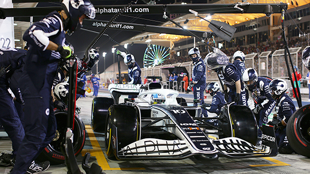
On February 23, 2022, the world got a taste of the new Formula One (F1) cars as they completed their pre-season test days in Barcelona. This was followed by testing days in Bahrain in early March 2022, where the drivers focused on getting comfortable driving the new cars before the race season began on March 21, 2022.
During the test days and the first few races, two young Scuderia AlphaTauri drivers, Pierre Gasly and Yuki Tsunoda, worked with the Scuderia AlphaTauri engineers to discover how the new car performed and fix the mistakes that occurred with the new design.
“There are new things to discover with this car every time we go out on the track so we have to make the most of each session and learn as much as we can before the first race here,” says Pierre Gasly, trackside during the test days in Bahrain in March 2022. “The feeling was unique. I was excited to discover these new cars and see how they felt on the track.”
That feel-on-the-track performance enhancer
In F1 racing, the driver and the car become one. This feel on the track comes from the part of the car that normally doesn’t get to be in the spotlight, the driver’s seat.
“The chassis is one of the most sophisticated parts of the car for safety and performance reasons. You need to start working on that part immediately even if you don’t have all of the information,” says Raffaele Boschetti, head of information technology (IT) and innovation for Scuderia AlphaTauri. “Before partnering with Siemens, we spent three months producing a good chassis. With Siemens software, we did this in one month. This saved us a lot of time and gave us many advantages.”
Aside from the chassis, the seat is important for driver safety and overall driver performance. Overall seat design is strictly regulated by F1 safety and crash test rules. If something goes wrong, drivers need to be able to exit the car quickly and safely. The safety marshal and medical teams need to be able to extract injured drivers from a crash effectively. Boschetti is quick to point out that there is much more to the seat in an F1 car than just safety.
“The seat is a part of the car that delivers performance. The driver feels all of the vibrations, accelerations and handling through the seat. On the track, we can modify the car settings to improve the car based on the driver’s needs,” says Boschetti. “In Formula One, you have a couple of tests in February or March. In this situation, the software and platforms Siemens provided us were vital to building the seat.”
One size does not fit all
Not every F1 seat is the same. Composite design engineers will tell you that half of the challenge isn’t the seat but how to fit the driver in the car.
“It is like a tailored suit. You have to look at things in terms of helmet position, back position and you have to be as low as possible,” says Francesco Dario Picierro, senior composite design engineer for Scuderia AlphaTauri.
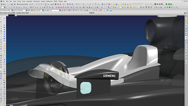
To ensure these critical performance aspects were correct, Picierro and his colleagues developed a unique seat-designing process. To start, they designed a slightly larger seat than necessary and then heated a batch of special resin and took a physical mold of the driver’s body in the ideal position. From the resin mold, they used NX™ software to create a complete scan to design the seat. NX, the Fibersim™ portfolio and Simcenter™ software are part of the Xcelerator portfolio, the comprehensive and integrated portfolio of software and services from Siemens Digital Industries Software.
“The process might seem simple, but thanks to Siemens’ products it becomes smarter,” adds Picierro.
Using digitalization for F1 success
With the complete design and chassis change in the 2022 model, the team had to simulate every detail in computer-aided design (CAD) from overall visibility to how the driver would fit into the chassis design.
Getting the driver to squeeze in, reach the pedals and obviously see – while considering the helmet, safety regulations and the new chassis and car design – is an engineering feat in itself. The team knows that digitalization is the only way to succeed in F1 these days. Using Siemens’ digitalization tools removed most of the grunt work from the design, engineering and production cycles.
“Using NX helped us with our digitalization efforts. For example, we can replicate the exact handwork on the steering wheel or the visibility using the driver’s camera. We can also scale the digital mannequin according to the measurements of the driver,” says Picierro.
Racing against the clock
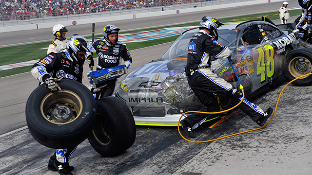
While the composite design engineers are custom fitting the driver to the seat (a process that can happen several times per season based on the needs of individual drivers) other members of the Scuderia AlphaTauri engineering team are optimizing the new car design for driver performance in time for race day.
Aside from the tight deadline, the other challenge for every F1 engineer is weight. F1 engineering teams struggled to make the minimum driver plus car weight of 795 kilograms (kg), especially with the new safety regulations and ground effect pull. At the last minute, the teams reached a compromise to increase the weight to 798 kg.
“Of course it’s always difficult. It’s a completely new regulation. These cars are complicated and it is difficult to design everything to meet the weight limit requirements. As we can see, nearly all of the teams are overweight. We also have to consider costs. It is expensive to reduce weight. Considering the cost cap, our teams were able to come to a compromise,” says Franz Tost, team leader for Scuderia AlphaTauri.
Zooming around over 300km/h during a normal F1 race, drivers experience up to four or five lateral G’s routinely under braking and cornering and during acceleration on the long stretches.
One platform and a secret to success
As Tost explained, balancing design parameters is always a challenge for engineering teams. Using the same digital platform and software suite to examine the real behavior of the car helps the team make the right decisions for the races.
“Our job is to evaluate the strength and stiffness of the part. The driver’s seat needs to be strong enough to support the acceleration loads and stiff enough to make a proper interaction between the driver, the chassis and the rest of the car,” says Giuseppe Stiscia, a chassis group leader and structural engineer for Scuderia AlphaTauri. “We use Siemens Simcenter to generate the finite element model and generate the load model conditions.” Simcenter clearly shows the standard stiffness values of the structure via a color strip. Each color represents a state of stress or displacement of the part.
“Structural engineers use this information to understand the real behavior of the structure. Our goal is to make the part as strong and stiff as possible, but we need to optimize the weight first. He adds, “Simcenter helps us calculate the part faster and use the same platform for everyone involved in the project.”
Development time is gold
Andrea Rizzo, a research and development (R&D) digital layup group engineer, uses this same platform with his colleagues. They use Fibersim tools to finish the actual part.
“We use Fibersim to achieve a perfect connection between the FEA results and the real lamination,” says Rizzo. “With this material, you need to cut a shape in the ply to be laminated on the mold. Any extra or unnecessary material applied to the mold is an additional cost. We try to laminate with as little material as possible to save time and money.”
The Scuderia AlphaTauri engineering team also uses Fibersim to maintain the consistency of the customized parts. Unlike commercial vehicles, F1 cars contain many handmade carbon fiber parts created by carefully layering composite plies inside the laminate. Each part has unique structural characteristics. Although the team wouldn’t say for competitive reasons, one can guess that spare parts and replacement parts are created on an as needed basis.
Data is king: any piece of information the team can analyze will help them understand the performance behavior of the new car.
“Each carbon part is a laminate, so we need to make sure the first one is the same as the last one. This is why we use Fibersim. We save time during the production process with this comprehensive simulation. We can prepare plies to be the same for all laminations.
“With Fibersim, we know what is happening in the component. We know the quality standard of the plies. We follow every single ply during the process. We can prevent problems before they happen because we ‘live’ in the same platform from NX to Simcenter to Fibersim. And more importantly, we save time,” says Rizzo.
“The problem with F1 especially – but even for standard cars – is that you need to produce the same part with the same quality at the same time. If you use the same suite that calculates everything for you from the CAD part to the production line, then you end up with a quality part that will deliver performance on the track. That’s the goal,” says Boschetti.
Thanks to Siemens Xcelerator tools like NX, Simcenter and Fibersim, the team can customize each seat to the driver using layers of composite plies to create a hyper-light-weight laminate that performs well to achieve safety and design specifications for the new Scuderia AlphaTauri cars. This provides Gasly and Tsunoda with the ideal connection to the car they need to perform well. Thanks to some superb engineering from the team in Faenza, Italy, and help from the Siemens Xcelerator portfolio, the Scuderia AlphaTauri team is more than ready for the upcoming F1 season.
Product: NX CAM Industry: Automotive and Transportation
It’s all about speed
Speed is the essence of auto racing. The first car to the finish line wins, so it is the responsibility of every crew member – including those who work at team headquarters designing and building parts and systems – to do whatever they can to help make the cars go faster. Engineers, designers and machinists work year-round, improving and refining their team cars’ engine and drive train performance, fabricating parts and systems, and responding to rule changes from racing governing bodies, such as IndyCar and NASCAR.
Siemens PLM Software helps racing teams achieve their goal of making cars go faster by providing a variety of tools to help users get up-to-speed on using its software systems, including Learning Advantage, an Internet-based learning management system. Learning Advantage is a convenient, easy-to-use e-Learning portal that provides cost-effective and time-efficient methods for users to gain skills and knowledge of Siemens PLM Software solutions. This system provides access to an unparalleled library of self-paced courses and assessments, as well as management tools for companies to measure learning progress and to administer learning programs.
When you can’t get to a class right away
“Hectic racing schedules can make it tough to attend traditional classroom training,” says Scott Graves, Engineering Operations Manager at Andretti Autosport™, an IZOD IndyCar Series™ team. “Learning Advantage has made training possible even in the middle of the racing season.”
“Sometimes new employees will not have an opportunity to attend a class right away based on course or workload schedules, and Learning Advantage will get them up-to-speed until a live course is available,” says Jon Rittle, engineering designer, Vehicle Dynamics Group at Joe Gibbs Racing, a NASCAR team. “Learning Advantage is also great for advanced CAD (computer-aided design) users who are familiar with other systems, but new to NX™. They can pick and choose the courses that will benefit them the most. And it’s always there to go back to as a refresher, or reference tool.”
Hendrick Motorsports, another NASCAR team, has similar experience with Learning Advantage. “We use Learning Advantage almost daily,” says Jim McKenzie, engineering applications manager at Hendrick Motorsports. “All of our licenses are in use constantly.”
Racing teams often field multiple cars in each race, and the lifespan of an engine is usually one race or less. So, shop crews are constantly fabricating parts and building new engines for their own teams, and in the case of Hendrick Motorsports, building engines for other teams. Over the course of a season, racing teams build hundreds of engines, not to mention numerous other car parts and systems.
Program expansion and new hires create an ongoing need for training. “As employees are promoted throughout the company, and we hire new employees, the need arises for more training,” says Rittle. “Like a lot of companies, we haven’t the resources that we would like to have, so we try to schedule our in-house ‘core functionality’ training classes quarterly, when possible. That said, there can be a gap in time from when a training need arises and when the next scheduled class is available. At times like this, we leverage the capabilities of Learning Advantage to help get users up-to-speed and proficient in their daily duties, and to prepare them for the in-house training classes when they become available.”
A continuous need for training
Even trained users need additional training. “Several of our engineers are occasional users and online training enables them to quickly brush up on features that they haven’t used recently,” says Graves. “They can also broaden their skills at their own pace.”
Training can help users renew their skills, as well. Graves notes, “Recently we hired a new designer who had been away from NX for several versions. He easily picked up with the current version using online training as a refresher course.”
Teams also have to train the trainers. “We are constantly looking to upgrade and expand into new areas of the software,” says McKenzie, “This creates a need for more training as well. Obviously we need to ‘train the trainers’ as well as our end-users, so having the Learning Advantage and course material tools available to us is a huge advantage.”
Rittle can relate. “Learning assembly sequences was a big one for me,” he says. “Suddenly, I was able to put the engine internal systems in motion and check clearances and fit-ups much quicker. It was exciting to see the parts animated. Learning Advantage was very helpful for freeform modeling. It helped explain the differences between different types of surfaces quickly, and how I could create them. I was learning it at the same time I was using it for creating complex parts. Without Learning Advantage, it would have taken much longer with less impressive results.”
“If you’re in a hurry and need some guidance to get you through the job on time, either because you’re using a new area of NX, or just haven’t used it in a long time and need a refresher, Learning Advantage is a great tool to have,” Graves says. “You can quickly zero-in on your area of interest and see how NX can help you in a rather quick time frame, using hands-on examples and not just by reading a menu of instructions. It allows us to get changes and new ideas to the track faster, helping to improve our performance every race weekend.”
“Siemens PLM Software training is very important early-on to employees’ tenures,” says Rittle. “It reduces time spent trying to do something they might have done differently on another system in the past, or have never done before. There are many ways to get the same result in NX, and the courses can help explain the best method for a particular task.”
The bottom line of applying Learning Advantage is that it provides a real advantage in keeping the racing teams as productive and creative as possible. “Every minute that we are able to train in-house and not traveling to an off-site training facility is another minute that we can apply to making the cars go faster,” McKenzie says.
Product: DMP Flex 350 Industry: Automotive and Transportation
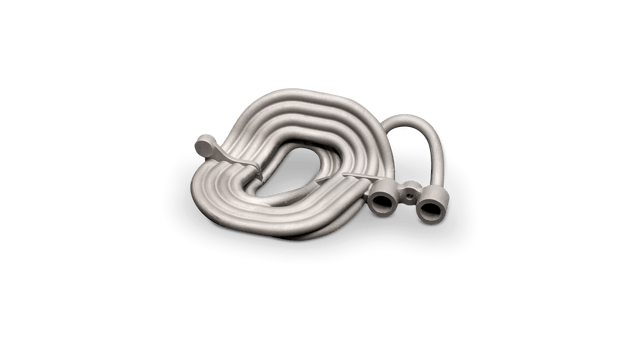
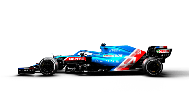
Alpine F1 Team turned to metal additive manufacturing (AM) to push the performance of its car by producing a titanium hydraulic accumulator with complete functionality in a minimized footprint. With years of collaborative supply and development with 3D Systems, Alpine F1 Team selected 3D Systems’ direct metal printing (DMP) technology to produce the complex part, and relied on 3D Systems’ expertise and proprietary cleaning processes to ensure optimal quality.
“Beyond the necessary accuracy of the part itself, we had very strict fluid cleanliness requirements for the inverter coil that could only be achieved by partnering with 3D Systems. Their proprietary cleaning process has a proven track record in high performance applications for delivering particle-free components, even on challenging internal channels.”
– Pat Warner, Advanced Digital Manufacturing Manager, Alpine F1 Team
PUSH PERFORMANCE WITH ADVANCED DESIGN AND MANUFACTURING
Alpine F1 Team is continually improving its car, working in very short iteration cycles to advance and refine performance as much as possible. Constant challenges include working within the limited space available, keeping part weights as low as possible, and adhering to evolving regulation constraints.
Experts within 3D Systems’ Application Innovation Group (AIG) provided Alpine F1 Team with the know-how to make titanium production possible for a complex coiled component with a challenging, function-driven internal geometry. Additive manufacturing offers a unique opportunity to overcome the challenges of fast-paced innovation by supplying highly complex parts with short lead times. For parts like Alpine F1 Team’s hydraulic accumulator, additional AM expertise was required for a successful part due to the level of design complexity and strict requirements for cleanliness.
Additive manufacturing enabled the Alpine F1 Team to maximize the length of the dampening coil while packaging complete functionality within a restricted space.
The Solution
01 Packaging Complex Functionality in a Limited Space
For the accumulator, specifically a rear heave fluid inerter coil, Alpine F1 Team designed a hard-line damper, which is part of a rear heave damper in the rear suspension system inside the gearbox main case. A long, rigid piece of tubing, the accumulator stores and releases energy in order to average out pressure fluctuations. As such, the performance of the line damper is correlated to its internal volume, and thus the length of the component.
Additive manufacturing enabled the Alpine F1 Team to maximize the length of the dampening coil while packaging complete functionality within a restricted space. According to Pat Warner, Advanced Digital Manufacturing Manager at Alpine F1 Team, the final design would be impossible to produce using any other method: “We designed this part to be as volumetrically efficient as possible, and to share wall thickness between adjacent tubes. Achieving this volume is only possible with AM.”
The final titanium dampening coil was produced using 3D Systems’ DMP Flex 350, a high-performance metal AM system featuring best-in-class oxygen levels (<25 ppm) and an inert printing atmosphere. The unique system architecture of 3D Systems’ DMP machines ensures exceptionally strong and accurate parts with high chemical purity, and the repeatability needed for production parts.
02 Part Cleanliness for Flawless Performance
During operation the dampening coil is filled with fluid and averages out pressure fluctuations within the system by absorbing and releasing energy. In order to function properly, the fluid has a specification for cleanliness to avoid contamination. Using metal AM to design and produce this component offered considerable benefits in terms of functionality, integration into the larger system, and weight reduction, yet the team faced a challenge when it came to complete powder removal from the internal channels.
To achieve thorough material evacuation on these complex metal prints 3D Systems’ AIG contributed its vast process knowledge to apply a proprietary cleaning protocol that has been successfully used on to tens of thousands of parts, and ensures particle-free titanium components. For customers who plan to adopt metal AM and require the highest degree of part cleanliness for internal channels, 3D Systems has an established protocol to transfer this know-how to new facilities.
Alpine F1 Team works in very short iteration cycles to advance and refine the performance of its car as much as possible.
03 Quality Metal Workflow
3D Systems’ complete metal AM solution goes beyond its leading expertise and metal printing platform to include carefully developed and optimized materials and 3DXpert software. 3DXpert is an all-in-one software for preparing, optimizing, and managing the metal printing workflow.
Alpine F1 Team selected LaserForm Ti Gr23 (A) material for its accumulator, citing high strength and the ability to accurately produce thin wall sections as the reasons for its choice. All LaserForm materials have specific, extensively developed print parameters within 3DXpert that package the expertise of 3D Systems’ engineers within the workflow for the highest quality results.
04 Expert Consultation
Alpine F1 Team leveraged 3D Systems’ design for additive manufacturing expertise to accelerate its path forward and advance its success with guidance on optimum build orientation, achievable wall thicknesses, and how to share walls between adjacent wall sections, as well as its post-processing expertise. As a consistent co-developer of innovative and industry-first solutions, 3D Systems’ Application Innovation Group has a breadth and depth of experience in transitioning applications from concepts to scaled manufacturing.
3D Systems is partner to hundreds of critical applications across industries where quality and performance are paramount. 3D Systems’ systematized approach to scaling from prototyping to production ensures a streamlined path to qualified AM parts, and the AM leader also offers technology transfer to help customers successfully adopt additive manufacturing within their own facilities.
Following the success of Alpine F1 Team’s titanium printed accumulator, Warner says the team was encouraged to pursue more complex suspension components the following year.
Product: Geomagic Design X Industry: Automotive and Transportation
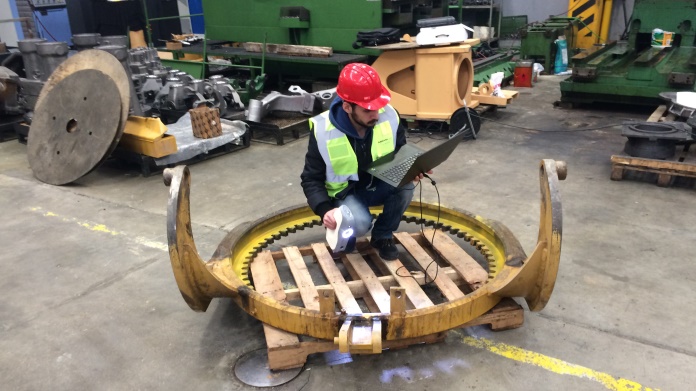
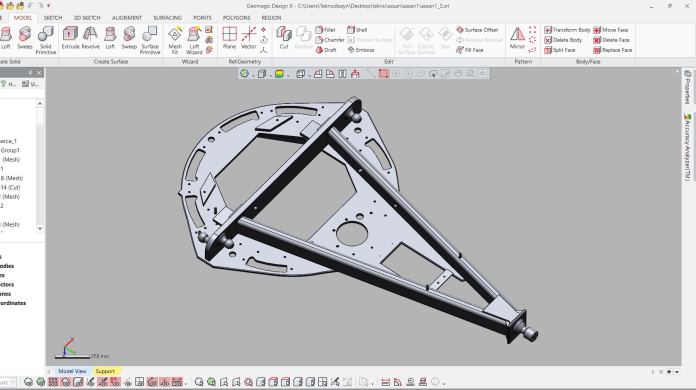
In order to retrofit a construction machine, two of its parts were 3D scanned, reverse engineered and milled anew.
Artec’s Gold Partner in Turkey Teknodizayn has successfully completed a project for replacing old parts of a construction machine with new ones, milled from 3D models that were made with Artec Eva, a high-precision portable 3D scanner for large objects.
The job was commissioned by Assan ASP, a well-known international manufacturer and distributor of construction machine spare parts.
Normally it would take Assan ASP a couple of weeks to measure and draw these parts, and some of the elements were quite difficult to measure accurately with traditional methods.
After a demonstration by Teknodizayn, Assan ASP managers saw that it is significantly easier and much faster to work with Artec 3D scanning solutions and Geomagic reverse engineering software on cases like this.
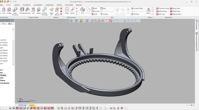
The task was to duplicate two independent parts of a construction machine (drawbar & yoke assembly and circle assembly) for future use.
The task was to duplicate two independent parts of a construction machine (drawbar & yoke assembly and circle assembly) for future use. The parts needed to be accurately manufactured from the data obtained during 3D scanning and then fitted to the same type of construction machine.
“As we know, Artec 3D scanners are the best to use in situations where there is a big part that needs to be scanned in a location where conditions are difficult. This was exactly this kind of situation,” says Ali Can Boysan, Sales & Technical Support Manager at Teknodizayn.
Ali had to scan on the premises of the manufacturing facility, wearing special safety equipment. He used the Artec Eva scanner along with the Artec battery pack as there was no immediate access to the mains power supply.
Ali Can Boysan scans the drawbar & yoke assembly with Artec Eva.
“The freedom of movement with the Artec battery pack was a huge advantage, I walked around the parts freely,” says Ali.
The parts featured some shiny and metallic surfaces, so those areas needed to be sprayed before scanning.
“Artec Eva was the suitable scanner for this job as the parts were very big and the accuracy required was in the range of Artec Eva’s accuracy,” says Ali. “The scanning was pretty fast and easy considering that those were huge parts, around 3 meters.”
Scanning the circle assembly with Artec Eva.
Each part took 30-40 minutes to scan in detail (including the top and bottom areas).
“Those were very fast scan sessions,” says Ali. “No other scanner can measure such big parts this accurately and fast.”
Once he was done with the scanning, Ali transferred the data to his computer at the Teknodizayn office. Post-processing each part in Artec Studio 11 3D imaging software took around 4-5 hours. There were numerous scans from different angles on both top and bottom sides of the parts, which added up to a large amount of data.
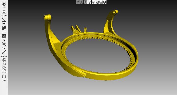
The .stl model of the drawbar & yoke assembly in Artec Studio 11.
The data was processed manually. First the unnecessary parts of the scans were erased, and then the scans were aligned using the quick and simple point to point alignment algorithm. Then Global Registration with Texture and Geometry was applied, which resulted in a dense and accurate point cloud that needed to be meshed. The next step was Sharp Fusion with the best possible resolution, creating .stl mesh models ready for reverse engineering.
The .stl model of the circle assembly in Artec Studio 11.
The files were exported to Geomagic Design X reverse engineering software. “This is no doubt the best, fastest and easiest program among its competitors,” says Ali. “Our reverse engineering specialist first auto-regioned the parts and then aligned them to coordinate planes. Later he parametrically drew the solid models accurately, feature by feature. After 7-8 hours of working on each part, the solid models were ready to be manufactured directly.”
The drawbar & yoke assembly in Geomagic Design X.
The circle assembly in Geomagic Design X.
The manufactured parts achieved the exact precision required. They were installed and tested on a working construction machine, proving to fit very well. Assan ASP were impressed with the results and bought an Artec Eva, Space Spider and Geomagic for SOLIDWORKS CAD bundle to improve their traditional workflow and use the technology in future R&D.
Want this delivered to your inbox?
Be the first to hear about new offers and updates from Artec 3D.Email *Sign me up to the Artec 3D newsletterArtec 3D may send me offers and promotions
Product: Artec Leo Industry: Automotive and Transportation
Every time forensic accident reconstruction expert Jarrod Carter, Ph.D., steps up to a twisted wreck, he sees a book of stories waiting to be told: how fast was the car moving when it slammed into the bridge? How many seconds before impact did the driver hit the brakes? Was everyone inside wearing their seat belts? And how well did the car’s safety features protect its occupants?
When Carter and his team at Origin Forensics are called upon to help tell the story behind a wreck, they collect a wide variety of data, including 3D site models from drone photos and tripod-based laser scanners, police reports, scene photos or videos from police or others, surveillance footage, stop-light camera video, dash cam video, and event data recorder (EDR, a.k.a. the car’s “black box”) data.
These varied sources offer up a broad spectrum of details from the seconds leading up to and including the crash: brake usage, accelerator application, steering wheel angle, lateral/longitudinal acceleration, roll rate, engine RPMs, gear positions, and more.
A recent addition to their storytelling toolbox is the Artec Leo.
Origin uses the Leo, a wireless handheld 3D scanner unlike any other, to tell the story behind the twisted metal that is a wrecked vehicle. Based on experience, they have found that the Leo can faithfully generate a digital twin of a vehicle’s exterior or interior in under an hour, from bumper to bumper, with submillimeter accuracy.
Artec Studio software screenshot showing the Leo scan of the 2014 Dodge Charger
In the past, as part of their push to create digital twins of wrecked vehicles, they used a tripod‑mounted 3D laser scanner. The scanning process entailed physically repositioning the scanner numerous times around the vehicle, at multiple elevations, inside and out, to record as much detail as possible.
And, even with all the repositioning, the detail, while tremendously better than the plumb bob and tape measure method Carter used at the beginning of his career, was still lacking in the qualities necessary to create a convincing digital twin.
Another significant problem with the tripod-based laser scanner workflow was time. Each scan with a tripod-based scanner takes several minutes, not including the time associated with repositioning. A detailed scan of a vehicle could easily take an hour and, in some cases, as much as two or three hours.
A brief window of time to scan the entire vehicle
When Carter and his team get down to work, they generally have a window of four to eight hours of access to a vehicle, and scanning is not their only agenda item. And, as a rule, they treat their time with the vehicle as though it is the last time they, or anyone, will ever see it. So, any time savings afforded during the scanning phase provides extra breathing room to ensure that the inspection is as complete as possible.
“This (the issue of time) is one of the main reasons I kept my eye out for a better solution than our tripod‑based laser scanner. I was looking for speed and flexibility, which Leo gives us, especially since it has no cables or attached computer to slow you down. I no longer feel as though the rest of the inspection is being rushed so that I can make sufficient time to scan the vehicle,” Carter said.
Jarrod Carter Ph.D., scanning a Dodge Minivan with Artec Leo (at Insurance Auto Auction in Puyallup, WA)
“Because the vehicle is at the very center of our work, it is important to spend enough time gathering the data needed for its digital twin, even when that took us a lot longer than it does today. Now, with Leo, we collect the data for the vehicle’s digital twin so much faster. And I can use the touchscreen on the back to check the quality of the 3D mesh it’s making, the texture being captured, to make sure I have what I need before I leave,” said Carter.
“If I missed some aspect of the vehicle or didn’t get the detail I wanted in an area, I can easily rescan the bit I’m interested in with a wave of the scanner. It’s not like in the past with our tripod-based laser scanning workflow, where we’d have to wait till we got back to the office and started processing the data before we realized that some texture or geometry was captured less than ideally. With Leo, when we walk away from the vehicle, we’re confident it’s all there.”
The crucial need for extensive, true-to-life textures
As it relates to the texture data, Carter expressed high praise for the Leo’s capability, “What we weren’t expecting with Leo was the fidelity of the texture information it captures. The color and surface details appear photorealistic, or very nearly so. And the texture is not isolated to the individual points in the point cloud, like with a tripod-based scanner.”
“Instead, the texture fills the spaces between those points. A side benefit of filling in the gaps comes when you examine the vehicle from perspectives you didn’t consider when you were at the inspection. Now I’m not limited by the photos I took at the inspection. I can generate, on demand, what look like inspection photos of different aspects of the vehicle.”
Carter continued, “With Leo, we get highly accurate scans that provide more than enough geometry data for any analysis we need to conduct. And then you add in the photo texture to make it real. I remember the first time I zoomed in on the model of a vehicle we captured with our Leo. It was phenomenal. It looked exactly like the vehicle, which is what you want with a digital twin. We weren’t able to generate such high-fidelity models in the past. Not even close.”
Artec Studio screenshot showing the Leo scan of the Dodge Minivan
Having a digital twin of the vehicle that’s lifelike down to the smallest detail has become an expectation for Carter and his team since they started using their Leo. “When we sit down to go through the Leo scans in Artec Studio, it’s like being right there alongside the vehicle exactly as it looked during the inspection. We can visualize the evidence from any perspective we want, and we can measure it with exceptional accuracy,” Carter said.
Inspecting vehicle damage in Artec Studio
Carter explained one way they use the data from their Leo, “Once we compile the scans of a damaged vehicle, we align any undamaged portions of that vehicle with a 3D model or scan dataset of a similar undamaged vehicle. The comparison of damaged to undamaged allows us to determine the extent of crush on the damaged vehicle, which then provides a springboard for determining the direction and magnitude of collision forces, as well as how much energy was absorbed in the collision.”
“We can estimate change-in-velocity (delta-V) from absorbed energy and impact speed with enough other evidence. Additionally, we can use the comparison between the damaged and undamaged vehicles alongside our collision analysis to assist other experts who are trying to determine how the occupants were injured, and still other experts who are assessing the potential that some aspect of the vehicle’s design or manufacturing caused or enhanced those injuries.”
From 3D scan to biomechanical injury analysis
Origin Forensics also uses the data from Leo for biomechanical injury analysis. Here Carter and his team translate the outer crash event to the events involving the occupants inside the vehicle. A key aspect of the analysis focuses on determining how the occupants were interacting with the interior features of the car from the moment of impact onwards.
In Carter’s words, “We match up the occupant’s injuries to the elements of the passenger compartment that caused them, and determine whether any of the safety features there failed to perform as expected, whether that’s airbags, seat belts, or something else that was designed to mitigate injury. Could something have been designed or manufactured differently to prevent those injuries? We analyze every possible scenario, from beginning to end.”
Carter and Rothwell reviewing Leo scan data of the 2014 Dodge Charger in Artec Studio
During initial consultations with a client, in-person or over the web, Carter can share his screen and bring up the digital twin his team generated with their Leo, pointing out and explaining any relevant details.
Inspecting the Charger’s crush deformation patterns using Artec Studio’s surface distance mapping feature
As Carter explained, “Navigating around such a detailed 3D model provides a valuable adjunct to any 2D photos of the vehicle, which are frozen in time from the chosen perspective. Often the client will be curious about a specific aspect of the vehicle and we can take them right there and show it to them as though we were standing next to the vehicle or looking at a photo taken from that particular perspective.”
Using Leo scans for comprehensive vehicle damage reports
Following initial consultations with a client, there may be a need to submit a written report or to testify in deposition or trial. Generating exhibits that help the report reader or jury member understand the nature and extent of the damage sustained by an involved vehicle, or vehicles, is frequently an integral part of the process. And the 3D models generated from Leo scans provide the assets needed to create compelling visual exhibits.
Forensic Technician Kyle Rothwell, Origin Forensics’ in-house expert on Leo, described how he processes the Leo scans in Artec Studio software: “After importing our Leo scans, first I run Global Registration on a group of scans, then Outlier Removal on each of the groups, after which I align them.”
Rothwell processing the Leo scans of the 2014 Dodge Charger
“Then I clean up any stray geometry data, such as bits of glass, dirt, asphalt, etc. Once the raw data is registered, aligned, and cleaned up, I orient the scans to set the ground plane and rotate the object so that the right side view = the right side of the vehicle.”
Rothwell continued, “Then I run a Sharp Fusion, followed by a Fast Mesh Simplification. For a vehicle, a mesh density of about 2 million to 5 million triangles is appropriate for what we need. From there, I will apply the texture information for export and select the reduced glare. I normally use an 8K texture map to retain the smaller details. Then the model is ready for export, usually in .OBJ format with .PNG texture.”
3D digital twins of vehicles: even better than the real thing
Even though the majority of the cases that Carter and his team handle are settled out of court, or dismissed, and therefore never go to trial, if they do, their Leo has given them the ability to do what they always dreamed of: to put a true-to-life, virtual representation of the vehicle right in front of the jury.
“It’s even better than being up close with the vehicle itself, since with the digital twin, I can zoom in, rotate it however I want, and show everyone any part of the damage from any angle or magnification they’d like. And all of this evidence is fresh from the accident, so it represents what I saw during my inspection,” said Carter.
Preparing for inspection in Artec Studio: merging the Charger scan with an exemplar 3D model of the same vehicle
“In the not-too-distant future,” Carter hinted, “it may be commonplace that juries will have their own monitor or be wearing VR goggles when such exhibits are presented, which would make the impact of the Leo scan data all the more unforgettable. We could take them on a guided tour around or inside a vehicle, calling their attention to key aspects on demand.”
“In the past, we would have to bring the actual car to the courthouse and take the jury out to see it, which is an expensive operation with no guarantee the court will even allow it. With the data we generate from our Leo, now we can bring the car to the courtroom and let the jurors walk around it virtually.”
Using Artec Studio’s surface distance mapping to visually inspect the crashed Charger’s damage
So, what led Carter to the Artec Leo? While searching online and comparing all the handheld 3D scanners available on the market, Carter found the YouTube channel of Artec Ambassador Digitize Designs. From there, he reached out and spoke with Bo Helmrich, the company’s 3D Scanning Expert, who introduced him to the Artec Leo by sending videos of the scanning process and example data from a vehicle scan.
To show them how effectively the Leo would meet their needs, for the demo, Helmrich scanned the entire exterior of his Toyota Highlander with Leo, which took 32 minutes from start to finish. 90 minutes later and the scans were processed and ready to go. Carter remembered his first impressions of the 3D model he received:
“I was just blown away by the geometric detail, as well as the textures I was looking at because they’re massively important in the work we do. Now, without the quality of the underlying 3D data being so high, the textures wouldn’t be nearly as effective. Because both the textures and the 3D data contextualize each other.”
Carter explained further, “If for any reason the polygonal mesh is out of whack, distorted, or warped, even in the least, no amount of amazing texture is going to save that. Fortunately, Leo delivers brilliant results in both categories. We saw it then and we see it in every single project we use it for today.”
Learning to use the Leo, from unboxing to scanning in minutes
After purchasing their Leo, Carter and his team were given remote training on how to use the scanner and Artec Studio software. Rothwell commented on his experience with this:
“Learning how to use our Leo on smaller objects like a Pelican case was a joy. Right out of the box, Leo was ready to go and generating detailed models in just a few minutes. Scanning larger objects was a bit more challenging at first, so I found a different approach.”
He elaborated, “I learned that it worked best when I broke down the project into smaller chunks, which meant scanning each vehicle in sections and then loading them one by one in Artec Studio. Now we have consistent and accurate results every time.”
When asked about the difference in their work that Leo has made, Rothwell said, “When I think back to how we were scanning before our Leo came onboard, there really is no comparison.”
Forensic Technician Kyle Rothwell scanning a vehicle with Artec Leo
He continued, “The Leo is on an entirely different level. Operationally, it’s the feedback you get while scanning (real-time review), the ability to capture fine details, and the quality of color texture information that absolutely set the Leo apart.”
With their extensive engineering backgrounds and reconstruction experience, Carter and his team are regularly called to work on accidents that require a deep level of understanding of the physics involved in a crash. Further, they frequently extend their analysis to evaluating the injuries sustained by a vehicle’s occupants.
That’s the reason why big names such as Chrysler, Ford Motors, Honda, Jeep, Nissan, Progressive, Safeco, Toyota, and other companies and agencies across the United States regularly turn to Origin Forensics. Their in-depth investigations, detailed reports, and honest consultations bring existing clients back, and drive frequent referrals to new clients.
Origin Forensics’ guiding motto is “Veritas, Fidelitas, Claritas” (Truth, Faithfulness, Clarity). Their motto defines their mission, which is to discover the truth, while faithfully representing the evidence using the latest and best technologies, and then presenting their findings to clients, judges, and juries with the utmost clarity.
Carter explained why Leo is essential to their mission, “I want to push the boundaries of what’s possible in forensic accident reconstruction, and that requires me to always be on the lookout for the best technologies, so we can provide exceptional services and solutions for our clients. That’s why I chose the Artec Leo. It gives us that edge beyond anything else on the market.”


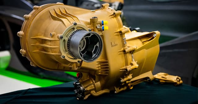
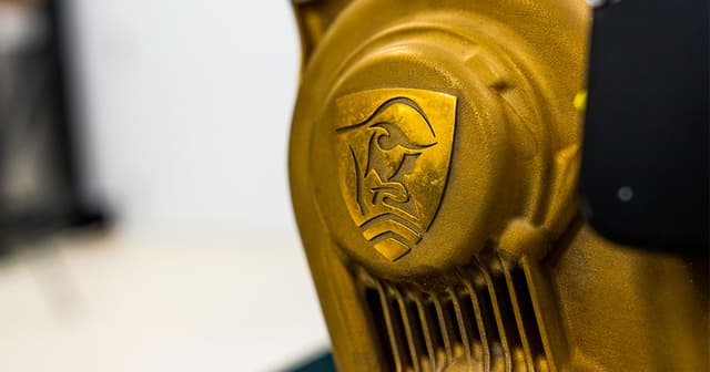
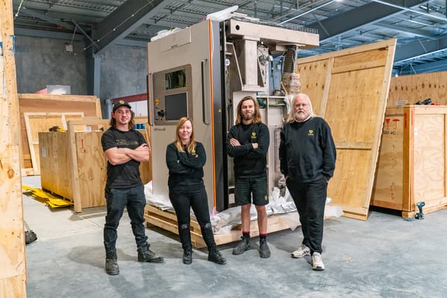
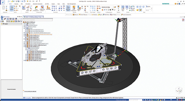

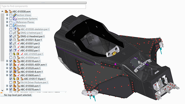
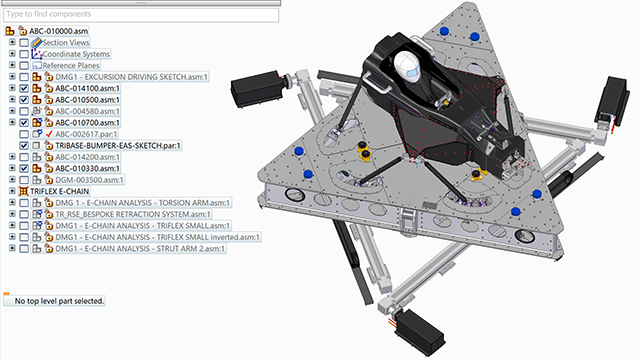
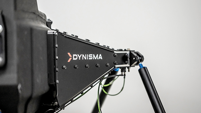
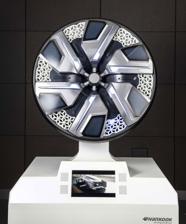
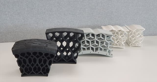
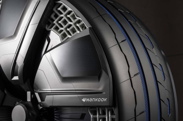
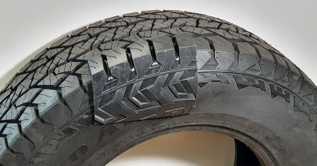
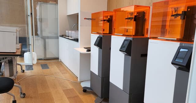
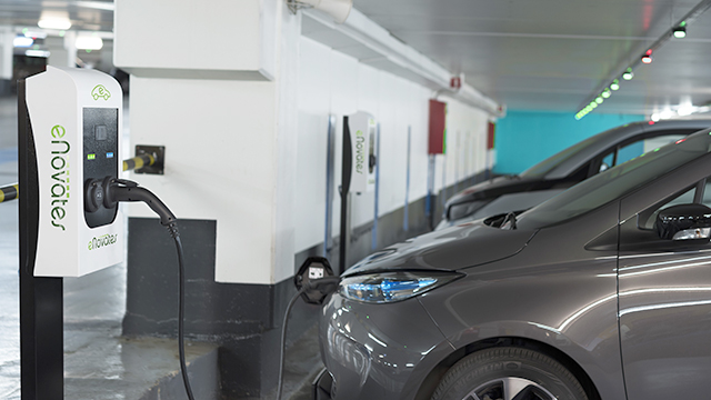
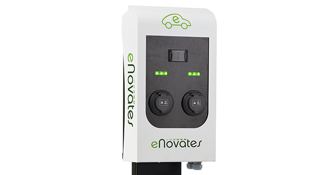
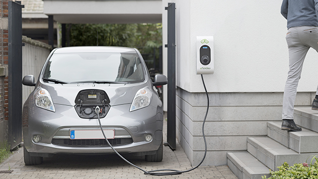
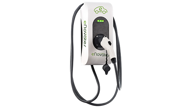
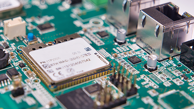


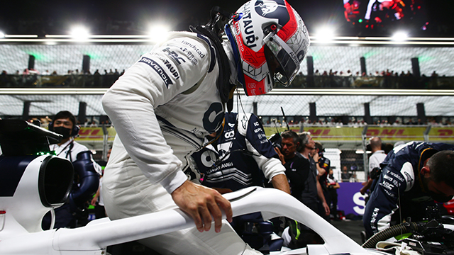
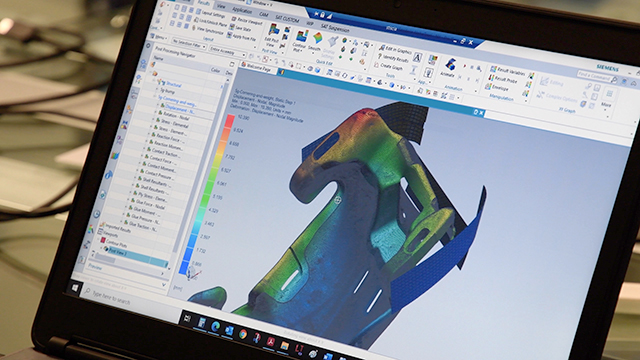
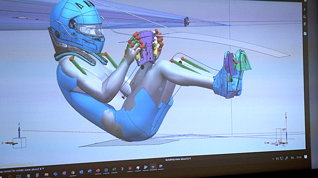
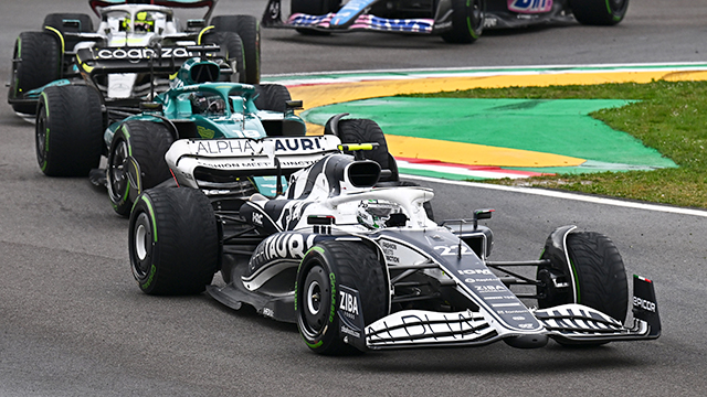 Zooming around over 300km/h during a normal F1 race, drivers experience up to four or five lateral G’s routinely under braking and cornering and during acceleration on the long stretches.
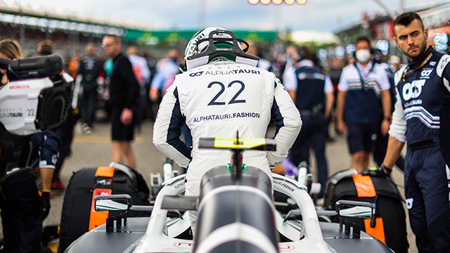
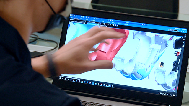 Data is king: any piece of information the team can analyze will help them understand the performance behavior of the new car.