3D scanning for traffic accident reconstruction: How Origin Forensics uses Artec Leo

Product: Artec Leo
Industry: Automotive and Transportation

Every time forensic accident reconstruction expert Jarrod Carter, Ph.D., steps up to a twisted wreck, he sees a book of stories waiting to be told: how fast was the car moving when it slammed into the bridge? How many seconds before impact did the driver hit the brakes? Was everyone inside wearing their seat belts? And how well did the car’s safety features protect its occupants?

When Carter and his team at Origin Forensics are called upon to help tell the story behind a wreck, they collect a wide variety of data, including 3D site models from drone photos and tripod-based laser scanners, police reports, scene photos or videos from police or others, surveillance footage, stop-light camera video, dash cam video, and event data recorder (EDR, a.k.a. the car’s “black box”) data.

These varied sources offer up a broad spectrum of details from the seconds leading up to and including the crash: brake usage, accelerator application, steering wheel angle, lateral/longitudinal acceleration, roll rate, engine RPMs, gear positions, and more.

A recent addition to their storytelling toolbox is the Artec Leo.

Origin uses the Leo, a wireless handheld 3D scanner unlike any other, to tell the story behind the twisted metal that is a wrecked vehicle. Based on experience, they have found that the Leo can faithfully generate a digital twin of a vehicle’s exterior or interior in under an hour, from bumper to bumper, with submillimeter accuracy.

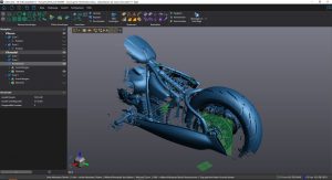
Artec Studio software screenshot showing the Leo scan of the 2014 Dodge Charger

In the past, as part of their push to create digital twins of wrecked vehicles, they used a tripod‑mounted 3D laser scanner. The scanning process entailed physically repositioning the scanner numerous times around the vehicle, at multiple elevations, inside and out, to record as much detail as possible.

And, even with all the repositioning, the detail, while tremendously better than the plumb bob and tape measure method Carter used at the beginning of his career, was still lacking in the qualities necessary to create a convincing digital twin.

Another significant problem with the tripod-based laser scanner workflow was time. Each scan with a tripod-based scanner takes several minutes, not including the time associated with repositioning. A detailed scan of a vehicle could easily take an hour and, in some cases, as much as two or three hours.

A brief window of time to scan the entire vehicle

When Carter and his team get down to work, they generally have a window of four to eight hours of access to a vehicle, and scanning is not their only agenda item. And, as a rule, they treat their time with the vehicle as though it is the last time they, or anyone, will ever see it. So, any time savings afforded during the scanning phase provides extra breathing room to ensure that the inspection is as complete as possible.

“This (the issue of time) is one of the main reasons I kept my eye out for a better solution than our tripod‑based laser scanner. I was looking for speed and flexibility, which Leo gives us, especially since it has no cables or attached computer to slow you down. I no longer feel as though the rest of the inspection is being rushed so that I can make sufficient time to scan the vehicle,” Carter said.

Jarrod Carter Ph.D., scanning a Dodge Minivan with Artec Leo (at Insurance Auto Auction in Puyallup, WA)

“Because the vehicle is at the very center of our work, it is important to spend enough time gathering the data needed for its digital twin, even when that took us a lot longer than it does today. Now, with Leo, we collect the data for the vehicle’s digital twin so much faster. And I can use the touchscreen on the back to check the quality of the 3D mesh it’s making, the texture being captured, to make sure I have what I need before I leave,” said Carter.

If I missed some aspect of the vehicle or didn’t get the detail I wanted in an area, I can easily rescan the bit I’m interested in with a wave of the scanner. It’s not like in the past with our tripod-based laser scanning workflow, where we’d have to wait till we got back to the office and started processing the data before we realized that some texture or geometry was captured less than ideally. With Leo, when we walk away from the vehicle, we’re confident it’s all there.”

The crucial need for extensive, true-to-life textures

As it relates to the texture data, Carter expressed high praise for the Leo’s capability, “What we weren’t expecting with Leo was the fidelity of the texture information it captures. The color and surface details appear photorealistic, or very nearly so. And the texture is not isolated to the individual points in the point cloud, like with a tripod-based scanner.”

“Instead, the texture fills the spaces between those points. A side benefit of filling in the gaps comes when you examine the vehicle from perspectives you didn’t consider when you were at the inspection. Now I’m not limited by the photos I took at the inspection. I can generate, on demand, what look like inspection photos of different aspects of the vehicle.”

Carter continued, “With Leo, we get highly accurate scans that provide more than enough geometry data for any analysis we need to conduct. And then you add in the photo texture to make it real. I remember the first time I zoomed in on the model of a vehicle we captured with our Leo. It was phenomenal. It looked exactly like the vehicle, which is what you want with a digital twin. We weren’t able to generate such high-fidelity models in the past. Not even close.”

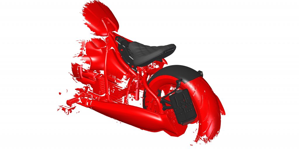
Artec Studio screenshot showing the Leo scan of the Dodge Minivan

Having a digital twin of the vehicle that’s lifelike down to the smallest detail has become an expectation for Carter and his team since they started using their Leo. “When we sit down to go through the Leo scans in Artec Studio, it’s like being right there alongside the vehicle exactly as it looked during the inspection. We can visualize the evidence from any perspective we want, and we can measure it with exceptional accuracy,” Carter said.

Inspecting vehicle damage in Artec Studio

Carter explained one way they use the data from their Leo, “Once we compile the scans of a damaged vehicle, we align any undamaged portions of that vehicle with a 3D model or scan dataset of a similar undamaged vehicle. The comparison of damaged to undamaged allows us to determine the extent of crush on the damaged vehicle, which then provides a springboard for determining the direction and magnitude of collision forces, as well as how much energy was absorbed in the collision.”

“We can estimate change-in-velocity (delta-V) from absorbed energy and impact speed with enough other evidence. Additionally, we can use the comparison between the damaged and undamaged vehicles alongside our collision analysis to assist other experts who are trying to determine how the occupants were injured, and still other experts who are assessing the potential that some aspect of the vehicle’s design or manufacturing caused or enhanced those injuries.”

From 3D scan to biomechanical injury analysis

Origin Forensics also uses the data from Leo for biomechanical injury analysis. Here Carter and his team translate the outer crash event to the events involving the occupants inside the vehicle. A key aspect of the analysis focuses on determining how the occupants were interacting with the interior features of the car from the moment of impact onwards.

In Carter’s words, “We match up the occupant’s injuries to the elements of the passenger compartment that caused them, and determine whether any of the safety features there failed to perform as expected, whether that’s airbags, seat belts, or something else that was designed to mitigate injury. Could something have been designed or manufactured differently to prevent those injuries? We analyze every possible scenario, from beginning to end.”

Carter and Rothwell reviewing Leo scan data of the 2014 Dodge Charger in Artec Studio

During initial consultations with a client, in-person or over the web, Carter can share his screen and bring up the digital twin his team generated with their Leo, pointing out and explaining any relevant details.

Inspecting the Charger’s crush deformation patterns using Artec Studio’s surface distance mapping feature

As Carter explained, “Navigating around such a detailed 3D model provides a valuable adjunct to any 2D photos of the vehicle, which are frozen in time from the chosen perspective. Often the client will be curious about a specific aspect of the vehicle and we can take them right there and show it to them as though we were standing next to the vehicle or looking at a photo taken from that particular perspective.”

Using Leo scans for comprehensive vehicle damage reports

Following initial consultations with a client, there may be a need to submit a written report or to testify in deposition or trial. Generating exhibits that help the report reader or jury member understand the nature and extent of the damage sustained by an involved vehicle, or vehicles, is frequently an integral part of the process. And the 3D models generated from Leo scans provide the assets needed to create compelling visual exhibits.

Forensic Technician Kyle Rothwell, Origin Forensics’ in-house expert on Leo, described how he processes the Leo scans in Artec Studio software: “After importing our Leo scans, first I run Global Registration on a group of scans, then Outlier Removal on each of the groups, after which I align them.”

Rothwell processing the Leo scans of the 2014 Dodge Charger

“Then I clean up any stray geometry data, such as bits of glass, dirt, asphalt, etc. Once the raw data is registered, aligned, and cleaned up, I orient the scans to set the ground plane and rotate the object so that the right side view = the right side of the vehicle.”

Rothwell continued, “Then I run a Sharp Fusion, followed by a Fast Mesh Simplification. For a vehicle, a mesh density of about 2 million to 5 million triangles is appropriate for what we need. From there, I will apply the texture information for export and select the reduced glare. I normally use an 8K texture map to retain the smaller details. Then the model is ready for export, usually in .OBJ format with .PNG texture.”

3D digital twins of vehicles: even better than the real thing

Even though the majority of the cases that Carter and his team handle are settled out of court, or dismissed, and therefore never go to trial, if they do, their Leo has given them the ability to do what they always dreamed of: to put a true-to-life, virtual representation of the vehicle right in front of the jury.

“It’s even better than being up close with the vehicle itself, since with the digital twin, I can zoom in, rotate it however I want, and show everyone any part of the damage from any angle or magnification they’d like. And all of this evidence is fresh from the accident, so it represents what I saw during my inspection,” said Carter.

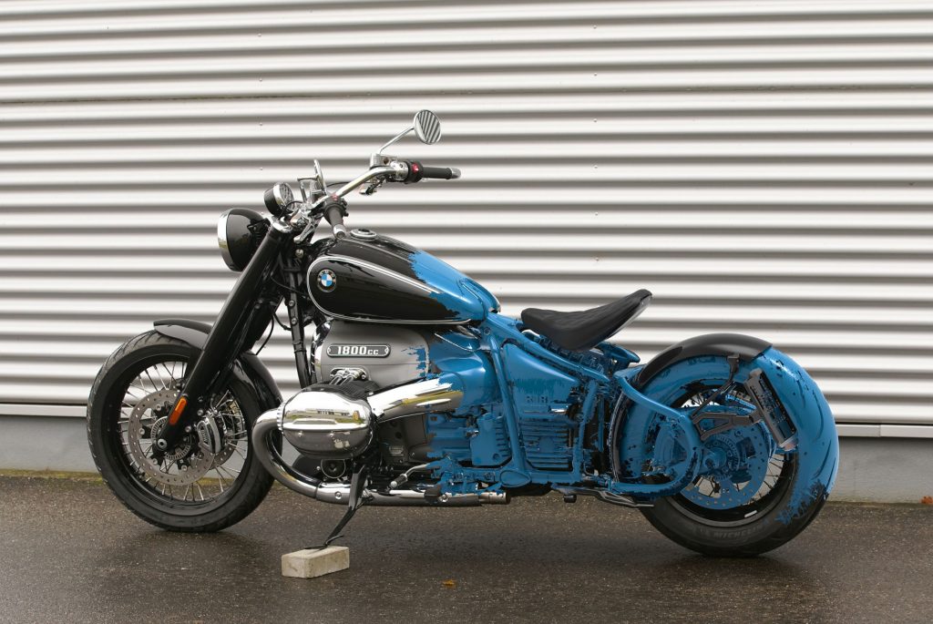
Preparing for inspection in Artec Studio: merging the Charger scan with an exemplar 3D model of the same vehicle

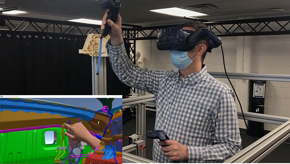
“In the not-too-distant future,” Carter hinted, “it may be commonplace that juries will have their own monitor or be wearing VR goggles when such exhibits are presented, which would make the impact of the Leo scan data all the more unforgettable. We could take them on a guided tour around or inside a vehicle, calling their attention to key aspects on demand.”

“In the past, we would have to bring the actual car to the courthouse and take the jury out to see it, which is an expensive operation with no guarantee the court will even allow it. With the data we generate from our Leo, now we can bring the car to the courtroom and let the jurors walk around it virtually.”

Using Artec Studio’s surface distance mapping to visually inspect the crashed Charger’s damage

So, what led Carter to the Artec Leo? While searching online and comparing all the handheld 3D scanners available on the market, Carter found the YouTube channel of Artec Ambassador Digitize Designs. From there, he reached out and spoke with Bo Helmrich, the company’s 3D Scanning Expert, who introduced him to the Artec Leo by sending videos of the scanning process and example data from a vehicle scan.

To show them how effectively the Leo would meet their needs, for the demo, Helmrich scanned the entire exterior of his Toyota Highlander with Leo, which took 32 minutes from start to finish. 90 minutes later and the scans were processed and ready to go. Carter remembered his first impressions of the 3D model he received:

“I was just blown away by the geometric detail, as well as the textures I was looking at because they’re massively important in the work we do. Now, without the quality of the underlying 3D data being so high, the textures wouldn’t be nearly as effective. Because both the textures and the 3D data contextualize each other.”

Carter explained further, “If for any reason the polygonal mesh is out of whack, distorted, or warped, even in the least, no amount of amazing texture is going to save that. Fortunately, Leo delivers brilliant results in both categories. We saw it then and we see it in every single project we use it for today.”

Learning to use the Leo, from unboxing to scanning in minutes

After purchasing their Leo, Carter and his team were given remote training on how to use the scanner and Artec Studio software. Rothwell commented on his experience with this:

“Learning how to use our Leo on smaller objects like a Pelican case was a joy. Right out of the box, Leo was ready to go and generating detailed models in just a few minutes. Scanning larger objects was a bit more challenging at first, so I found a different approach.”

He elaborated, “I learned that it worked best when I broke down the project into smaller chunks, which meant scanning each vehicle in sections and then loading them one by one in Artec Studio. Now we have consistent and accurate results every time.”

When asked about the difference in their work that Leo has made, Rothwell said, “When I think back to how we were scanning before our Leo came onboard, there really is no comparison.”

Forensic Technician Kyle Rothwell scanning a vehicle with Artec Leo

He continued, “The Leo is on an entirely different level. Operationally, it’s the feedback you get while scanning (real-time review), the ability to capture fine details, and the quality of color texture information that absolutely set the Leo apart.”

With their extensive engineering backgrounds and reconstruction experience, Carter and his team are regularly called to work on accidents that require a deep level of understanding of the physics involved in a crash. Further, they frequently extend their analysis to evaluating the injuries sustained by a vehicle’s occupants.

That’s the reason why big names such as Chrysler, Ford Motors, Honda, Jeep, Nissan, Progressive, Safeco, Toyota, and other companies and agencies across the United States regularly turn to Origin Forensics. Their in-depth investigations, detailed reports, and honest consultations bring existing clients back, and drive frequent referrals to new clients.

Origin Forensics’ guiding motto is “Veritas, Fidelitas, Claritas” (Truth, Faithfulness, Clarity). Their motto defines their mission, which is to discover the truth, while faithfully representing the evidence using the latest and best technologies, and then presenting their findings to clients, judges, and juries with the utmost clarity.

Carter explained why Leo is essential to their mission, “I want to push the boundaries of what’s possible in forensic accident reconstruction, and that requires me to always be on the lookout for the best technologies, so we can provide exceptional services and solutions for our clients. That’s why I chose the Artec Leo. It gives us that edge beyond anything else on the market.”

Artec Space Spider meets Car SOS to restore one of Britain’s best-selling auto classics

Product: Artec 3D Space Spider
Industry: Automotive and Transportation

Car SOS TV hosts (left and in the center) and the lucky owner of the restored Ford Cortina Mark III after the grand reveal

Meet Bobby

When 54-year-old Sikh historian and writer Bobby Singh bought his Ford Cortina Mark III XL back in 1999, he didn’t think it would take long for him and his 1970s British classic car to hit the road again.

But his plans came to a screeching halt in 2002 when Bobby, then in his mid-thirties, suffered a stroke. Not long after, in 2008, his family business collapsed, and then Bobby was diagnosed with heart disease. Throughout this devastating chain of events, Bobby’s family lost everything. Then, in 2018, yet more bad news arrived: doctors discovered a benign tumor in Bobby’s brain.

For more than 20 years, his Mark III sat locked away in the garage at his family’s home in Syston, a town in East Midlands, England. The once-remarkable car had suffered visibly in the process, having become overgrown with corrosion, rot, and dust.

Calling in Car SOS

Until one day, his wife Harvinder and their son Aman decided to resurrect Bobby’s old automotive dream. And what do people in the United Kingdom do when they need to rescue their friend’s or family member’s classic from rusty retirement? That’s right: they call in Car SOS, a British automotive TV show aired on National Geographic automotive TV show that documents done-in-secret classic car restorations for needy or down-on-their-luck owners. The show is driven by two hosts, car enthusiast Tim Shaw and master mechanic Fuzz Townshend, who together with their team of automotive technicians bring old classics back to life.

Touched by the story that Harvinder and Aman shared, Tim and Fuzz jumped in to help right away. Soon enough, they arranged to meet Harvinder and Aman, and to pick up Bobby’s Mark III for major restoration, with the hope that the project would give Bobby a much-needed boost.

Car SOS hosts meet Bobby’s family and his car for the first time (Photo: National Geographic)

Although at first glance the car looked as if it was in fairly decent condition, the crew at the legendary Car SOS workshop in Birmingham conducted a thorough check-up followed by disassembly, which revealed that Bobby’s Ford Cortina needed a considerable pick-me-up of its own.

For instance, nearly the entire undercarriage had rusted over and was covered with rot, the 1600cc Kent Crossflow engine was fully worn out, requiring a new set of gaskets and servicing, and the back axles, known to be prone to wear, demanded a thorough inspection and refurbishing.

Some parts were also missing, including the center console, which Tim, responsible for sourcing all the parts in the show, was sent on a mission to find. Sourcing auto parts and components for classic cars has always been a challenge (not only for these technicians!), and this time, the host was out of luck when trying to hunt down the missing piece. He did, however, manage to borrow one for a few days, so that they could use it as a reference model to design the new console. But, given the show’s tight timeline, they needed a solution, and fast. That solution was, of course, 3D scanning and 3D printing.

3D scanning at Central Scanning, Ltd.

To construct an extremely-accurate 3D reproduction of Cortina’s console, Tim reached out to Central Scanning, an Artec Ambassador in the UK. Based in Birmingham, Central Scanning has been one of the key providers of 3D scanning products and services in the UK since 2006, covering a wide range of industries from aerospace to engineering, as well as medical and artistic applications. As 3D scanning experts, Central Scanning’s engineers have accomplished countless projects with the help of Artec 3D scanners, and this one would prove to be no exception.

“Quite a few of us at Central Scanning are car fans, and I have a few classic cars myself,” said Nick Godfrey, managing director of Central Scanning. For Nick and his team, the program has always been of interest – especially since the Car SOS team’s members are all based in Birmingham.

“It’s always been nice to think that one day, Central Scanning may appear on TV, and so when the discussions started, we were very keen to support this project however possible.”

Tim Shaw from Car SOS and the Central Scanning team (Photo: Central Scanning)

Having scanned everything from entire cars to chassis, engine parts, interior parts and suspension components for classic cars in the past, the team was ready for the challenge. Tom White, Central Scanning’s applications engineer at the time, met Tim at their workshop soon after the Ford had safely and secretly been relocated to the Car SOS premises. After Tom examined the console, he concluded that Artec Space Spider would be the most suitable 3D scanner for the job.

Developed for use on the International Space Station, Artec Space Spider is known for its ability to capture complex shapes and fine details with a metrological accuracy of up to 0.05 mm and an ultra-high resolution of up to 0.1 mm. This is why many engineers, and car mechanics in particular, use the scanner for reverse engineering, as well as quality inspection of car parts.

While this console isn’t particularly big, it does feature a hard-to-scan glossy black finish: a type of surface notoriously difficult to 3D scan. To assist the process, the object was coated with matting spray pre-scan. In this case, Tom used AESUB Blue matting spray, which would vanish from the surface post-scan.

The goal was to create an accurate, true-to-life model for 3D printing. Within the hour, the part had been prepared for scanning, had all its data captured, and was processed first into a mesh and then a CAD model in Artec Studio with some additional modeling done in Autodesk Fusion 360. After being prepared in GrabCAD Print, the final STL file was sent for 3D printing; this took another 8 hours to build an exact copy of the matching console, layer by layer.

On why 3D scanning was chosen as the go-to method to reverse engineer the missing console, Nick said: “The scanning provided a quick solution to be able to gain accurate data without affecting the original part as Tim had ‘borrowed’ the part from another car!”

While an alternative could have been to take a mold from the part and make a fiberglass part, this option would have taken longer, and been far more expensive.

Creating an exact replica was necessary to get the car road ready (Photo: National Geographic)

Just like that, the missing part was recreated from bottom to top, accurate down below a millimeter, and soon Tim was on his way back to the workshop with a freshly 3D-printed console.

Let the restoration begin!

Yet it was still too soon for the new part to take its place in the Ford Cortina’s interior; this was just the beginning of what turned out to be a full-blown makeover. As Tim had been chasing down this rare part, Fuzz unearthed a whole array of mechanical issues while taking a closer look at the crossflow engine and its inner workings.

The engine was fully worn out and needed a complete overhaul, and the car body wasn’t looking too well either. After the Cortina came back from sandblasting (a process that involves removing paint or rust from the car’s body or frame), more trouble was revealed: the entire body of the vintage auto was covered in holes and patches from front to rear.

Restoring the car to its original smoothness with sandblasting (Photo: National Geographic)

The Car SOS bodywork team got straight to work, welding and grinding to get rid of those holes and make the body surface as smooth as it once was. Following this, the car body went straight into the paint booth for a spray coat of that oh-so-’70s tangerine paint. Then, it was time for all the mechanical work to commence: installing the new gasket set in the rear axle and refilling it with some fresh oil, repairing the clutch friction plates, and much more.

After that, all the new and restored inner and outer parts were reinstalled in the freshly painted body, including the previously 3D scanned and printed center console.

When all the pieces were fitted together, it was time for Tim and Fuzz to get the engine started and return the fully restored Ford Cortina Mark III to Bobby.

Automotive supplier designs and builds sophisticated mechatronic parts with Siemens solutions

Product: NX CAM
Industry: Automotive and Transportation

NX, Teamcenter and Tecnomatix enable Pollmann to maintain a leading position as an automotive components supplier

Almost every car manufactured around the globe includes components made by Pollmann International (Pollmann). The family business boasts more than 130 years of innovation experience and is among the global market leaders in its niche. At the company’s headquarters in Austria, Pollmann engineers create highly complex mechatronic assemblies.

Among these products are sunroof kinematics, door latches and assemblies for the engine compartment and for the power train. Recently, parts and assemblies for e-mobility applications have been added to the company’s portfolio of custom solutions. From five production facilities in Europe, Asia and North America, Pollmann supplies automotive brands around the globe with these intelligent combinations of metal, plastics and electronics.

Key technologies used in the production of these components are insert injection molding, where metal parts are overmolded, and outsert injection molding, where plastic functional elements are molded onto carrying metal structures. Pollmann acts as a one-stop-shop for Tier 1 suppliers. Customers benefit from components created as integrated solutions from a single source, complete with the stamping dies and injection molds and the automated systems required for part production. At all Pollmann sites, the parts are combined to form complex assemblies ready for direct integration with the customers’ production processes.

A heterogeneous software landscape

In the past, Pollmann engineers used parametric software for computer-aided design (CAD) from one supplier and several different brands of computer-aided manufacturing (CAM) software for numerical control (NC) programming. There was no product data management (PDM) or product lifecycle management (PLM) system.

All product-related information was stored in various file-based systems. This variety of software tools and information silos became increasingly cumbersome. Due to the file-based storage, release management caused extra work and time-consuming searches as well as frequent errors. The absence of a common information base also caused delays in cross-location engineering projects. Moreover, using inconsistent methods for processing neutral format CAD data made processing 3D models from external sources difficult.

Pollmann management was aware that they needed to improve engineering information management in order to stay competitive. “Our aim was to reduce unproductive work and manage changes required by customers quickly and with tracability,” says Markus Stocklasser, design engineering manager, Pollmann. “To make global collaboration easier, we developed a vision to store and manage all product-related data and documents in a PDM system.”

An integrated solution with Teamcenter and NX

During initial market inquiries, Pollmann’s experts extended the scope of their product search to include workflow functionalities, changing their specified target system from PDM to PLM. Pollmann’s experts evaluated five software suppliers. Among these were independent PLM software providers as well as companies offering both PLM and CAD/CAM and computer-aided engineering (CAE) software. “We had also discovered shortcomings of the strictly parametric design software we had been using,” says Markus Hiess, PLM/ CAD administrator, Pollmann. “To overcome these and to achieve greater data consistency, we decided to pursue a more integrated approach, combining a new PLM system with more flexible software for CAD and CAM.”

Out of the three remaining contestants, Pollmann’s engineering experts chose a combined implementation of Siemens Digital Industries Software’s Teamcenter® software, an adaptable PLM system that connects people and processes across functional silos with a digital thread, and Siemens’ NX™ software, an integrated CAD/CAM/CAE solution.

Spanning all aspects of product creation, NX ensures full data consistency and associativity all the way from part design to tool assembly without external interfaces. NX tool design applications can work with almost any type of 3D input data. Engineers can verify their designs without leaving NX.

Future-oriented software strategy

“Using this comprehensive solution, product and part designers, tool designers and NC programmers can share the same software environment,” says Stocklasser. “As tool development can commence even before product design is completed, this considerably speeds up the overall process.”

“Teamcenter gives us full control of our product data,” adds Hiess. “The software also allows us to enforce our processes across departments and locations while relieving colleagues of undesired side activities.”

The superior properties of these software products were not the only reasons for Pollmann’s decision. “Siemens’ software strategy was a similarly important factor in our decision-making,” says Stocklasser. “The long-term commitment to extend its portfolio to cover all aspects of product and production with a digital twin and with full data consistence spoke strongly in favor of that global player.”

In a first implementation phase, Pollmann equipped about 60 workplaces across all design and tooling departments generating CAD and CAM data as well as the tooling department at its Austrian headquarters with Teamcenter and NX. To ensure a smooth transition, five key users and an administrator were designated for system implementation. As most Pollmann parts are individual items, they did not migrate any product data but decided to recreate parts in case of repeats.

Design automation as a benefit

This transition showed considerable beneficial effects. “Using NX, motion simulations and filling studies for plastics as well as FEM calculations help us verify and evaluate part geometries even before the prototype phase,” says Hiess. “Using Teamcenter as the single source of truth, our various departments jointly develop cost-optimized solutions and innovations.”

“While NX does support parametric work, the unparalleled flexibility of its synchronous technology reduced the time required for mold design by 35 percent,” says Stocklasser. “I was also pleasantly surprised by the software’s sheet metal capabilities, especially the speed of flat projection of complex freeform sheet metal parts.”

In their tool designs, Pollmann’s engineers had always implemented logic functionality. They now utilize NX Open to automate complex and repetitive tasks. They are also using NX Mold Wizard, the NX Progressive Die Wizard and NX Electrode Wizard. Without any programming, this powerful set of automated applications can greatly optimize tooling design. NX Mold Wizard provides automated sequences for working with part geometry, creating parting surfaces and enabling automatic updates. The NX Progressive Die Wizard guides users through all of the stages required to construct a progressive die, streamlining complex processes and automating tedious tasks for significant time savings.

The NX Electrode Wizard allows automated electric discharge machining (EDM) electrode design using the die’s model that in turn has been derived from the 3D model of the part. Electrode design was once a week’s worth of work for highly skilled specialists” says Hiess. Using the NX Electrode Wizard, our people can now complete this task in two days.

“Taking advantage of the considerable speed gains NX brings, we can now design our tools with a much greater wealth of detail,” says Stocklasser. “This directly results in improved quality and manufacturability, eliminating all manual rework.”

GROB automates manufacturing of CNC machines for the automotive industry

Product: NX CAM
Industry: Automotive and Transportation

GROB-WERKE GmbH & Co. KG (GROB) is a family-owned company and leading manufacturer of production plants and CNC machines for the automotive industry, ranging from universal machining centers to fully automated production and assembly systems.

GROB producción de piezas reales con mecanizado CNC automotriz

GROB faces several business challenges, including:

  • Designing leading-edge automotive production equipment
  • Using standardization to manage high customization level
  • Relying on global engineering collaboration
  • Maintaining their leadership position in competitive industry

GROB owes a large part of its success thanks to the ability to anticipate and quickly respond to changing market trends using a high level of automation. With Siemens’ Xcelerator software portfolio, GROB’s engineers can design, engineer, and manufacture production equipment and CNC machines for the automotive industry.

Los ingenieros de GROB utilizan Plant Simulation, NX CAD, NX CAM y Teamcenter para la planificación, el diseño, la validación y la programación CNC de proyectos.

Automate CNC machines in the automotive industry with NX CAM

GROB engineers create a digital twin of each production machine and line using NX. They also use NX CAM to automatically create CNC programs using Feature-Based Machining. This capability helps GROB’s programmers to create a machining rule library containing standard bore types, pockets and surface definitions, including the tools required for machining operations. Before sending the CNC programs to the machine tools, the engineers simulate complete machining processes using the NX CAM’s machining simulation capabilities, ensuring error-free production on the shop floor.

To better collaborate, the engineers exchange 3D models between production facilities, using Teamcenter as the central information hub. These models are then CNC programed locally, making it easier for the engineers at each facility to adjust the CNC programs according to the available resources and equipment.

Using NX CAM for fea­ture-based machining helped us automate design and CNC programming work. Recognizing 95 percent of GROB standard bore types and 70 to 80 percent of other fea­tures, the automatic feature recognition has reduced CNC programming time by 30 percent and considerably reduced the number of different tools used.

Christian Lisiecki Director and Head of Machining Systems GROB 

TOP QUALITY AND STRIKING DESIGN

Product: HandySCAN 3D
Industry: Automotive and Transportation

Aftermarket: 3D scanning as a preliminary step in the production of prototypes and samples of accessories for custom bikes

ABM Fahrzeugtechnik GmbH has been developing high-quality accessories for motorcycles of all the established brands with passion for over 30 years. Their focus is on ergonomics, modern technology and German safety standards. At ABM, unsurpassed quality meets striking design for ergonomic driving fun. Under the umbrella of ABM Fahrzeugtechnik GmbH, the WUNDERKIND custom brand develops premium accessories for custom bikes – such as motorcycles by Harley-Davidson, Triumph, Indian, Victory and others.

Motocicleta negra BMW R18 de 1800 cc

Rear fender conversion of a BMW R18

A complete conversion was required for the rear of the newly launched BMW R18. Instead of the original rear fender, a narrow, tight-fitting fender, which can be mounted on the rear wheel swing arm using retaining struts, was required. The original seat was removed and replaced by a free-standing seat.

In order to attach the license plate, an adapter also had to be designed to make it possible for a license plate holder frame to be mounted on the side of the swing arm. To this end, the motorcycle was first scanned completely and then without the original parts with the Creaform HandySCAN 3D scanner. Particular attention was paid to the exact position of the attachment points on the frame and the swing arm where the parts developed by ABM would later be mounted. Thread positions (M6 –M10) and hole spacing had to be captured with the utmost precision.

Escaneo 3D de malla azul de motocicleta en VXScan
Modelo CAD 3D azul de motocicleta en VXmodel

The scanned data could then be exported to the Solid Edge design program and used there as a basis for the design. The prefabricated fender was also scanned and placed in the assembly, concentric to the wheel. The struts and adapters could be designed directly on the model and then printed to be checked.

The position of the free-standing seat could be moved in the model and optimally aligned without the need for multiple mounting and dismounting of the individual parts. After the printed parts had been checked, production of the prototype and sample could begin immediately.

Modelo CAD negro y rojo del asiento de motocicleta de BMW R18
Scan imported into Solid Edge (red) and new rear fender including license plate holder (black)
Below: Motorcycle with scan data

Process improvement

Before scanners were used, it often took a long time to record all the data and to measure and document components, which meant the customer’s vehicle had to stay on site for a long time. With the Creaform scanning system, data is quickly recorded and documented. Components can often be prepared and printed digitally. All that is required is to have the vehicle in-house again for assembly and testing of the printed or manufactured parts. There are no unnecessary journeys between the workshop and the design office. By and large, the development process up to the finished product is significantly shortened, which saves time and money.

Another advantage is that the archived data can be used for further developments at any time without the vehicle having to be physically present.

Before the HandySCAN 3D scanner was acquired, measurements were made manually at ABM using calipers, measuring rods and measuring tapes. The procedure was extremely lengthy and the measurement results inaccurate, so that subsequent work on the model had to be performed repeatedly and 3D printing had to be carried out several times.

With this initial yet common measurement method, the project described above could have been implemented, but it would have been very cumbersome and several time-consuming and costly printouts would have been necessary due to trial & error. In addition, customer vehicles would have had to be available for a long time to implement the development.

ABM fully appreciates the advantages of HandySCAN 3D: highly accurate and reliable measurement results, small measurement distance (helpful in tight spaces), hardly any scan spray required (there is no need for laborious removal after scanning), easy handling of the scanner and software.

Escaneo superpuesto sobre una motocicleta BMW R18 de 1800 cc

Virtual reality and human simulation at GM

Product: Tecnomatix
Industry: Automotive and Transportation

General Motors uses virtual reality and human simulation together to accelerate early issue discovery and improve team communication

Virtual reality (VR) is an exciting technology that is proving to deliver real results across manufacturing industries. In particular, the application of VR in manufacturing process simulation is enabling the early identification of issues by allowing engineers to become immersed in their designs at one-to-one scale, discovering and solving problems before physical resources are spent. Integrating the results of VR simulation in the process workflow allows for the communication of issues effectively across physically separated teams. Because mastering VR is simple and intuitive, the technology is becoming rapidly adopted for industrial use.

Ryan Porto, Technical Specialist Ergonomics at General Motors, and Jonathan Botkin, Senior Program Ergonomist at General Motors, presented their application of VR using Process Simulate in the Tecnomatix® portfolio of digital manufacturing software from Siemens at Realize Live, Siemens’ global user conference. This blog summarizes their presentation and shows how VR is advancing efficiencies in the automotive industry.

Simulación humana GM VR

Virtual reality and human simulation at General Motors

The Global Ergonomics Lab in Manufacturing Engineering at General Motors (GM) is currently conducting VR sessions using Process Simulate. The Ergonomics team uses VR to immerse product and manufacturing engineers in their designs, giving them visualization of a variety of advanced assemblies and operations in a 3D environment.

The focus of the immersive studies is to evaluate human reachability, line of sight, accessibility, and hand clearance. Immersive technology has enhanced human simulation studies during the vehicle development process for the design of safer workstations. It has also increased collaboration between product engineering and manufacturing engineering to reduce late design changes in the product lifecycle.

Virtual reality simulation

The GM team showed several video examples of how they are leveraging VR in their ergonomics lab. In one case, a subject interacts with an aluminum structure simulating the barrier and boundary awareness. The simulation mimics the hard points of a vehicle and simulates reach constraints.

The GM team added 3D printed parts to represent exact dimensions to assess accessibility and line of sight of the team member. The immersive technology helps them improve the skillset of program ergonomists and allows the ergonomist to validate their simulations in a 3D environment from a third-person point of view.

Simulación de RV de GM

Included in the simulation is the Process Simulate “live hands” module, which gives a close-up understanding of manual assembly and hand clearance. Real-time measurement is available with an interactive ruler in the scene. Markup capabilities identify issues for the audience, and issue tracking is facilitated with notes to capture and document the issue description and record screenshots.

Virtual Reality in Process Simulate provides a realistic representation of an operation when the current plant or process does not exist today. It helps ensure consistency and reliability between evaluations across multiple programs.

Simulación de RV de GM

Motion capture capabilities

The GM team leverages motion capture capabilities provided in Process Simulate. They use an inertial motion capture solution to record the task of a female operator as she ducks under the impact beam and enters the engine compartment. Using a larger male operator, motion capture can be used to compare how a larger anthropometry would enter the engine compartment. The team can evaluate the duck under height to ensure there is accessibility to the compartment and analyze the accurate posture of a future task or operation. Motion capture enables the integration and interaction with physical structures and 3D printed parts and assemblies.

Captura de movimiento GM

Virtual reality live hands

The live hands feature of Process Simulate Virtual Reality allows the ergonomist to envision hands scaled and postured from the Process Simulate posture library. They are then able to do general hand clearance studies, validating simulations moving objects in an assembly sequence, as outlined by the manufacturing process.

Manos vivas de GM

Virtual reality line of sight

The 3D assessments in Virtual Reality allow validation of operator line of sight. For example, the GM team can see the manikin line of site to determine whether the operator could see the fittings on the brake apply module. They are then able to leverage VR to find alternative postures that were not previously considered and now provide adequate line of sight.

Línea de visión del GM

Collaboration within the VR module

In addition to the improvements of human simulation, VR has also brought tremendous value to collaboration across several groups at General Motors. During a time when working remotely has significantly increased, they have still been able to safely collaborate with key stakeholders such as designers, plant representatives, and product and manufacturing engineers. They are sharing immersive sessions and demos virtually through portals such as Microsoft Teams or Zoom. Rather than creating physical mock-ups from scratch, new vehicles can be reviewed by the members of the plant virtually.

Colaboración de GM

Sauber Engineering Chooses 3D Systems to Power Constant Innovation

Product: SLA
Industry: Automotive and Transportation

Sauber Motorsports AG has built a highly productive in-house factory to support its high demand wind tunnel operations that was enabled by a 3D Systems solutions and long-term partnership. High throughput 3D Systems equipment and solution expertise coupled with best-in-class materials provides the high-quality parts needed for Sauber to test more aerodynamic model iterations. 

Factory-Level Throughput Drives Constant Development

The pace of innovation at Sauber is relentless. In order to maximize its ability to drive rapid development on its car, Sauber Engineering has invested in an additive manufacturing machine park that is among the largest of its kind in Europe. Due to the proven throughput, quality, accuracy, and choice of best-in-class materials with 3D Systems 3D printers, this park includes fifteen 3D Systems machines across technologies. 

According to Christoph Hansen, Director of Technology and Innovation at Sauber Engineering, additive manufacturing is an integral part of every Formula One team because it provides faster access to parts than conventional manufacturing methods. “Creating something in carbon fiber can take weeks before a single part is ready,” said Hansen. “Conventionally producing the quantity of parts we need for progress would be impossible in the time we have.”  

Due to this need for speed, Hansen said lead time was the most important factor when selecting a 3D printing partner. However, it was not the only factor: “You have to produce more options to compete on the development side, but it’s not just banging out as many parts as possible. You also have to test and be sure it’s correct,” Hansen said. 

.

Best-In-Class Materials Ensure High Quality Results

For the highest confidence in test results, best-in-class materials are necessary. At Sauber Group, part stiffness and surface finish are essential. Sauber Engineering produces an average of 100-150 3D printed part sets daily using 3D Systems machines. Of these, eighty- to ninety percent are SLA parts for wind tunnel testing that are printed using a selection of Accura SLA materials, including:   

  • Accura® HPC material, a high-speed, high-rigidity engineered nanocomposite  
  • Accura® Bluestone material, a composite material for stable, high stiffness parts  
  • Accura® Xtreme material, an ultra-tough grey plastic 

Combined with Sauber Motorsport’s confidence in the quality of Accura materials, this high level of daily part production is critical to the team’s progress and ultimate success. “On each cycle we normally find an improvement,” said Reto Trachsel, Head of Aero Design at Sauber Motorsport, “and if you can now do 50 cycles it makes a big difference. The quicker we can produce the parts, the quicker our development cycles are, and the more progress we can make in our aerodynamics.” 

Proven Quality Machines

Sauber Engineering uses 3D Systems ProX® 800 printers to produce its SLA parts. This large-scale SLA printer features a maximum build envelope capacity of 650 mm x 750 mm x 550 mm (25.6 in x 29.5 in x 21.65 in), and delivers high accuracy and precision. By using two laser spot sizes per layer, the ProX 800 maintains high print speeds without compromising feature details. 

Beyond parts for wind tunnel testing, Sauber Engineering uses SLA to produce carbon fiber tooling and SLS for a variety of purposes, from miscellaneous jigs and tooling to low-volume, end-use parts for the car itself. Sauber Engineering uses additive manufacturing for end-use part production based on a combination of the convenience, complexity, and economics offered by this technology for low-volume parts like ducting, electronic boxes, and pit-stop equipment, and uses a proprietary carbon-reinforced SLS material.  

According to Hansen, the machine architecture of 3D Systems’ SLS was the deciding factor in choosing this equipment because 3D Systems’ SLS machines use a roller mechanism to lay down subsequent layers of material instead of a wiper. This method delivers a smooth and fully flattened layer of material, whereas a wiper mechanism can agitate the material and sometimes result in system crashes. 3D Systems’ roller method compacts the powder, resulting in uniform layers that deliver stronger parts. 

Nonstop Productivity Fuels Innovation

In the highly competitive world of Formula One, making constant progress in the face of ever-tightening regulations is a challenge. Sauber Engineering overcomes this challenge by using 3D Systems’ proven technologies to maximize its capabilities. An in-house factory of 3D Systems’ machines gives Sauber Engineering high throughput productivity, high-quality parts, and best-in-class materials selection to keep pushing development faster and farther. Using the expertise it has gained using additive manufacturing in motorsports, Sauber Engineering offers part manufacturing to customers in diverse industries

Producto: SLA
Industria: Automotriz y Transporte

Sauber Motorsport AG ha construido una fábrica interna de gran productividad para respaldar sus operaciones de túnel de viento de alta demanda facilitada por una asociación para soluciones de 3D Systems a largo plazo. La experiencia en soluciones y equipos de alto rendimiento de 3D Systems, junto con los mejores materiales de su clase, proporcionan las piezas de alta calidad necesarias para que Sauber pruebe más iteraciones de modelos aerodinámicos.  

El rendimiento a nivel de fábrica impulsa el desarrollo constante

El ritmo de la innovación en Sauber es implacable. Para maximizar la capacidad de impulsar un desarrollo rápido en su automóvil, Sauber Engineering ha invertido en un parque de máquinas de fabricación aditiva que se encuentra entre los más grandes de su clase en Europa. Debido al rendimiento comprobado, la calidad, la precisión y la selección de los mejores materiales de su clase con las impresoras 3D de 3D Systems, este parque incluye quince máquinas de 3D Systems en diversas tecnologías. 

Según Christoph Hansen, director de tecnología e innovación de Sauber Engineering, la fabricación aditiva es una parte integral de todos los equipos de la Fórmula Uno, ya que proporciona un acceso más rápido a las piezas que los métodos de fabricación convencionales. “Crear piezas en fibra de carbono puede llevar semanas”, dijo Hansen. “Producir de manera convencional la cantidad de piezas que necesitamos para progresar sería imposible en el tiempo que tenemos”.  

Debido a esta necesidad de velocidad, Hansen dijo que el tiempo de entrega fue el factor más importante al momento de seleccionar un socio de impresión en 3D. Sin embargo, no fue el único factor: “Debemos producir más opciones para competir en el aspecto del desarrollo, pero no se trata solo de crear la mayor cantidad de piezas posible. También debemos probarlas y asegurarnos de que sean correctas”, dijo Hansen. 

.

Los mejores materiales de su clase garantizan resultados de alta calidad

Para tener la máxima confianza en los resultados de las pruebas, se necesitan los mejores materiales de su clase. En Sauber Group, la rigidez y el acabado de la superficie de las piezas son fundamentales. Sauber Engineering produce un promedio de 100 a 150 conjuntos de piezas impresas en 3D a diario con las máquinas de 3D Systems. De estas piezas, del ochenta al noventa por ciento son piezas de SLA para pruebas de túnel de viento que se imprimen con una selección de materiales de SLA Accura, entre los cuales se incluyen:   

  • Material Accura® HPC: un material nanocompuesto de alta velocidad y rigidez  
  • Material Accura® Bluestone: un material compuesto para piezas estables de gran rigidez  
  • Material Accura® Xtreme : un plástico gris ultrarresistente 

Junto con la confianza de Sauber Motorsport en la calidad de los materiales Accura, este alto nivel de producción diaria de piezas es fundamental para el progreso del equipo y el éxito definitivo. “Normalmente, encontramos una mejora en cada ciclo”, dice Hansen, “y si ahora se pueden hacer 50 ciclos, esto marca una gran diferencia. Cuanto más rápido podamos producir las piezas, más rápidos serán nuestros ciclos de desarrollo y más progreso podremos hacer en nuestra aerodinámica”. 

Máquinas de calidad comprobada

Sauber Engineering usa las impresoras 3D Systems ProX® 800 para producir sus piezas de SLA. Esta impresora SLA a gran escala tiene una capacidad interior de impresión máxima de 650 mm x 750 mm x 550 mm (25,6 pulgadas x 29,5 pulgadas x 21,65 pulgadas), y ofrece alta precisión y exactitud. Al utilizar dos tamaños de puntos láser por capa, la impresora ProX 800 mantiene velocidades de impresión altas sin comprometer los detalles de las características. 

Más allá de las piezas para las pruebas de túnel de viento, Sauber Engineering utiliza SLA para producir herramientas de fibra de carbono y SLS para diferentes propósitos, desde plantillas y herramientas misceláneas hasta piezas de uso final de bajo volumen para el propio automóvil. Sauber Engineering utiliza la fabricación aditiva para la producción de piezas de uso final en función de una combinación de comodidad, complejidad y economía que ofrece esta tecnología para piezas de bajo volumen, como conductos, cajas electrónicas y equipos de parada en boxes, y utiliza un material de SLS patentado reforzado con carbono.  

Según Hansen, la arquitectura de la máquina de SLS de 3D Systems fue el factor decisivo a la hora de elegir este equipo, ya que estas máquinas utilizan un mecanismo de rodillo para colocar las capas posteriores de material en lugar de un limpiador. Este método proporciona una capa de material lisa y totalmente aplanada, mientras que los mecanismos de limpieza pueden agitar el material y, a veces, provocar bloqueos en el sistema. El método de rodillo de 3D Systems compacta el polvo, lo que da como resultado capas uniformes que ofrecen piezas más fuertes. 

La productividad ininterrumpida impulsa la innovación

En el mundo altamente competitivo de la Fórmula Uno, es todo un desafío progresar de forma constante frente a las regulaciones cada vez más estrictas. Sauber Engineering supera este desafío con las tecnologías comprobadas de 3D Systems para maximizar sus capacidades. La fábrica interna de máquinas de 3D Systems permite que Sauber Engineering tenga una productividad de alto rendimiento, piezas de alta calidad y la mejor selección de materiales de su clase para seguir impulsando el desarrollo de forma más rápida y prolongada. 

Breathing new life into classic cars: scanning in perfect 3D down to the tiniest parts

Product: Artec Space Spider
Industry: Automotive and Transportation

Classic-Car.TV digitizes a unique 1937 Ford Eifel with Artec 3D scanners at the MakerSpace innovation center of the Technical University of Munich

How can you capture the current state of a very rare classic car and take accurate measurements of it in order to preserve it for posterity and ensure spare parts can be made in the event of an accident or damage? The team at Classic-Car.TV is no newcomer to tasks like these. Passionate about everything related to old-timers, they publish articles, photos and videos on the Classic-Car.TV website to give their audience the big picture of the classic car world. Classic-Car.TV produces new stories every week, reaching around 300,000 international readers a month.

Objectives and advantages of using 3D scanning for classic cars

The Classic-Car.TV team is now working on developing a database of classic car 3D models, one of which is a 1937 Ford Eifel. The vehicle has a special Gläser chassis and is therefore considered an absolutely unique piece.

Ford Eifel, prepared for scanning. Targets were used on large featureless surfaces to ensure better tracking

Until recently, old-timers were captured manually using stencil frames: a frame was placed around the vehicle and graphically scanned slice by slice. Wooden skeletons were created from the resulting cross-sections to reproduce the vehicle’s shape. Although this method is quite popular, it is expensive, time-consuming and not always accurate enough.

Using 3D scanners for this task is proven to save time and money, delivering more accurate results compared to the traditional method. Scans of individual parts can be used for reverse engineering, where parts are examined and often modified in order to produce spares. This is especially important for unique cars like the Ford, in case they are damaged. This car is missing its retractable top, which can now be recreated. In addition, the owner of the car wanted to document its condition as accurately as possible, which included taking 3D measurements. The data can also be used for 3D printing – a 1:4 model of this Ford has already been created.

Artec 3D: Cooperation with MakerSpace makes exciting projects happen

The digitization of the Ford Eifel was facilitated by the MakerSpace high-tech workshop, based at UnternehmerTUM, which is the innovation center of the Technical University of Munich. Housed on 1,500 sq m, MakerSpace features various manufacturing areas for processing metal, wood, textile and other materials using modern equipment. The Classic-Car.TV team came to the workshop in order to 3D digitize the Ford with Eva and Space Spider scanners, provided to MakerSpace by Artec 3D and supported by Artec Gold reseller KLIB.

“Our expertise lies in the presentation of restoration methods for classic cars,” said Kay MacKenneth, editor-in-chief of Classic-Car.TV. “Modern technology is becoming more prevalent here.”

Scanning the lead frames

3D scanners deliver high-quality data down to the smallest detail

The team used the Eva and Space Spider handheld 3D scanners to collect as much data on the 80-year-old Ford as possible. The more information about the body of the car, the easier it is to put scans together for a complete 3D model. On the other hand, not too many scans should be made: each scanning session generates a bulk of data, which requires the use of powerful computers.

It proved helpful that the body of the Ford was covered with matte anti-corrosion primer and has no glossy finish – this spared the team of the need to use anti-glare spray, making scanning easier. The Ford’s body, interior, wooden frame and the ladder frame on which the body rests were scanned with Artec Eva. This allowed for acquiring accurate digital measurements and locating missing stiffeners in order to make them separately later. But that alone was not enough: the old-timer was disassembled so the team could scan its hard-to-reach parts. That’s where Space Spider, an ideal tool for detailed digitization, came into play: It captured individual parts in extremely high resolution.

Scanning the interior of the Ford

“Working with Artec 3D scanners was a completely new experience for me and it opened up a whole new world of possibilities,” said Kay MacKenneth. “In the past, you had to measure a classic car with templates and build appropriate models. This would take months and there was the risk of ending up with deviations. In my opinion, a 3D scanner should nowadays be part of any advanced classic car garage.”

Processing scans in Artec Studio

Individual scans were aligned and fused in Artec Studio 3D modeling software. During data processing, scans were checked for possible holes. The scanning of the Ford went smoothly, and retouching had to be applied only to a few corners and cavities that were too angular to capture. At the end of the process, a point cloud, a polygon model and a texture dataset were created.

The comprehensive 3D data makes it easy to proceed with the restoration of the car. The 1:1 model can now be used to create 3D prints, sheet metal dies and spare parts. Thanks to the Artec 3D scanners, the one-off vintage car has been preserved for posterity, car fans and its owner.

“The scope of work is huge, and the scan results will certainly save months of work,” said Kay, who at the end of August 2017 presented the original model under the motto “Future Meets Past” at the Concorso Competizione Sportivo exhibition in Munich.

3D-model of the Ford

Classic-Car.TV: Further 3D scanning projects

“Together with MakerSpace and Artec 3D, we are working on several cases in which we can show how high-tech methods can be integrated into traditional professional restoration,” said Kay. “This begins with the reconstruction of parts and extends to mold-making and capturing entire vehicle shapes in order to be able to recreate the vehicle in case of damage. This is very important, especially for rare vehicles.”

Speaking about his next projects, Kay mentioned scanning Fiat 600 Elaborazione Frua, a unique piece constructed by Italian designer Pietro Frua. The car is missing turn signal mountings on the fenders. They had very special design and are now to be reconstructed by means of 3D scanning and reverse engineering. “We will also use the scanners for other stencil forms in chassis production in order to create illustrative material,” said Kay.

Australia’s Nissan Motorsports Uses Additive Manufacturing to Rev Up Performance

Product: MJP
Industry: Automotive and Transportation

We do all kinds of 3D printing work — concept modeling, verification, prototyping — but direct digital manufacturing of end-use parts is the biggest opportunity

Joe Carmody takes pride in all of his company’s 3D printing work for Nissan Motorsports (NISMO), but his biggest passion is direct digital manufacturing of parts that sometimes go from concept to the race track within a week.  It’s there, literally, where the rubber meets the road.

Direct digital manufacturing, also called additive manufacturing, is the process of 3D printing a working part layer by layer directly from a digital file.

“We do all kinds of 3D printing work — concept modeling, verification, prototyping — but direct digital manufacturing of end-use parts is the biggest opportunity,” says Carmody, president of evok3d, co-housed in the Nissan NISMO facility outside Melbourne, Australia.

evok3d produces its bespoke parts for Nissan using various 3D printers, including a 3D Systems ProJet 660Pro for conceptual and prototyping work and ProJet MJP Plastic additive manufacturing and industrial SLS systems for high-precision, functional parts that prove their mettle in the V8 Supercar Championship series.  The 15-round Australian racing series comprises two types of races — sprint and endurance — providing a diverse set of challenges for competitors.

Closing the experience gap

Most of the work occurs in the heat of the racing schedule, when adjustments are made in the so-called downtime between races, which can be anywhere from a week to four weeks. It’s not just a matter of increasing speed, but continuously improving reliability and finding out how to eliminate or reduce malfunctions — both human and machine.

“Direct digital manufacturing is ideal for racing applications, which require that cars are continuously improved and component designs iterated upon within small timeframes,” says Carmody.

For Nissan NISMO teams, the learning curve is steep and fast.  Nissan started racing in V8 Supercar in 2013.  It is competing against other teams that have raced in the series since its inception as the Australian Touring Car Championship in 1993. There’s a lot of catching up to do, and 3D printing is seen as a key tool in closing the experience gap.

Solapa de camilla impresa en 3D para Nissan Motorsports
3D Printed gurney flap for Nissan Motorsports

Gurney flap in three days

Shortly after signing on with Nissan NISMO, the team faced an immediate challenge: improving the aerodynamics of Nissan Altima racecars. The rear wing wasn’t generating enough down force, which hindered cornering ability and speed. Nissan engineers went to work and developed what is known as a gurney flap — a small, curved strip extending off the rear trunk that, if done right, can dramatically improve aerodynamics.

“It’s a complex piece of geometry,” says Carmody, “with compound curves that would be difficult to manufacture using traditional modes.”

After receiving the design files from Nissan, the team went to work producing the part on the ProJet MJP 3D printer. Introduced in early 2013, the printer is designed to produce functional plastic parts and investment casting wax patterns for professional-grade design and manufacturing applications.

Keeping the air flowing

Soon after, the team put its direct manufacturing abilities to work on a driver cooling system.  Track temperatures at V8 Supercar venues can reach 100 degrees Fahrenheit and top 150 degrees inside the racecar, making it critical that the driver cooling system operates continuously and reliably.

A key component of the cooling system is the air feed to the driver’s helmet. The system comprises a dry ice box to cool the air, a filter to clean the air, a pump to generate airflow, and ducting to conduct cool air into the driver’s helmet.

evok3d’s assignment was to build a lightweight, one-piece housing for the air pump. It might sound simple, but achieving the right combination of weight, functionality and reliability isn’t an easy engineering task.

“It would be difficult to manufacture in a single piece using subtractive or injection manufacturing processes,” says Carmody, “but we were able to support the overall design goals by creating a single piece using the ProJet MJP with VisiJet M3 Black material that provides the flexibility and strength required for a production part.”

Carcasa de ventilador impresa SLS para autos de carreras NISMO
SLS printed fan housing for NISMO racecars

A different landscape

While Carmody sees direct digital manufacturing as the biggest opportunity for 3D printing, there is also great value in generating small-volume parts for concept modeling, prototyping and pre-production.

evok3d has used the ProJet 660Pro printer to create a complex mold for an air intake system and the master of a carbon fiber gear-shift cover that helps prevent drivers from accidentally putting the race car into gear during driver changes in endurance races.

Carmody believes that many of the prototypes evok3d now creates will eventually be printed as production parts as costs continue to spiral downward and new design techniques are adopted.

“Designing for 3D-printed parts presents a whole different landscape for engineers who have designed for traditional manufacturing,” he says.  “But there is great value in being able to unitize parts, eliminate assembly, reduce weight and increase efficiency through 3D printing.  Direct digital manufacturing enables you to place material exactly where you want it for maximum performance and reliability.”

Pieza de bomba de uso final impresa en 3D de la impresora 3D ProJet MJP
3D printed end-use pump part from the ProJet MJP 3D printer

Enhancing lifetime battery modeling for longer-life green vehicles

Product: Simcenter
Industry: Automotriz y Transporte

The Simcenter Amesim Electric Storage library is of great help to renewable energy and automotive industries players. This allows design engineers to make the right technical and economical choices in the right time schedule.

Eric Prada, Ph.D., Electrochemical R&D Engineer, IFPEN Electrochemistry and Materials Department

Greener, more reliable and cost-efficient technologies

Reducing carbon dioxide (CO 2 ) emissions is a major challenge facing the world’s auto- makers. To address this issue, manufacturers have developed new technologies such as hybrid electric vehicles (HEV), plug-in hybrid electric vehicles (PHEV) and pure electric vehicles (EV).

The success of these technologies hinges on the efficiency of energy storage sys- tems such as batteries and ultra-capacitors. These components are expensive, and it is difficult for original equipment manufac – turers (OEMs) and battery manufacturers to master and guarantee electric storage systems for more than eight years. Today, battery durability is one of the biggest problems facing the auto industry.

The fact that there are many different battery chemical technologies and aging mechanisms makes this problem even more complex. Degradation mechanisms vary greatly according to the type of chemical technology considered. Types include lithium nickel cobalt aluminum oxide (NCA), lithium iron phosphate (LFP), lithium nickel manganese cobalt oxide (NMC) and lithium titanate (LTO).

There are two different aging modes: cycling and calendar. Cycling corresponds to the battery usage when a car is moving, while calendar corresponds to when a car is parked. This cycling and calendar distribution is not the same for a passenger car as a bus or a truck. For instance, the cycling mode percentage is much higher for trucks compared to passenger cars.

Long-standing partners, new challenge

Ten years ago, Siemens Digital Industries Software started cooperating with IFP Energies nouvelles (IFPEN), a research and innovation center with strong expertise in the fields of energy, transport and environment. As a part of its innovative transport activity, IFPEN designs and enhances technological solutions to reduce vehicle fuel consumption and environmental impact.

In 2008, IFPEN started working on electric storage systems issues. Following six years of powertrain simulation partnership, many IFPEN research and development (R&D) specialists have become proficient in using Simcenter Amesim™ software, part of the Simcenter™ portfolio. Moreover, IFPEN knew that Simcenter Amesim was becoming the standard for many industry players.

The choice of partner was evident, and the initial scope of cooperation between Siemens Digital Industries Software and IFPEN was extended to battery issues. As a result, Siemens Digital Industries Software and IFPEN codeveloped the electric storage library, now available within Simcenter Amesim software, a powerful and versatile multi-domain simulation platform.

Electric storage library

The first shared achievements included in the electric storage library are focused on Lithium-ion (Li-ion) and nickel-metal hydride (Ni-MH) batteries as well as ultra- capacitors. The library consists of either generic or validated (calibrated) electrothermal models allowing for rapid and easy simulation.To calibrate models, experimental tests were mainly performed at the IFPEN battery test bench facilities. As an alternative, users can quickly calibrate empirical equivalent circuit models with their own experimental data thanks to the battery assistant tool developed by Siemens Digital Industries Software and available in the electric storage library.

The main technical challenges for the development of the electric storage library were to choose the right level of energy storage system models for end users. “We had to design and work on different modeling approaches that allow for easy and fast simulation, while still encapsulating the details of fundamental physical phenomena to ensure reliable simulation results,” says Eric Prada, electrochemical R&D engineer, electrochemistry and materials department at IFPEN.

“Our current challenge is to gain insight into electrochemical energy storage systems behavior and develop predictive and reliable mathematical models enabling engineers to rapidly build, specify and optimize energy solutions,” Prada says. “For instance, they can be used for energy storage sizing to meet power and energy performances of a targeted application for battery management systems functional design and usages strategies optimization.

As a part of its cooperation with Siemens Digital Industries Software, the IFPEN team has recently developed different modeling approaches to simulate battery degradation phenomena. IFPEN designed a dynamic electrochemical aging model able to predict the loss of autonomy degradation for a specific Li-ion battery technology (LiFePO4/graphite). IFPEN’s advanced electrochemical and analytical testing facilities made it possible to calibrate electrochemical models by measuring the main geometrical, electrical and physicochemical cell parameters. Then those predictive models were validated on a wide database built up on the basis of in-house cell tests and test results available in the literature.

Thanks to these studies, 10 years of battery behavior can be analyzed in only a few hours. This validated model can be used to analyze the impact of usage strategies for the vehicle (monitoring the SOC for the PHEV) or for the vehicle-to-grid (V2G) technology. “The Simcenter Amesim Electric Storage library is of great help to renewable energy and automotive industries players,” says Prada. “This allows design engineers to make the right technical and economical choices in the right time schedule.

×