Using Opcenter to more than double the amount of scheduling with the same size team

Product: Opcenter
Industry: Bicycle

It all started in the red barn

The Trek Bicycle Corporation was started in a small red barn in rural Waterloo, Wisconsin in 1976. There were five welders on staff the first year, who produced just over 900 steel touring frames for the firm’s first customers. Since then, the company has grown to thousands of employees in Trek stores, testing facilities and offices around the world. A lot has changed since those early days, except for Trek’s commitment to its founding principles to build great products and make the world a better place to live and ride.

Now Trek resides in a world-class research and development (R&D) facility a mile up the road from the red barn. From there it engineers and builds bikes and gear for riders around the world, from first-time riders to the professionals on the teams Trek owns that race in the world’s biggest events such as the Tour de France.

Project One

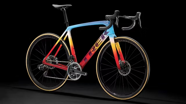
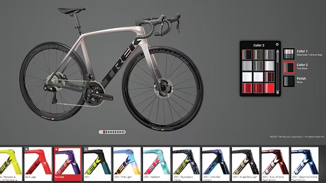
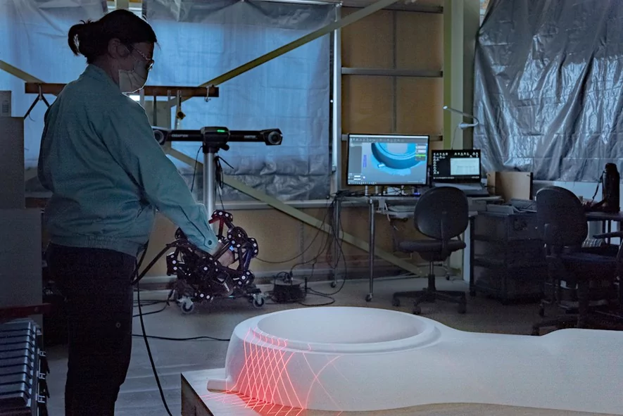
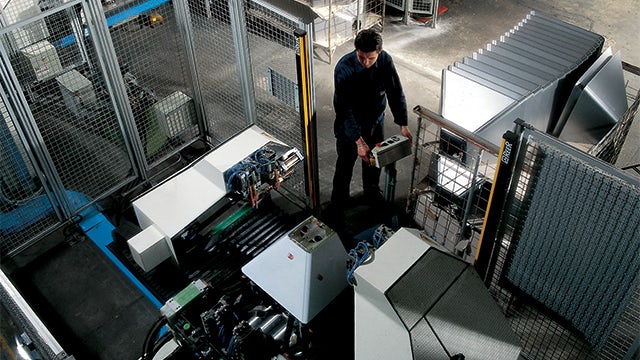
Trek’s Project One is a program that gives customers control over designing the road, mountain or electric bike of their dreams. If a customer can imagine it, Trek can make it a reality in its Project One paint shop. Project One customers have the option to choose from a pre-set combination of custom colors, paint schemes and components, or dream up a wild idea for a unique bike.

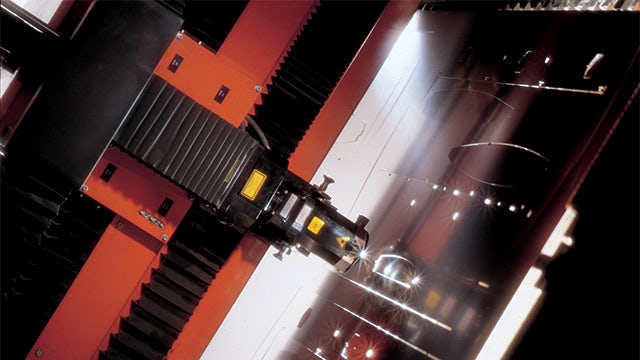
The manufacturing, painting and building of Project One bikes is performed at the Waterloo headquarters and the facility in Hartmannsdorf, Germany. Trek also manufactures the high-end carbon wheels for the custom bikes in Waterloo.

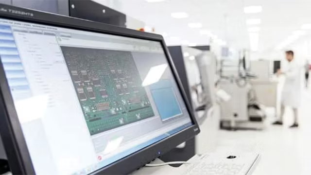
Trek has made the custom bike process streamlined, fast and easy for customers, taking every action they can to minimize lead times. That has been a challenge when there are parts shortages, but Opcenter™ software, which is part of the Siemens Xcelerator business platform of software, hardware and services, has enabled Trek to see the full picture, prioritize components for customer bikes and allocate parts to build in the most efficient way possible.

“Thanks to Opcenter Advanced Planning & Scheduling, we are able see in advance that we are going to have the parts available to build twice as much as was previously possible,” says Eric Schultz, master scheduling manager at Trek.

Digital transformation supports build-to-order

The Trek Project One program is a high-mix, low-volume, build-to-order business. Its increasing reliance on digital tools provides the best experience for its customers and partners. When a customer places an order, a production date is generated based on the availability of parts and capacity at the time of the order. Trek forecasts the components they need to buy based on what they think the customer preferences will be, rather than purchasing components for a fixed amount of production by model.

Trek’s digital transformation enables the customer to design their dream bike on a screen, place their order through their local bike shop, get an estimate on a lead time, obtain email/photo notifications during the paint and build process, and ultimately realize their concept in physical form.

“Previously, we used SQL reports and standard features in our ERP system that worked just fine on a smaller scale, but on a larger scale it just wasn’t tenable,” says Mike Lodl, director of global manufacturing. “We knew with continued business growth the current process wouldn’t be sustainable without adding more and more schedulers.”

The limitations of the existing way of working meant Trek could not test any new scenarios, do any longer term capacity analysis as supply chain issues arose, and move work order dates and sales order dates, which was a time-consuming manual process that limited growth.

Optimizing lead times

For Project One, using Opcenter enables Trek to get real-time information, marry it with part and capacity availability and deliver a top-notch bike to their customers and dealers in the shortest possible time while being as transparent and helpful as possible along the way.

“The dynamic calendar in Opcenter really helps us optimize our lead times for our customers based on how we are working and operating in each of our departments,” says Schultz.

Prior to the pandemic, Trek faced normal supply chain and inventory issues such as delays, nonconforming materials, natural disasters impacting delivery or a variety of other logistics issues. When a key component was delayed, Trek had to manually move hundreds or thousands of work order and sale order dates, then they had to find work to fill the schedule back up to keep the plant running.

“This was an incredibly time-consuming and manual process,” says Schultz. “Being a necessary, but nonvalue-added process, we knew we should try to automate or speed the process up with some type of software solution.

“There wasn’t an efficient way to expedite work or plan production if our supply chain and logistics team were able to get components in earlier.

“There were days I was spending hours manually entering dates, but now thanks to Opcenter I can use my time to do analysis or find other ways to optimize our business. Opcenter frees up hours of my time for higher added-value tasks.”

Seeking sustainability

One option was a mass data upload process, but that wouldn’t provide the analysis or intelligence Trek needed. The company reviewed several software solutions, but in the final analysis determined Opcenter was the right choice.

“Ultimately, we knew that Opcenter Advanced Planning and Schedule software was going to be the solution,” says Schultz.

“When we stated what the scope of the work was going to be, or what we wanted the software to do for us, Siemens preferred partner SNic was the only company out of three that told us, ’Yes, we’ve done that with Opcenter for other customers.’ We even spoke with other users who confirmed that they were using Opcenter in the same way we wanted to for our business.

“The combination of the software and the SNic’s expertise was unique. The team understood our challenges and were partners in developing the custom logic solution specific to our business, and Opcenter stood out for its out-of-the-box options and functionality. We also liked the fact that Opcenter had been used more widely in the industry than the other products we evaluated.”

The Opcenter advantage

According to Schultz, “Opcenter automated a lot of work. Our scheduling team would spend hours updating thousands and thousands of work order and sales order dates each time we discovered a supply issue that we couldn’t resolve. Opcenter freed up the scheduling team to do more analysis instead of spending time changing thousands of dates.

“Opcenter can help us understand what we will have components for to build in each department over time. This helps us understand where we may need to train or hire employees.

“We can manage more than twice the amount of work we used to with the same size team and we’ve avoided countless production shutdowns to ensure employees remained gainfully employed in production.”

Lodl states, “For Trek customers to be able to have the experience of getting their dream bike months ahead of time has made their buying experience outstanding.”

Egicon uses Valor and Opcenter to reduce repair rates by 80 percent while eliminating scrap

Product: Opcenter
Industry: Electronics Manufacturing

Now I can get instantaneous updates on all our manufacturing processes, without leaving my desk. I know that the systems are checking that everything is okay, instead of me – so I can spend my time on innovation and improvements.

  • Michele Magri, Production Manager
    Egicon

High-quality electronics manufacturing

Egicon is an emerging, state-of-the-art European electronics design and production house. Based in the Modena region of Italy, the company provides high-quality manufacturing services for industrial sectors including automotive, agriculture, biomedical and aerospace.

Founded in 2009, the company’s production wing was established to produce electronic control units (ECUs) for motorcycles, racing cars and luxury automobiles, in accordance with IATF 16949 quality standards. Over time the company began to manufacture additional products including medical devices, in compliance with ISO 13485 quality requirements.

In 2015, the need to provide customers with warranty support and traceability data started the company on a digitalization journey that eventually led to full automation of its manufacturing processes.

“Our search for the most suitable manufacturing execution system led us to Mentor Graphics and Cadlog, its Italian representative,” says Michele Magri, production manager at Egicon. “Valor’s point solutions and traceability solutions were a perfect fit.”

The digitalization journey

“The automation process began with a simple data collection system and accelerated from there,” says Magri. “We invested heavily in ECAD and MCAD systems and deployed the Valor® Process Preparation software in order to achieve a single, unified flow of information between our design and production departments. This was especially beneficial in NPI execution.”

“Initially, the Valor point solutions package was used to connect our machines, warehouse and assembly and testing processes to our central database, in order to achieve traceability of materials,” Magri explains. “Soon after, we realized that the solution was completely suitable for the monitoring of productivity and overall equipment effectiveness. By 2017, all Egicon processes were connected to the Valor system, replacing all manual data collection systems and tracking KPIs in real time. In 2019, we installed the Opcenter Execution Electronics IoT software to improve data collection and gain the benefits of the greater flow of data, which allowed us to benefit from the Opcenter Intelligence Electronics analytics software. We’ve turned the paperless factory into a reality.”

How it works today
With a staff of 60 and yearly revenues of €10 million, Egicon is considered one of the most interesting emerging companies in the field of technology development and production.
Opcenter™ Execution Electronics IoT software is fully integrated into Egicon’s production and quality systems, allowing continuous monitoring via the overall equipment effectiveness (OEE) dashboard, enabling managers to see the state of work-in-progress, in real time. The quality department is instantly notified regarding quality events, leading to a significant reduction in waste-related costs.

The Valor and Opcenter solutions at the core of Egicon’s production systems are part of Siemens Xcelerator business platform of software, hardware and services. Egicon releases at least 200 new product introductions (NPIs) or updates for review each year, and the Valor Process Preparation suite manages all product changes and releases.
Valor Material Verification verifies that all materials and tools are set up before assembly, improving efficiency and quality. The software also provides maximal flexibility by supporting functions such as alternate parts, an approved vendor list (AVL), free feeder positioning, dynamic alternate positions, blocked material and safe splicing.

Opcenter Execution Electronics IoT and Opcenter Intelligence Electronics provide comprehensive, Industry 4.0-ready shop floor data collection and analytics, which connect to all the processes and machines for data collection and full traceability. Customers are assured of the highest levels of traceability (IPC1782 levels three and four) at no additional cost. Egicon, which previously had a one-month lead time for quality and production reporting, now offers these services in real time. “Now I can get instantaneous updates on all our manufacturing processes, without leaving my desk.” says Magri. “I know that the systems are checking that everything is okay, instead of me – so I can spend my time on innovation and improvements.”

“Using the tools provided by Mentor Graphics and Cadlog, we are able to reduce our repair rate from 30 ppm to six, and achieved a scrap rate of zero percent in 2019,” Magri explains. “Our customers appreciate the improved levels of service, and thanks to these innovative solutions, we can often anticipate their quality system requests. This has increased our customers’ level of confidence in us and helps us to attract new business. We are using Valor point solutions to avoid manual registration of quality events, and we are using the Valor foundation for monitoring the work in progress. Elimination of scrap product is related to real-time monitoring of quality events and is a result of continuous improvements ensured by the manufacturing analytics platform.”
Future plans
Moving forward in the Industry 4.0 vision, Egicon plans to leverage the ISA95 data connectivity layers to drive excellence using applications such as analytics and machine-to-machine (M2M) and other micro-solutions.
Using the tools provided by Mentor and Cadlog, we were able to reduce our repair rate from 30 ppm to six, and achieved a scrap rate of zero percent in 2019.
Michele Magri, Production Manager
Egicon

AUTOCUT OPTIMIZES CUTTING FILM PATTERN DIGITALIZATION THANKS TO METRASCAN 3D

Product: MetraScan 3D
Industry: Automotive

Based in South Korea, Autocut is an automotive paint protection film (PPF) and tinted film solutions provider. It delivers software with 17000+ pattern data of paint protection films (PPF) and pre-cutting films for automotive aftermarket shops. Pre-cutting of the film based on the shapes of car parts is needed for productive PPF projects. With over 15 years of expertise, Autocut’s solutions are adopted in over 100 shops in South Korea.

Traditionally, Autocut’s development team performed measurements manually, using tape and transparent paper, in order to design new patterns. Film cutting was also carried out by hand. Unfortunately, these processes did not provide consistent results as the patterns tended to vary based on shop floor conditions. Large patterns, which couldn’t be covered by paper and film, were difficult, if not impossible, to make.

Autocut’s digital transformation: The search for the right 3D scanner

Sangwon Jung, Autocut’s CEO, and Chango Kim, Director, decided to look for a more modern alternative and transition towards digitalization. “We wanted both hardware and software that were easy to use and reliable,” explained Jung.

The team looked into several 3D scanning technology vendors; unfortunately, after extensive testing, the quality of the scans was poor, and the software platforms were not very intuitive. Some of the scanners could not even show a clear image because of severe reflections or distortion of colours on the boundary lines.

Creaform’s 3D scanners take on Autocut’s most challenging projects

Autocut then took Creaform’s metrology-grade 3D scanners for a test drive. “Creaform’s solutions were different,” Jung said. “They are very user-friendly, and the software is equally easy. We knew right away that we could deploy these solutions very quickly into our existing workflows.”

The company acquired Creaform’s MetraSCAN 3D and Go!SCAN 3D scanners, along with VXelements software, an advanced 3D metrology software platform. The results were almost immediate. Technicians can quickly scan a vehicle and get the 3D measurements they need in a very short timeframe. Jung and Kim estimate that the 3D scanners have improved efficiency twofold.

Creaform’s 3D scanners also drastically reduced repetitive tasks. “Once the components are scanned the first time, it is simple to expand and modify them with additional new patterns—all while ensuring consistency,” Kim added. This means that technicians can derive as many patterns as they want by analyzing and substituting various 3D models. Autocut also observed major efficiency gains when it came to highly customized film cutting for specific cars, which inevitably allowed the company to take on even more projects.

Contrary to other 3D scanners on the market, MetraSCAN 3D and  Go!SCAN 3D generated clean and accurate data in real time without any limitations, including white, black, shiny and reflective surfaces. Complex geometries could also be captured with ease. In addition, VXelement’s post-processing capabilities accelerated development thanks to the software’s versatile features and fast treatment.

We were very happy with the immediate technical support and continuous software updates,” Jung said. The team was able to rely on Creaform’s responsive local experts for any questions or troubleshooting—a must for businesses that are just starting out with 3D scanning technologies.

Autocut plans to expand into other sectors in the short term by offering services for motorcycles, bicycles and golf clubs. “We believe that thanks to Creaform’s 3D scanners, our business has greatly improved customer satisfaction and helped us to gain a competitive edge in our market.”

Sakai increases the efficiency of its dimensional inspections with a new approach

Product: Metra 3d
Industry: Industrial Machinery and Heavy Equipment

Many companies are now accelerating their efforts to reform the way they work, and in Japan, where there is a shortage of engineers, the manufacturing is the industry that has the most pressing need to address this issue. In addition, with the retirement of the baby boomer generation of veteran engineers, many companies are facing the challenge of passing on skills to younger workers, and an increasing number of companies are working to improve the efficiency of measurement work at production sites, which had been inefficient.

In the past, manual measurement using callipers was the common method, and it took an enormous amount of time to measure styrene foam curved and free-form shapes. In addition, measurement work often tends to rely on the tacit knowledge of veteran employees, and it can take several man-hours to compare the measurement results with the original CAD data. Also, in order to ensure measurement accuracy, the production line must be temporarily stopped, which in some cases leads to inefficient operations.

Sakai Model Making Corporation is a manufacturer that makes the most of its technology and experience, accumulated over more than half a century, to produce a variety of models, including casting models for flans, V-process, automatic molding machines, molds, resin mold, and full-mold. The company’s business model is to take orders directly from machine tool manufacturers and work in association with casting manufacturers, flexibly changing the shape, size, and number of models delivered on a case-by-case basis in response to customer requests. Sakai Model Making was facing the same measurement problem.

In addition to these measurement issues, Sakai Model Making Corp. also faced the challenges of dealing with a declining workforce due to the falling birthrate and aging population, passing on skills, training young workers, and work styles evolution. We interviewed the core members of the project about the 3D measurement efforts undertaken by Sakai Model Making Corp.

Urgent need to improve dimensional inspections, which are too generic and inefficient.

Before shipping a model, quality assurance through dimensional inspection is essential. The measurement was conventionally done by hand, which is a highly difficult task because many of the models are castings, contain many curved surfaces, and have complex shapes. In addition, since most models are made of styrene foam, which is soft and brittle, great care must be taken when measuring them. Dimension evaluation was performed by carefully applying a ruler or a convex gauge to each spot, and in the case of complex curved surfaces, a special gauge may have been specially made for measurement.

The size of castings varies from palm-sized to as large as 10 meters. Naturally, since the model is the part that carries the foundation, the delivery of a high-quality and high-precision model is required.

The dimensional accuracy required for model making is between 0.5 mm and 1 mm, but it is not realistic to manually measure each detailed dimension of a model. Therefore, it was necessary to determine which dimensions were important when releasing the molds or finishing the castings and to correctly evaluate the measurement points. In addition, only I could make the final evaluation during the pre-shipment inspection. Therefore, I sometimes spent almost the entire week before shipment doing nothing but inspections. I had no choice but to stop quotations and other work while inspections were being conducted.

Sakai Model Making Corp. Representative Director Mr. Naruhito Sakai

The pre-shipment dimensional evaluation at Sakai Model Making Corp. was a manual process, a technique that Mr. Sakai had acquired through trial and error and by feel over many years. “Because of this reliance on tacit knowledge, it was difficult to formalize and pass on to other staff within the company”, he says.

“Had we continued with the same system as before, it would have been difficult to maintain our customers’ trust for the future. To break out of this situation and improve our operations, we decided to move to a digital approach,” said Mr. Sakai.

MetraSCAN 3D was chosen for its overwhelmingly fast measurement speed and compactness

As a means of improving the measurement process, Sakai Model Making Corp. turned its attention to 3D scanners, which can scan actual curved surfaces and complex shapes simultaneously with a laser and digitize them as 3D data. Mr. Isonuma took the lead and began comparing products.

The biggest drawback common to all the 3D scanners we were considering at the time was the measurement speed,” said Isonuma. One product took eight hours just to measure, and we thought this was not practical.

Sakai Model Making Corp. Technical Engineer Mr. Yasuhumi Isonuma

The slow measurement speed was a deal breaker to Sakai Model Making Corp.’s models, many of which were also large and included a considerable number of measurement points. In addition, the factory was cramped with processing equipment, and a large measuring machine would have overwhelmed the limited workspace.

To enable anyone, regardless of experience, to perform 3D measurements, compactness is a must. Also, measurement speed is important to respond quickly to customer requests. When we were looking for a 3D scanner that met these requirements, we learned that a casting manufacturer we do business with was using a handheld MetraSCAN 3D with exactly these features, so we immediately contacted the manufacturer. When we tried the MetraSCAN 3D, we found that the scanning speed was very fast and the 3D data could be visualized in real time on the PC screen while the measurement was in progress. We ended up selecting this scanner as it was the only solution meeting all the requirements.

The ability of the MetraSCAN 3D to scan large objects at high speed and to perform accurate 3D measurements of complex shapes in a short time was a decisive factor in our decision to introduce the system.
The scan results are visualized in real time on the PC screen using the included VXelements software, allowing the user to check on the spot whether the scan was done well enough to create 3D digital data of the product quickly and efficiently, while avoiding unnecessary rework.

Another advantage of the MetraSCAN 3D is that it can measure both large and small objects, and large objects can be scanned without the need to recombine and realign data later. Furthermore, since there is no need to attach targets, measurements can be performed one after another, even if there are dozens of objects to be measured. This is a unique feature of the C-Track, which was developed for automated self-positioning systems that can perform 3D measurement of large objects with high accuracy and speed.

Standardization and simplification of measurement work dramatically improve work efficiency

After implementing MetraSCAN 3D, the system administrator at Sakai Model Making Corp. saw immediate results in the measurement operations.

Anyone can learn calibration and measurement using the MetraSCAN 3D with just a simple explanation of its operation. Of course, it takes some time to be able to edit data and create data for inspection, but the measurement work itself was learned by new employees on their first day on site.

MetraSCAN 3D is a high-performance CMM, yet it is easy to operate. New employees who have been with the company for only a few months quickly learn to operate it, and they are now measuring products as part of their daily work.

Mr. Sakai continued, “When I used to measure the dimensions of medium-sized models manually, the measurement work alone used to take a day and a half, but MetraSCAN 3D has reduced the time to half a day. I still make the final evaluation myself, but now that I am free from measuring and reporting, I no longer have to spend a week just for pre-shipment inspections. The time saved can now be effectively utilized for making quotations,” he says.

Currently, Mr. Isonuma uses 3D data to create processing data, which is then checked by the system administrator before being converted into machining data. The assembled products are then measured with the MetraSCAN 3D, and the design data and the 3D data obtained from the measurement are superimposed and compared. In addition, since the measurement results are stored as 3D data, a quality assurance system for customers after delivery has also been established. It is not just a matter of improving inspection efficiency; the business process itself is being digitized.

Data measured by the MetraSCAN 3D is compared with CAD data in VXinspect, the included software, and after the measurement work is easily performed, the data is stored as product shipment inspection data by Sakai Model Making Corp.

Accelerating business efficiency with 3D data to begin a new era

Sakai Model Making Corp. plans to further automate its work system, including pre-shipment inspections, to create an environment in which operations can be carried out mainly by younger workers without relying on skilled workers. The company also plans to utilize MetraSCAN 3D and 3D data not only in the inspection process, but also in the manufacturing process. As part of this plan, the company plans to use 3D printers as well, aiming to further improve operational efficiency.

“The recent Corona problem and geopolitical issues have made the procurement of wood and other materials unstable, and prices have skyrocketed. In addition, the company will lose credibility if it does not address the SDGs. To address these social issues, we will work to further improve efficiency using 3D data,” said Mr. Sakai, expressing his plans for the future.

Automotive testing firm uses Simcenter Testlab and Simcenter SCADAS to help customers meet regulatory standard for noise

Product: Simcenter
Industry: Automotive and Transportation

Working in partnership with Siemens, UTAC CERAM is looking to the future of automotive acoustic design, including virtual homologation, predictive pass-by noise design and sound optimization of AVAS-fitted vehicles.

Louis-Ferdinand Pardo, Acoustic Expert Leader and Department Manager, Electromagnetic Compatibility and Noise, Vibration and Harshness
UTAC CERAM

Passing the first time

Scientists are confident that noise pollution can harm the health and behavior of all beings, so reducing the noise levels generated by cars, airplanes and machines is a requirement for supporting a sustainable future.

Governments worldwide, especially in Europe, are taking drastic measures to enforce more stringent vehicle pass-by noise (PBN) levels. In June 2016, Europe issued a plan for diminishing regular passenger car noise levels from the current level of 72 decibels (dB) to a maximum of 70 dB by 2020 and 68 dB by 2024. Achieving a 4-dB reduction will take an enormous effort, as vehicle manufacturers are already pushing engineering limits to remain below the current target.

Vehicle manufacturers and part suppliers will simply have to work hand-in-hand to deliver systems that meet individual and overall acoustic targets. Special attention will have to be given to the components generating the most noise: the powertrain, intake, exhaust and tires.

Every vehicle needs to be certified by the International Organization for Standardization (ISO) 362 standard, which has been revised in recent years. It now requires more extensive tests in order to even better represent the reality of urban traffic. Testing teams are already spending lots of effort on performing the regular homologation tests and have little to no time or resources to spare.

The reality is clear: Vehicles need to be designed to be able to pass the test the first time.

Getting ready for the future

For decades, UTAC CERAM has helped vehicle manufacturers pass certification and homologation tests. UTAC CERAM is a private, independent group providing services in many areas of land transportation: regulation and approval, testing and technical expertise (environment, safety, durability and reliability), certification, public automotive events and driver safety training. UTAC CERAM also works in an official capacity with two French regulatory institutions that oversee standards for roadworthiness (Central Technical Organization) and standardization (Office for Automotive Standardization).

Over 400 employees work at two test centers in Linas-Montlhéry and Mortefontaine, France, as well as at customer sites in France and abroad. In addition, UTAC has subsidiaries in the United Kingdom, North America, Russia and China.

Vehicle pass-by noise homologation is one of many UTAC CERAM activities. Numerous vehicles are tested each year according to the ISO 362 standard on the exterior pass-by noise track at the Linas-Montlhéry site. Yet UTAC CERAM’s involvement in the automotive industry goes beyond simple homologation. The company offers solutions for automotive design and testing so manufacturers can be confident their vehicles will pass the ultimate homologation test.

For the purpose of mastered pass-by noise design, UTAC CERAM has invested in a state-of-art acoustic chamber. The large facility features fine-tuned sound insulation, a four-wheel drive roller bench and two rows of microphones combined with Siemens Digital Industries Software’s Simcenter Testlab™ software for analysis and Simcenter SCADAS™ hardware for acquisition. As such, it is designed to reproduce the conditions of exterior pass-by noise tests as accurately as possible.

The benefits of indoor pass-by noise testing are huge. Indoor pass-by noise testing lets teams perform accurate, perfectly reproducible tests in a controlled environment, independent of changing weather conditions. Since vehicle speed and gear shift are robotized, risk of human driver error is eliminated. However, tire noise is more difficult to accurately reproduce in a room, as it sounds different on a roller bench than it does on road surfaces. This is why Simcenter Testlab Pass-by Noise Testing software, part of the Simcenter™ portfolio from Siemens, features a tire noise model calculation that corrects tire noise data according to the ISO 362-3:2016 procedure.

Thanks to the repeatability of tests, results are more reliable. In the intermediate term, it is expected that indoor pass-by noise tests will be performed for vehicle homologation and will complement or replace exterior tests. Louis-Ferdinand Pardo, acoustic expert leader and department manager of electromagnetic compatibility (EMC) and noise, vibration and harshness (NVH) at UTAC CERAM, confirms this trend based on his experience as a member of the ISO committee defining the standard for pass-by noise level.

But the benefits of indoor testing go beyond eliminating the occurrence of chance, errors or incidents in a test. Testing in a controlled environment allows the user to implement advanced pass-by noise engineering techniques. The noise contributions of individual sound sources, such as powertrains, exhausts and intakes, can be evaluated and calculated to help set precise acoustic targets for the components.Getting ready for the future

Shaping the sound of electrical vehicles

Vehicle sound design is not about the reduction of noise levels alone. Today, an increasing number of hybrid and electrical vehicles are being used in urban areas. These vehicles drive fairly softly. The risk of accidents rises when no sound alerts pedestrians or cyclists of the presence, speed and direction of an approaching car. To preempt this risk, governments and institutions have been debating the necessity of equipping hybrid and electrical vehicle with noise-generating warning devices described as acoustic vehicle alerting systems (AVAS).

In 2016, the United Nations (UN) published a new regulation (UN 138) on minimal noise requirements that would enforce the fitting of such systems on new vehicles within a couple of years. In the same year, the United State National Highway Traffic Safety Administration (NHTSA) drafted a final rule establishing the federal motor vehicle safety standard (FMVSS 141) of minimum sound requirements for hybrid and electric vehicles.

Testing of AVAS-fitted cars will be best performed indoor as noise levels are by definition low and background noise should be excluded. Simcenter Testlab Interior Pass-by Noise Testing supports the definition of minimum noise levels by integrating the ISO 16254 standard (Acoustics – Measurement of sound emitted by road vehicles of category M and N at standstill and low speed operation – Engineering method) in its worksheets. With its state-of-the-art acoustic facility equipped with Simcenter testing solutions, UTAC CERAM is well positioned to support manufacturers of hybrid and electrical vehicles design sound for the alerting system.Shaping the sound of electrical vehicles

Optimal testing productivity

To perform an indoor pass-by noise test, the vehicle is positioned and secured on the four rolls of the roller bench. The vehicle stands in the middle of the large chamber with two rows of about 20 microphones, each positioned on the sides of the chamber at an exact distance of 7.5 meters from the vehicle and a height of 1.2 meters. The microphones send their signals to the two Simcenter SCADAS hardware mobile data acquisition systems, part of the Simcenter portfolio, at each side of the room. Once the vehicle is positioned on the roller bench, the engineer starts the test. From that moment on, most of the procedure is automated. The engineer leaves the acoustic room for the control room, where he or she will be able to set up the parameters for the test and run it remotely. If necessary, the test can also be adjusted and started manually from a control box in the room.

At UTAC CERAM, the installation has been designed to ensure maximal testing productivity.

“We have selected the Simcenter testing solutions from Siemens for three main reasons,” says Pardo. “First, it offers excellent data quality and processing capabilities for indoor pass-by noise with algorithms that deliver accurate results, comparable to the ones obtained with actual exterior pass-by noise tests. Second, using Simcenter testing solutions ensures continuity and compatibility of tests performed indoor with tests executed outdoor with similar Simcenter systems. Third, we really appreciate the long-standing partnership with Siemens for acoustic engineering and testing.

“Siemens’ involvement in pass-by noise engineering is not limited to supplying measurement equipment; the company acts as a partner in research and development, providing solutions for acoustic source quantification and evolving towards early, predictive vehicle pass-by noise design. Siemens is also involved, as am I, in the definition of tomorrow’s ISO certification procedures, moving towards virtual homologation.”

Performing state-of-the art tests and beyond

New ISO certification procedures prescribe more exterior tests at run-up and constant speeds, and in various gear ratios. Those requirements can be reproduced in UTAC CERAM’s acoustic chamber, which allows the user to assess a design variant as well as prepare for vehicle homologation. Test procedures are preprogrammed in the chamber’s controller: the engineer only adjusts the parameters according to the requirements of the vehicle under scrutiny, opens the Simcenter Testlab worksheet and initiates the test. It then runs autonomously, with triggers starting and stopping measurements in Simcenter Testlab. Yoni Meyer, test engineer at UTAC CERAM, is an enthusiastic user of the software: “We benefit from almost all the implemented functionalities of Simcenter Testlab, and despite being advanced users, we still appreciate the easy-to-use worksheets and intuitive workflow approach.”

By using the postprocessing capabilities of Simcenter Testlab, further tasks, such as separation and quantification of noise sources, can be performed. The result is being able to clearly identify the noise contribution of individual components. This analysis will allow exact acoustic target setting on components, and means in the future the user will be able to accurately predict vehicle pass-by noise level based on component noise contribution.

Pardo concludes: “Working in partnership with Siemens, UTAC CERAM is looking to the future of automotive acoustic design, including virtual homologation, predictive pass-by noise design and sound optimization of AVAS-fitted vehicles.

We benefit from almost all the implemented functionalities of Simcenter Testlab, and despite being advanced users, we still appreciate the easy-to-use worksheets and intuitive workflow approach.

Louis-Ferdinand Pardo, Acoustic Expert Leader and Department Manager, Electromagnetic Compatibility and Noise, Vibration and Harshness
UTAC CERAM

Microsoft Flight Simulator, one of the most beautiful games in the world, uses Artec Leo to recreate ultra-realistic aircraft

Product: Artec LEO
Industry: Aerospace and Defense

Microsoft Flight Simulator

Cockpit view in the game Flight Simulator

Fourteen years following the last release of the world-famous flight simulation game, on Aug, 18, 2020, Microsoft and Asobo Studio unveiled the newest edition of Flight Simulator.

Already number one on the best-selling PC games chart since its release, Microsoft Flight Simulator is a worldwide hit, boasting more than 1 million unique players, with 26 million flights already having been flown in this super realistic simulation.

To recreate the game environment, the graphics, and the plane cockpits to the peak of perfection, Asobo Studio needed to faithfully include every last detail. This is even more important since the majority of players are pilots, passionate airplane enthusiasts, and other expert gamers with extensive knowledge of flight simulators.

3D technologies to help with performance imperatives

Engineers from Asobo Studio, France’s leading independent game developer for PC and consoles based in Bordeaux, used 3D scanning technologies to recreate with true-to-life precision the planes’ cockpits in the game, making even the tiniest details more realistic in this new release of Microsoft Flight Simulator.Microsoft Flight Simulator

Asobo vehicle designer scanning the inside of an aircraft with Artec Leo

This is why teams from Asobo Studio had to visit various runways to digitize multiple planes, ranging from aerobatic two-seaters all the way up to jumbo jets, with every aircraft scanned meticulously.

Those scanning operations took only a few weeks, and were accomplished with the help of the handheld 3D scanner Artec Leo, a device capable of scanning 80 frames per second, and operated via a simple touchscreen. The scanner was provided by 3D Numérisation, an Artec 3D partner.

This way, Artec Leo was used to rapidly capture the colors, shapes, and precise dimensions of a Robin DR 400 aircraft, as well as many other planes.

Once the planes are scanned, the data is then processed in Artec Studio software, where the scan mesh densities are reduced and optimized to match the game engine requirements before the scans are exported for further development. Artec Studio allows the user to create, edit, and process all the 3D data at hand, whatever the size, or resolution of the object being captured. Each scanned aircraft needs around one working day of software processing in order to be ready for export.

Ease of use, ultra-realism, and time saving

Artec Leo, which is capable of scanning any type of object, was also used to digitize other parts of the aircraft, such as the landing gear and fuselage.

It is obviously much faster to scan an existing object than to recreate it from scratch using 3D modeling software. 3D scanning technologies allow users to digitally bring to life an object identical to its real-world counterpart. To show how fast the process is, scanning a plane took from half a day to one day, depending on its size. Entire cockpits and landing gear could be captured in merely an hour.Microsoft Flight Simulator

Ultra-realistic aircraft models are tested inside the simulator

“We could capture a huge amount of data in such a short time, while changing the angle of scanning very quickly,” said Nicolas Favre, Vehicle Artist at Asobo Studio. “During the digitization process, the only difficulty was to find enough distance to scan the instrument panel inside the cockpit, which is a narrow cabin. Without 3D scanning, it would have been way longer and more difficult to reproduce such a high level of precision, especially for the many knobs and buttons inside the cockpit.”

“3D scanning was crucial in regards to time savings, and let us skip some quality control checks from different aircraft manufacturers who had to give us their authorization to validate our work. With 3D scan technologies, we could go directly to the modelization phase while earning trust and credibility from the manufacturers, who could verify the accuracy of our aircraft and cockpit models in our game,” explained Gabriel Turot, Vehicle Artist at Asobo Studio.

Asobo Studio, always up-to-date with the latest technologies, considers this 3D scanning project as a “Laboratory for ideas” to eventually use on other future projects, with the objective to create even more realistic video games.

Andrey Vakulenko, Chief Business Development Officer of Artec 3D, concluded “With this approach to simulation game development, anyone can virtually step inside an aircraft cockpit that’s vividly identical to the original. It is simply stunning to experience the results delivered by Asobo Studio for creating the planes in Flight Simulator. The Artec Leo scanner is normally used for the design of actual aircraft, and ensuring quality control of their parts. It is exciting to know that now everyone can enjoy 3D models of these planes with a level of quality chiefly used by aeronautical engineers. This opens the gates for countless developers across the video game industry, but also in virtual reality and augmented reality as well.”

Faber, a leading brand of kitchen hoods, integrated its entire product development cycle, from CAD to ERP, using Teamcenter

Product: Figure 4
Industry: Consumer Products and Retail

Siemens Digital Industries Software representatives have always been proactive and practical; they became quickly familiar with the technical jargon of our organization and responded knowledgeably to the questions of our designers, who use Pro/Engineer. Integration between two different vendors obviously caused some doubts, but Siemens PLM Software’s experience in this kind of integration offered solid assurancesthat have turned out to be true.

Elisa Galassi, IS Manager
Faber SpA

Imagining, designing and manufacturing kitchen hoods

For fifty years, Faber SpA (Faber) has been imagining, designing and manufacturing hoods, becoming a leader in the global scene, not only in Italy, where one out of two hoods is made by Faber. Established in 1955, the company has been expanding constantly through acquisitions all over the world until 2005, when all of the organizations were acquired by Switzerland’s Franke Group, leaders in sinks. Today, the Faber brand is managed within Franke Group’s Hoods Product Line. As the “air specialist” within the group’s Kitchen Systems division, Faber is in charge of coordinating the activities of group companies across India, Turkey, Argentina, Sweden, France and Russia.

Fabriano, the historical headquarters of the company in the Marche region, is home to the major research and development (R&D) center of the group; other R&D centers are located in Sweden and in Pune, India, where a manufacturing plant is planned.Imagining, designing and manufacturing kitchen hoods

PLM starts in Fabriano

To handle the coordination of product development activities assigned by Franke Group to Faber after the acquisition, the Fabriano site managers immediately started looking for a suitable tool to improve coordination and synergy among all group companies. Samuel Riitano, R&D manager of the Hoods Product Line at Faber, explains: “For our product development and product lifecycle management (PLM) operations, we initially tried to centralize data searches using replicated databases; however, this approach was inadequate, mainly because we wanted to maximize re-use on one side, and to create an orderly R&D process on the other. When your organization is articulated and distributed, you need clear rules to manage projects within distributed teams having different cultures and languages. We were looking for a solution to keep everything together, defining accurate and clear working methods and procedures for all stakeholders.”

In early 2008, the company launched a scouting activity aimed at the analysis of platforms that might respond to Faber’s requirements. “Besides Windchill and SAP, which we were already using, we extended our evaluation to a third option, Teamcenter from Siemens Digital Industries Software,” says Marco Castellani, who is responsible for BI and SOA (business intelligence and service-oriented architecture) at Faber. “For all software candidates, we checked integration with our CAD (computer-aided design) package Pro/Engineer and held a number of meetings with our research and development group to consider possible developments in PLM. From the very start, a preference emerged for Teamcenter.”

After three years of analyzing the potential value and benefits of adopting a PLM solution that, starting from the hoods product line, could then be deployed across the entire organization, management re-activated the technology search in 2011. “At the end of this further analysis, everyone agreed that the PLM solution by Siemens Digital Industries Software was the right platform,” Castellani adds. “A pilot project was launched in Fabriano to prove the benefits offered by the introduction of PLM.”PLM starts in Fabriano

Quickly up and running

Only a few months after implementation, Teamcenter® software was in full productive use in Italy and Sweden, while other group companies in Argentina, India and Turkey primarily employed it for visualization. Everyone had direct, real-time access to all design information available in the database. “We have more than 30 people using Teamcenter,” says Elisa Galassi, IS (information systems) manager at Faber. “Besides utilizing vaulting functionality with drawing check-in and check-out, project data management, workflows and drawing approval cycles, we have completed the integration with SAP, the ERP (enterprise resource planning) software adopted by Franke Group across the entire organization, enabling data exchange with the database for component searches based on item codes transferred between Teamcenter and SAP.”

The Teamcenter implementation at Faber is significant for the Italian market, where PLM culture often boils down to CAD file vaulting and management. “We are completing the component classification process, for which we have created and populated most of the tree,” notes Galassi. “We are now defining the proper management of engineering change orders (ECOs) and finalizing the model for engineering bill of materials (EBOM) management with the introduction of configuration.” He adds, “It is very easy to work on the EBOM using Teamcenter.”

Riitano adds, “This will be the final step of the first phase; afterwards, we will move out of engineering to define requirements for sales and manufacturing operations. Potentially interesting developments include cost quantification and new product costing. We are considering the direct involvement of our supply chain, via a portal that collects information from Teamcenter and makes drawings, specifications and other information available to our suppliers. Each supplier will then have access to all necessary information to prepare a quotation and post it on the portal, with a fully traceable process. As for costing, we would like our designers to read the cost of existing modules directly from the ERP system to estimate the cost of a new product; then, purchasing and business administration will be in charge only for new components.”

Galassi notes, “We know that, using Teamcenter, you can open a view into SAP, to retrieve any information when you need it, without frequent updates and synchronization between the two systems.”Quickly up and running

Tangible benefits

Faber management essentially identified three benefits resulting from the first phase of the implementation. First, full integration with the corporate ERP software enables quicker and leaner information searches for all engineering department users, who can work through one single interface and one desktop. Second, the management of drawings and technical information is more accurate and reliable, and, after initial database population, much faster. Third, structured workflows guide users through subsequent project stages without using paper documents or email messages, thus improving the tracking of all activities.

Benefits expected in the second stage are equally important, starting with the SAP® software integration. Castellani explains, “As soon as we complete the integration of the engineering bill of materials with ERP, we will have one single document describing the product in Teamcenter and SAP, with an optimized information transfer between designers and item code creators; this transition is critical both for the typical issues related to data transfer, and for time. With Teamcenter, we are confident we will minimize both. It is worth noticing that the integration between Teamcenter and SAP integration is bidirectional, a unique situation in Italy.”

According to Riitano, once finalized, component classification will enable a better use and increased re-use of components, particularly useful in foreign sites even more than in Fabriano, where employees have proven experience and a deep knowledge of all components. He explains, “By collecting and classifying all components in a unified system accessible on a global scale, we will help all our users avoid useless duplications or re-create parts and objects that already exist somewhere.” The benefits of classification are apparent for a company like Faber that manages 400 to 500 codes across 100 product families, plus the entire Franke Group catalog and models for its OEM customers. “The current portfolio includes active codes for approximately 5,000 finished products and almost 300 models, and every year we generate more than one thousand new finished product codes,” say Riitano. “If we refer to components, we have 40 to 50,000 codes of raw materials and semifinished products.”Tangible benefits

Promising developments

“We are pleased with the service offered by Siemens Digital Industries Software, starting from the initial approach with a high-impact presentation and proposal,” says Galassi. “Siemens Digital Industries Software representatives have always been proactive and practical; they became quickly familiar with the technical jargon of our organization and responded knowledgeably to the questions of our designers, who use Pro/Engineer. Integration between two different vendors obviously caused some doubts, but Siemens Digital Industries Software’s experience in this kind of integration offered solid assurances that have turned out to be true.”

We are pleased with the service offered by Siemens Digital Industries Software, starting from the initial approach with a high-impact presentation and proposal.

Elisa Galassi, IS Manager
Faber SpA

High Density Stacking Capability Drives Productivity in End-Use 3D Part Production at Decathlon

Product: Figure 4
Industry: Consumer Products and Retail

Decathlon, the world’s largest sporting goods retailer, is using the high-speed Figure 4 platform and new stacking feature of 3D Systems’ 3D Sprint® software to enable direct production of 3D printed end-use parts. The stacking feature enables batch production of one or multiple parts through a combination of user-defined and automated tools, and removes significant time from the print preparation process.

“By stacking parts we are able to print in batches of 100, and have reduced the time it takes to prepare a build from 30-60 minutes to just 6-10 minutes. The combination of stacking and production-grade materials makes Figure 4 ready for production.”

– Gregoire Mercusot, Materials Engineer, ADDLAB, Decathlon

Decathlon eyeglass component designed to connect the lens to the frame

Decathlon used Figure 4 to solve an injection mold problem for a small component for shooting glasses that connects the frame to the lenses.

The Challenge

VALIDATE EFFICIENT PRODUCTION WITH ADDITIVE MANUFACTURING

When faced with a mold injection problem on a small component for shooting glasses that connects the frame to the lenses, Decathlon opted to test the new 3D stacking solution developed by 3D Systems to evaluate additive manufacturing for production. After conducting a feasibility study on the Figure 4 solution and stacking feature, Decathlon’s teams confirmed the productivity and economics of additive manufacturing and decided that this solution could be considered for batch-run production of the final product.

Figure 4 build plate full of stacked 3D printed parts

Figure 4 solution with 3D Sprint stacking feature enables batch-run production.

The Solution

01 Part Stacking Feature in 3D Sprint Software

Decathlon’s additive manufacturing lab (ADDLAB) uses 3D Systems’ Figure 4 3D printing solution across a range of applications (including mold master patterns), and is now considering using the new high density part stacking capability of 3D Systems’ 3D Sprint software to facilitate direct production. 3D Sprint is an advanced, all-in-one software that streamlines the file-to-pattern workflow with tools for print file preparation and optimization, including automatic support generation, and optimized part placement to maximize productivity. The new stacking feature helps users print high volume batches with an efficient file preparation workflow.

To use the stacking feature, users import a part and base file, define the stack in terms of orientation and part quantities, and use automated tools to replicate consecutive vertical stack layers and supports. According to Decathlon engineer Gregoire Mercusot, stacking has reduced print preparation time by as much as 80%. Builds that used to take 30 minutes to an hour to prepare can now be completed in six to 10 minutes.

Mercusot says the utility of this function goes well beyond production: “I use this feature several times a week whenever I need multiple parts. It’s incredible for production, but it’s also very useful for prototyping,” he says.

Screenshot from 3D Sprint software demonstrating strut feature for stacked manufacturing

The stacking feature of 3D Sprint helps users print high volume batches with an efficient file preparation workflow.

02 Production-Grade Materials

Decathlon is using the Figure 4® PRO-BLK 10 material for this functional eyeglass component, citing the material’s strong rigid properties and fast print speeds (62 mm/hr) as key benefits. This high precision material produces parts with smooth surface finish and sidewall quality, and has excellent long-term mechanical properties and environmental stability, bringing a new level of assurance to 3D production. From its production feasibility study, Decathlon confirmed reproducibility across print batches and full functionality of the part.

End-use part produced at Decathlon using Figure 4 stacked manufacturing

The stacking capability of Figure 4 brings efficiencies of scale to post-processing as well as part building.

03 Print Speed

Figure 4 is a projection-based additive manufacturing technology that uses a non-contact membrane to combine accuracy and amazing detail fidelity with ultra-fast print speeds. Decathlon uses the Figure 4 Modular system to print stacks of 100 parts in 85 minutes, which is equivalent to just 42 seconds per part. The Figure 4 Modular is a scalable, semi-automated 3D production solution comprised of a central controller that can be paired with a single printer-module up to 24 printer modules, making it a flexible option that poises businesses for growth.

04 Post-Processing

The high-density stacking capability of Figure 4 brings efficiencies of scale to post-processing as well as part building, allowing Decathlon to treat a batch of parts the same as a single part. This means that the time it would take for Decathlon to clean, cure, and remove the supports from a single part remains the same, even for a batch of 100 parts. For Decathlon’s safety glass application, it takes six minutes to clean all 100 parts, 90 minutes of hands-free time to cure them, and ten minutes to remove supports from the entire batch

Railway manufacturer uses Teamcenter and Tecnomatix to reduce design cycle by 30 percent and double stock utilization

Product: Tecnomatix
Industry: Automotive and Transportation

CSR Nanjing Puzhen Co., Ltd. (Puzhen), which was founded in 1908, is a research and manufacturing enterprise and an integrated service supplier for railway transport of passengers and urban rail transport equipment in China. The firm manufactures urban rail transit vehicles, intercity multiple units, modern tramcars as well as passenger cars and important core parts.

As China began to renovate its rail transit lines and expand urban/intercity rail transit transportation in 2004, Puzhen entered a period of tremendous growth. In 2014, the company’s annual sales hit ¥10 billion, up from less than ¥2 billion in 2004. In 2015, Puzhen officially kicked off the mass production of its 200 kilometers per hour (km/h) class intercity high-speed train for the Guangdong province.

In addition to a continued boom in the rail transport equipment manufacturing industry, the rapid growth of Puzhen is also attributable to its persistent efforts in research, development and manufacturing to improve its ability to innovate. Puzhen started to implement lean management early on, and has applied advanced information and digital systems such as computeraided design (CAD), computer-aided manufacturing (CAM), product data management (PDM) and enterprise resource planning (ERP) in the research and development (R&D) and manufacturing processes to facilitate efficient and collaborative integration between design and manufacturing.

In 2013, Puzhen decided to implement two solutions from product lifecycle management (PLM) specialist Siemens Digital Industries Software: Teamcenter® software and the Tecnomatix® portfolio. The objective was to enhance planning, better manage and control design development projects, improve collaboration across design processes, and increase process quality and productivity. Two years into deployment, the company has realized significant achievements in design and manufacturing collaboration throughout the product lifecycle. In addition, it has built a uniform and comprehensive information-based R&D and manufacturing process, greatly enhancing innovative product R&D and manufacturing.Puzhen uses Teamcenter for lightweight design and process planning based on full 3D models.

Puzhen uses Teamcenter for lightweight design and process planning based on full 3D models.null

Allying with Siemens Digital Industries Software

Puzhen has a tradition of conducting solid technical research and information management. During the past decade, the company worked on the construction of a digital design and manufacturing platform. It adopted 2D and 3D CAD software and simulation analysis software for digital product design, and invested millions in building a PDM system that would enable sharing of design resources. Puzhen built an R&D system and testing platform adapted to its lean management idea. The company developed and implemented a science-based, practicable business information system for strategic planning. Based on PLM and select information technologies, Puzhen has realized integrated innovation in finished vehicles, and mastered core technologies in areas such as network control, aluminum alloy and stainless steel body manufacturing, as well as bogies and brakes.

The problem was that the prior software tools and PDM system needed to be upgraded due to insufficient standardization and lack of application depth. Puzhen’s early PDM system, though lightweight, convenient and sufficient for basic data and process management, was unable to be scaled up to cover other business units, including process and manufacturing. Therefore, Puzhen decided to introduce a more complete and powerful PLM system to help with collaboration and integration, from R&D and design to process planning and manufacturing.

After a long, detailed evaluation and analysis of similar companies and products both at home and abroad – based on technical capabilities, industrial experience, service abilities, costs and other considerations – Puzhen determined that solutions from Siemens Digital Industries Software could best meet its mid- and long-term applications requirements.

Teamcenter is a powerful collaborative product data management (cPDM) solution that has been applied extensively by large and mid-sized manufacturers all over the globe. Teamcenter enables enterprises to accelerate implementation, increase productivity, enhance collaboration both inside and outside of the company, and expand control over the entire product lifecycle process, while its uniform architecture provides enterprises with a complete end-to-end PLM solution.

Tecnomatix is a digital manufacturing system that integrates product R&D and design with process planning, process simulation and verification, and manufacturing execution. The combination of these two solutions is a perfect match for Puzhen to meet its requirements for in depth collaboration in R&D and manufacturing.

In addition to the powerful solutions and functions provided by Teamcenter and Tecnomatix, Puzhen points out that Siemens Digital Industries Software’s extensive experience working with large and mid-sized enterprises, especially those in the rail transport equipment manufacturing industry, as well as the technical service abilities of its implementation and after-sale teams, also played an important role in the decision. Siemens Digital Industries Software has accumulated a wealth of PLM project planning and implementation experience as its solutions have been widely applied in many well known manufacturing enterprises in China and throughout the world. Siemens Digital Industries Software is a significant participant in the global rail transit market with extensive practical engineering knowledge in business process features and information-based planning.

After two years of cooperation, Puzhen points out that, from the start, Siemens Digital Industries Software provided it with comprehensive PLM experience, highly effective technology products and important implementation/consulting services. During the midterm deployment and implementation process, Puzhen notes that Siemens Digital Industries Software helped it realize truly efficient project management and execution.Puzhen’s design, process and simulation platforms form a closed-loop data process management system.

Puzhen’s design, process and simulation platforms form a closed-loop data process management system.

Building an integrated platform

By deploying Siemens Digital Industries Software’s solutions, Puzhen intended to optimize design and process management, improve R&D efficiency and increase process simulation capabilities in order to meet both the market demand for rapid development and the company’s internal requirement for lean production. To that end, the leadership at Puzhen attached great importance to the implementation of the PLM project, repeatedly discussed the project at the company’s strategic meetings and kept a close eye on project execution. At critical project junctures, the leadership sought debriefings by the implementation team. The leadership required that the PLM project take the company’s business features into full account, thus thoroughly solidifying the management mindset of lean R&D.

With such attention and support from the company’s leadership, Puzhen has successfully motivated the staff to participate across management and technical levels. The implementation of the PLM project was headed by the technical information department, and a full-time project implementation team was formed consisting of key business personnel from the information, design, technology and other departments. The technical information department was tasked with overall control, management and promotion at all stages of implementation, while the design and technology departments mainly focused on assisting with solving business problems and relevant user testing work.

Siemens Digital Industries Software provided guidance and support throughout the process, delivering special insight in key impact areas, including technology, business, knowledge training and team management.

Using collaborative efforts at multiple levels, to date, Puzhen has implemented management projects for design, process, testing and simulation. Currently, the company is extending such projects to manufacturing sites and other disciplines within the organization.

The PLM system has been used to build four major platforms: design, process planning, simulation and testing. In total, 102 projects have gone live, enabling Puzhen to collect and use extensive platform data, improve design quality, significantly reduce design and process planning cycles, and cut down manufacturing and purchasing costs.

Puzhen has used Teamcenter to form a closed-loop information flow that has helped it realize six unifications and a single integration. The company has unified its product design data platform based on project management, R&D process control, the design resource platform (code, standard and interchangeable parts library and template), engineering change platform, file management for the release and storage of electronic drawings, and design simulation and testing verification platform; and Puzhen has integrated its data chain of design, process and production.

The six unifications and single integration have helped Puzhen:

  • Build major platforms for design, process and simulation, forming closed-loop data process management
  • Implement design management platform functions for file coding, file review and approval, design resource, file template, project data and electronic filing
  • Realize lightweight R&D and process planning based on full 3D models
  • Deliver integrated, platform-based engineering bills of materials (EBOMs), preliminary bills of materials (PBOMs), manufacturing bills of materials (MBOMs), enabling data source consistency and output standardization
  • Establish a structural assembly process, allowing engineers to directly view and use the design part information (including 3D design data), and to view complete upstream/downstream assembly relationships and sequences, with real-time process design facilitating quick, enlightened decision-making
  • Establish a shop floor simulation layout plan based on virtual reality and simulation technology, enabling the company to model a design or production process of a product in a unified and detailed fashion; utilize fully digital product design, processing, assembly and verification; and simulate the complete product lifecycle

Potential bottlenecks, critical paths and logistics issues are now readily identified, enabling increased production and improved equipment utilization. This notably reduces costs and increases competitiveness. Using the Teamcenter and Tecnomatix combination, Puzhen has shortened the design cycle by 30 percent while doubling stock utilization.Puzhen’s design platform enables the highly efficient management of functions: file coding, file review and approval, design resource, file templ ate, project data and electronic filing, etc.

Puzhen’s design platform enables the highly efficient management of functions: file coding, file review and approval, design resource, file templ ate, project data and electronic filing, etc.Puzhen simulates a 3D digital plant using Tecnomatix.

Puzhen simulates a 3D digital plant using Tecnomatix.

In the near term

The use of Teamcenter has provided great support for business data management, business process solidification and efficient product design, while enabling the company to build a uniform, standardized data sharing platform outside of the company that facilitates highly efficient business data exchange. For example, the Teamcenter PLM collaborative design platform has made it much easier for business groups and departments to exchange data, eliminating the difficult process of capturing issues that had been discussed during early stages of the project implementation process. Puzhen is particularly impressed with just how easily data can be found.

In the future, Puzhen IT plans to focus on platform construction, information flow, intelligent connection and interaction, smart manufacturing and related resources to build a super BOM platform, open up the entire business process and build a complete digital highway. The company is looking forward to Siemens Digital Industries Software’s recommendations regarding more advanced industrial and technical concepts, new pragmatic solutions and skillful implementation services. Ultimately, Puzhen is expecting to forge an even closer partnership with Siemens PLM Software for sustained, if not breakthrough, productivity gains.

Construction: measurement of test specimens and evaluation of imperfections

Product: HandySCAN
Industry: Academic

The Chair of Metal Structures at the Technical University of Munich has been contributing to the development of steel and light metal structures within the construction industry for many decades. There is a long-standing tradition in the areas of bridge design, stability, construction, composite structures, fatigue and glass works. However, other current matters are also continuously addressed, and new priorities are set. In recent years, research efforts in fire and explosion safety have intensified, thus requiring highly complex numerical investigations in addition to experimental validation.

Measuring System Requirements and Challenges

Given their experimental approach supplemented by numerical experiments, the Chair expressed great interest in the exact dimensions of the test specimens—in this case, columns. They would later be used as reference for inspections. The measurement tasks for test specimens were often outsourced. For one thing, this was very costly and therefore restricted 3D measurements to isolated test specimens.

The following criteria played a decisive role in the search for a 3D measuring technology: Precision, workability of the measured data in widely used civil engineering software, easy-to-use functionality, as well as short scanning and inspection time. Based on various factors, the decision was finally made in favor of the HandySCAN BLACK from Creaform. This portable 3D scanner distinguishes itself from other devices on the market by its wide range of measurement possibilities, the compatibility of the data with common CAD software, its already proven and widespread use in well-known companies, and a compelling product design.

Scan of Heavy-Duty Composite Column Geometries

In order to identify misalignments and curvatures of high-strength composite columns, geometric imperfections had to be scanned. Unfortunately, columns are not always perfectly straight. Deviations from the ideal shape often occur during production. These deviations are known as imperfections, and they have a variable influence on the bearing load of the component, depending on how far from the ideal shape the deviations are. For components subject to compressive stress, these imperfections lead to a reduction in the bearing load capacity, which depends on the degree of deviation. By measuring them with a 3D scanner, we can obtain important information about the dimensioning of the components.

Composite column is scanned with HandySCAN BLACK

Columns of up to 4 meters long can be scanned relatively easily with the HandySCAN 3D. Positioning targets are placed on the pipe and the pipe is placed in an upright position. This allows the contour to be measured quickly and easily from all sides—including the curved cylinder surface and the cross-sectional contour at the end of the pipe.

The 3D measurements provide information about the imperfections of the component. However, the component had to be modeled separately in an finite element (FE) environment and given equivalent imperfections that represent not only the geometric, but also the structural imperfections. The calibration of these equivalent imperfections is based on the scan and test results. After a period of adjustment, the scans were assessed in VXinspect. Dimensional inspection software such as VXinspect facilitates analysis by means of built-in functions; in the case of pipes, for example, cylindricity is important.

Scan and CAD of a high-strength composite column with color deviation

The impact of the internal stresses and imperfections incorporated in the finite element models can now be quantified with measurements before they actually appear. This avoids resorting to benchmark values, and calibrating these variables afterwards according to the experiments conducted.

“Creaform greatly facilitates and enriches our research in the field of steel construction, and will prove indispensable in any experimental project in the future. Since we also have our own 3D scanner, we can now measure a large number of test specimens ourselves. This results in greater flexibility, and considerable cost savings, since we no longer need contractors,” says Prof. Martin Mensinger, Head of the Chair of Metal Structures at the Technical University of Munich.

×