Digitizing metal tools and carbon fiber composite parts with the HandySCAN 3D

Product: HandySCAN 3D
Industry: Machinery and Industrial Equipment

The EADS (European Aeronautics, Defense and Space Company) is an international leader in the aerospace, defense and related services sectors. The company has been using Creaform’s portable 3D measurement products for several years.

More specifically, EADS uses HandySCAN as the MetraSCAN optical CMM scanner to digitize tools and composite parts (carbon/epoxy resin) and to develop comparisons between parts and CAD files. To perform probes, EADS uses the HandyPROBE optical CMM scanner. In addition to VXelements, creaform system data acquisition software, EADS also uses the VXtrack module to perform dynamic measurements, as well as VXlocate, a software module developed through a partnership between Creaform and EADS.

HandySCAN 3D Application Example

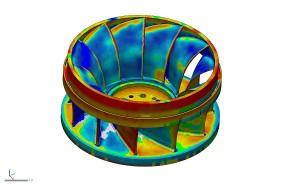
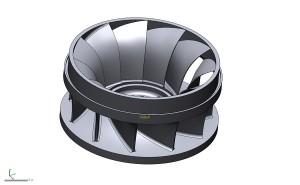
As part of a study on the possible geometric distortion of carbon fiber composite parts, and with the help of a HandySCAN 3D device, EADS scanned 1,000 mm x 800 mm tools, as well as 650 x 300 mm parts, in order to evaluate possible deformations after manufacture.

Tool Parts

First, EADS scanned the tools to verify that they met the CAD plan.

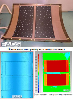
Escaneado de herramientas con el HandySCAN 3D

Two of the parts made with this tool were then scanned and the results compared.

Scanning Parts and Results

The second step was to use very powerful simulation tools to calculate the distortion of the parts before they were manufactured, with the aim of comparing the files of the scanned parts.
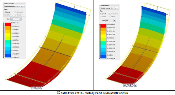
Simulación

Simulation

The results obtained by EADS allowed to validate the simulation software, developed to optimize the manufacturing range by identifying appropriate parameters and processes.

This project could have been carried out with a peripheral projection scanning system, but the system of these characteristics that EADS possesses cannot be used on such wide surfaces, and the process is much more complex when the two sides of the composite parts are to be measured. In addition, a CCM scanner could have been used, but this option had several drawbacks, as unique measurements had to be made which, in turn, lead to a much longer acquisition time.

“The Creaform system allowed us to quickly scan metal tools and carbon fiber composite parts. Many of the systems available on the market do not work very well with these composite parts, since they are dark in color and sometimes quite bright. The fact that the equipment was portable allowed us to perform measurements at the same manufacturing plant,” explained Catherine Bosquet of EADS’ Healthcare Engineering Department (NDT &shm).

“Before using Creaform systems we used peripheral projection equipment, as we acquired a HOLO3 system more than 15 years ago. We also tested some of the available systems (Konica Minolta, Metris, Steinbichler, Aicon, Kreon Technologies, Ettemeyer, GOM), but Creaform’s 3D measurement solutions convinced us thanks to their rapid acquisition and configuration, ease of use, performance in measuring many types of surface states and portability. He is in charge of the management, strategic direction and development of the entire Creaform Group, as well as its offices around the world.”

Reverse Engineering an Impeller Made Easy with Geomagic Design X

Product: Geomagic Design X
Industry: Industrial Machinery and Heavy Equipment

When small business owner Matthew Percival of 3D Rev Eng was contracted by Dependable Industries, a pattern and tooling shop in Vancouver, British Columbia, to assist in the reverse engineering of a power generation Francis Runner casting, the full power of Geomagic Design X was put to the test.

Percival had a very finite, one-day window of time to 3D scan the part. There was no drawing to confirm against, so he had to be able to work quickly and accurately. The working runner that was being reversed engineered was on its last repair cycle and needed to have a replacement casting ready in one year. The scan data was acquired in about four hours using a hand held scanner.

The deep narrow pockets of the hydraulic passages limited the scanner’s range and made complete data acquisition impossible. With about 85% of the part scanned, Percival knew he had enough to make a complete CAD model using the software from 3D Systems.

CAD model using the software from 3D Systems.

“For me, Design X is the obvious software choice. The ability to generate solid models directly on the scan data is priceless.”

Matthew Percival of 3D Rev Eng

Using the data live on site, Percival was able to create sketches and smooth lofted surfaces between the two sides of the acquired data and conform it to the casting using hands on methods in Geomagic Design X. Doing this revealed a number of interesting details to the customer:

  • The center axis of the impeller was no longer square to the
  • vanes which results in an unbalanced and inefficient part
  • The cast surfaces were badly worn and out of typical tolerance
  • The volume of each cavity was inconsistent
The impeller Scan inside Geomagic Design X

Design X easily overcame these issues. Percival was able to generate sketches on the blade, as well as an accurate smooth surface that he could revolve around the extracted revolution axis. The surface was then trimmed to match the profile and revolved to obtain the proper count of blades. Comparing this data live with color deviation maps to the scan data, Percival was able to ensure that accuracy was within the client’s requirements.

The problem of the part not being on the center axis was easily fixed, since Design X allowed Percival to redesign with design intent. He was able to model the part by extracting the profile, generating a sketch and adjusting the revolution axis to the proper design intent. Lastly, he merged the model and extracted the radii from the scan data, applying it to every blade. Once the model was complete in Design X, he used the software’s LiveTransfer technology to send the entire feature-based solid model into Solidworks and saved it as a native sldprt file for the client.

Using the CAD tools in Design X and the product knowledge provided by the customer, Percival was able to recreate the entire runner as a solid model true to design intent.

Cost savings in decreased downtime of hydro power generation plant

$ 20,000 per day *

Average cost to traditionally reverse engineer a runner

$ 3,800 and 4 days

3D Rev Eng cost

$ 2,500 and 2 days

Cost to manually produce foundry tooling from traditional reverse engineering data

$ 35,000 and 5 weeks

Cost to CNC cut foundry tooling from CAD data made in Geomagic Design X

$22,000 and 3 weeks

Cost savings in finish machining and balancing of a casting made from CNC tooling

$ 3,500

Cost savings and power generation efficiency resulting from highly-accurate hydraulic passages and balancing

UNLIMITED

Conclusion

The successful completion of the Francis Runner project has opened the door for other impeller projects for Percival and 3D Rev Eng. These projects include aquaculture impellers, mining impeller blades and Pelton wheels. Geomagic Design X allows Percival to quickly use complex shapes and surfaces to produce models within hours, which would otherwise have taken weeks.

Protocast Cuts Leadtime on High Value Casting Patterns

Product: MJP 3D Printer
Industriy: Casting

Established in 1966, Protocast-JLC is a one-stop precision investment casting manufacturer for a variety of quality- and innovation-oriented industries, including aerospace, energy, communications, medical, and military, among others. The full-service investment casting foundry has built a strong reputation among its customers for its ability to tailor production to meet customer demands, and the addition of a ProJet® MJP 2500 IC investment casting printer by 3D Systems has contributed to that reputation. In addition to helping the foundry deliver intricate, high-quality investment casting patterns faster, the flexibility of digital production has enabled Protocast to win more customers by providing a cost-effective way to fulfill orders of any volume.

Intricate, high-quality 3D printed investment casting patterns, delivered fast

Protocast specializes in the pouring of aluminum, steel, and copper-based investment casting alloys and has built a reputation among its customers for successful casting outcomes on unique parts that would be impossible to tool and injection mold. These parts include thin walls and intricate details. For example, amplifier horns on satellites, which have “hyper-thin walls” that could not be done any other way, according to Chris List, Business Development Manager at Protocast.

Protocast has built this reputation through the incorporation of additive technologies for 3D printing casting patterns. Foundry owner John List began incorporating additive technologies through third-party providers as a way to help his customers achieve more intricate parts and bypass the design limitations typical of conventional casting pattern production. However, outsourcing pattern production made it challenging for Protocast to fully set and control delivery schedules, which typically hovered around twelve to thirteen weeks when relying on a vendor to supply the pattern.

To improve self-sufficiency, predictability, and costs, Protocast purchased 3D Systems’ ProJet MJP 2500 IC, to produce castable 3D printed parts in-house. Since integrating its own 3D printer, lead time from order to delivery has shrunk from multiple months to same-week delivery.

A streamlined workflow from CAD to casting

Interior of metal cast part created by Protocast using 3D Systems ProJet MJP 2500 IC

According to Chris, who is Protocast’s primary operator of the ProJet MJP 2500 IC, 3D Systems’ digital foundry solution has helped the foundry remove steps from its previous process, particularly in aluminum castings and for detailed parts. Using conventional methods, some of the parts Protocast produces would require two to four tools to produce. “Now, we can get something printed and in someone’s hand in a week if we have to,” says Chris.

The ProJet MJP 2500 IC is a 3D printing solution for the digital foundry that uses 100% RealWax™ investment casting wax to deliver fast and cost-effective, tool-less wax patterns. By eliminating tooling, the ProJet MJP 2500 IC reduces the time and expense of transitioning from a design to a cast part, and 3D Systems’ VisiJet® M2 ICast material, a paraffin-based wax, integrates seamlessly into standard investment casting workflows. It is now possible to produce high quality cast parts in a fraction of the typical time.

The ProJet MJP 2500 IC has been a great tool for Protocast, particularly in steel castings, and performs identically to the foundry’s existing processes. Chris says the foundry is getting reliable casting results with its in-house 3D printed patterns simply by calculating shrink rates and applying them to the geometry in 3D Sprint®.

“Our customers have responded very well to these parts, and I think the time and cost savings enabled by this process contribute to that response,” Chris says. “Taking a drawing and turning it into metal has traditionally been a drawn-out process. The immediate satisfaction of holding a physical part is awesome.”

Exterior of metal cast part by Protocast produced using 3D Systems ProJet MJP 2500 IC

Transitioning to the digital foundry

Protocast reports an easy transition to the digital foundry and is now able to defy conventional limitations on casting pattern production in terms of both complexity and speed. Operationally, the main difference between life before the ProJet MJP 2500 IC and life with it, is that the foundry no longer needs to outsource casting patterns to other facilities. “We were used to using 3D models for our projects, and the software is easy to use,” says Chris, who uses 3D Systems’ 3D Sprint® software that comes with the ProJet MJP 2500 IC primarily for splitting patterns and engineering. “It’s just really easy. You can’t put it any other way,” he says.

As for the 3D printer itself, Chris says it has proven to be a valuable tool for more than final pattern production: “The machine hasn’t stopped running since we got it,” says Chris. In addition to production patterns, Protocast uses its ProJet MJP 2500 IC to produce scaled-down versions of customer parts to aid in both quoting and sales. “This capability has been very beneficial because it shows our customers we are able to get started right away, and it also gives us common ground to have engineering discussions as needed.”

Faster time to parts, high quality casting patterns, and enhanced customer communication are all great advantages. The biggest advantage of all, however, has been growth: “I think the ProJet MJP 2500 IC has opened up a new customer base for us,” says Chris. “Before, we weren’t able to accommodate as many jobs that needed flexible production quantities. Now, we don’t have to wait for any tooling and we don’t have to add twenty thousand dollars in tooling to the quote we give our customers.”

Reliable access to casting

Given the success of integrating the ProJet MJP 2500 IC into its workflow, Protocast is now considering the purchase of additional machines to continue growing its capacity and providing its customers with enhanced service.

“Managing how we’re going to produce parts is a huge deal for us and our customers,” says Chris. “The ProJet MJP 2500 IC has given us a reliable solution in that regard, and that is in addition to its ability to help us with near-instant parts-in-hand and fast quoting. It really is an amazing tool to have.”

“Good toolmakers are hard to find,” says List, “but we’ve found one with this machine.”

ADIRA introduces a new additive manufacturing process for large-scale parts

Product: Solid Edge
Industry: Industrial Machinery

ADIRA, based in the Porto area of Portugal, has a long history of success in the design and manufacture of sheet metal machinery. Its products include press breaks, shears, laser cutting systems and custom solutions. ADIRA sells its machinery in 60 different countries where it is used by manufacturers in many different industrial sectors. ADIRA’s most recent approach focuses on additive manufacturing with the development of a radical new powder bed fusion system, the AddCreator.

Additive Manufacturing with Powder and Bed Fusion

Bed-powder fusion is a relatively recent technology that was first proposed in 1995. Use a laser or electron beam to melt and fuse metal dust. Other than sintering, the fusion of powder and bed completely melts the metal powder to produce a solid and homogeneous mass. This process can quickly and accurately create high-strength and geometrically complex components. ADIRA’s unique implementation of additive powder bed fusion manufacturing is called “laser shingle fusion”.

Unique Scaling Capacity For Large Component Manufacturing

According to Tiago Oliveira, Chief Marketing Officer of ADIRA, “A unique feature of the AddCreator is the ability to apply mosaic laser fusion to large-scale component manufacturing. We have developed a modular, mobile construction chamber that moves around the dust bed area. From a manufacturing planning perspective, larger components are divided into smaller segments. By using our patented scanning strategies, the scanning fields overlap ensuring the correct “dot” of the tiles. This results in highly accurate and homogeneous parts.”

The combination of the manufacture of large components and the accuracy of 100 microns of the laser system is giving rise to interest in AddCreator from manufacturers in different segments of the industry. An example is from the aerospace industry for the manufacture of turbine rotors. These components feature curved geometries and complex internal chambers and are very expensive to manufacture using traditional machining methods.

Using Solid Edge to Design the AddCreator

ADIRA has been using Solid Edge successfully for several years for the design of its sheet metal manufacturing machinery. They are now applying this knowledge to the development of AddCreator. The complete AddCreator machine includes structural elements, sheet metal housings, a grated system for positioning the construction chamber, and high-precision electromechanical subassemblies. According to AddCreator project manager Joao Paulo Santos, “we have created an accurate 3D CAD model of the complete machine with more than 15,000 components. Solid Edge allows us to work accurately in this very large assembly. For example, our designers can specify that certain areas of the assembly become “inactive” when they focus on other areas. This improves system interactivity for our designers.”

It also describes some of the benefits ADIRA is achieving using unique synchronous technology within Solid Edge: “Synchronous technology allows us to design faster and make changes more easily. An example of the power of synchronous technology is its ability to work with 3rd-part CAD data. One of our partners provides us with STEP files of the components they develop and manufacture for us. Using synchronous technology, we access the complete 3D design, use it in our assemblies, and directly edit smart features like holes.”

Partnering with Cadflow and Siemens

It continues, “We also receive high-quality technical support from our local channel partner Cadflow. We work with Cadflow to train in specific Areas of Solid Edge for our designers. We also participate in your solid edge-specific capabilities webinars, for example, in the design of steel structure structural elements.”

In the future, ADIRA plans to investigate additional Solid Edge capabilities. These include generative design, technical publications, electrical circuit design, and enhanced data management capabilities. ADIRA uses Siemens SIMATIC Controllers for its machines. Closer integration of the mechanical, electrical and software aspects of its designs is another area in which ADIRA sees interesting possibilities for future collaboration with Siemens.

×