Using Femap to make parts suitable for deep-space missions

Product: FEMAP, Simcenter
Industry: Aeroespacial

Siemens Digital Industries Software solution helps Almatech optimize unprecedented high-performance, lightweight component designs

Using Femap makes it easy to reiterate the simulation process.

Dr.Luc Blecha,CTO Almatech

Top precision and maintenance free reliability

To boldly go where no human has gone before was the mission of the starship Enterprise. Its aim was to explore strange new worlds, to seek out new life and new civilizations. While manned space voyages of this magnitude remain fictitious, mankind is sending out space probes to achieve these goals.

During their deep-space missions, typically lasting several years, the satellites are exposed to extreme environmental conditions. These include temperatures ranging from −160 °C to more than 350 °C and acceleration forces amounting to several g as well as high levels of various kinds of radiation. At the same time, there are no gravitational effects such as thermal convection. The on-board instruments and associated fixtures require high precision and operational reliability.

“Although they are optimized for minimum weight, their stability and functionality need to be sustained over several years without any maintenance or cleaning,” says Dr. Luc Blecha, chief technical officer (CTO) of Almatech. Employing 25 scientists and engineers, the company based in Lausanne, Switzerland, develops lightweight structures and mechanical solutions for exceptional requirements such as high precision and reliability in harsh environmental conditions. Almatech is frequently involved in the design of components for spacecraft programs of the European Space Agency (ESA).

Structural components for outer space

Scheduled for launch in late 2019, the Characterising Exoplanet Satellite (CHEOPS) will observe individual bright stars that are known to host exoplanets. It uses a photometer on its telescope to measure the dimming of the starlight caused by a transiting planet. It will provide scientists with the high-precision transit signatures that are needed to measure the sizes of small planets. This data will provide key insight into the formation and evolutionary history of planets.

As part of the Swiss-managed CHEOPS project, Almatech was in charge of all the structural components. The task involved the design and construction of the tubular main structure made of carbon fiber reinforced plastics (CFRP) as well as titanium brackets and the junctions holding the primary and secondary mirrors. The mirrors cannot be adjusted in flight, so their support needs to be rigid and have high stability over the range of temperatures experienced in space.

BepiColombo, a joint European and Japanese mission to Mercury, is already on its way to our inner neighbor. Launched in October 2018, it will start orbiting the least understood planet in our solar system in late 2025. The mission comprises two spacecraft: the Mercury Planetary Orbiter (MPO) and the Mercury Magnetospheric Orbiter (MMO). While gathering data during its one-year mission, the MPO will endure temperatures in excess of 350 °C.

Almatech designed and optimized a baffle that protects the MPO against heating to more than 270°C. It also protects the laser receiver of a built-in altimeter against the heat coming from the sun. The components included a very fine aluminum mirror used to deflect rays of sunlight. “The shape of this mirror was given, the tolerable roughness was specified at 4 nm, regardless of any external influences,” says Blecha. “By comparison, the diameter of one aluminum atom is 0.25 nm.”

The Solar Orbiter is a collaborative mission between the ESA and the United States’ National Aeronautics and Space Administration (NASA) to study the sun and its outer atmosphere. Scheduled for launch in 2019, the spacecraft will observe the sun’s atmosphere and combine these observations with measurements taken in the environment surrounding the orbiter. It will provide insight into fundamental physical processes studied under conditions that are impossible to reproduce on Earth and unfeasible to observe from astronomical distances.

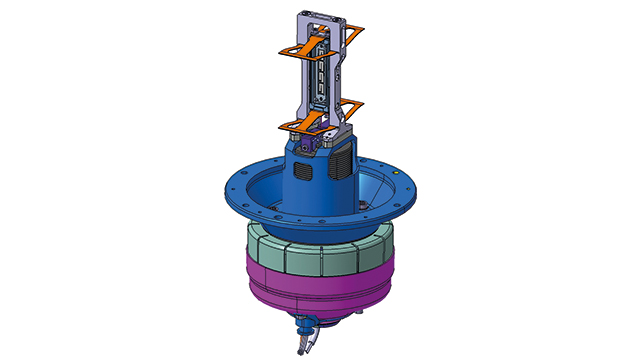
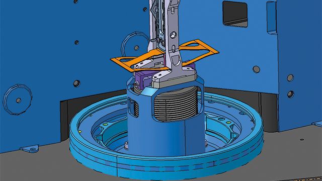
A Spectral Imaging of the Coronal Environment (SPICE) instrument aboard the Solar Orbiter will observe both the solar disk and the corona to characterize plasma properties at and near the sun. For this instrument, Almatech designed a slit-changing mechanism. It moves the shutter by deforming parts rather than sliding along guiding tracks. “This is vital because particles created by abrasion would over time disable the optical instrument, and cleaning is impossible,” says Blecha.

Testing the digital twin again and again

For many parts, Almatech’s role is to optimize existing designs. The CHEOPS telescope structure, for instance, needed to be reduced in complexity and weight while retaining its structural strength. “Because all components we create are unique and need to function for many years without any maintenance or cleaning, development cycles take longer than in terrestrial designs,” says Blecha. “Although the shape of the baffle for the BepiColombo orbiter was given, it took us four years to arrive at the final hardware.” Almatech spent a similar period developing the slit-changing mechanism for the Solar Orbiter, although they were contracted to provide the entire development from first idea to final hardware.

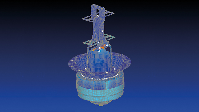
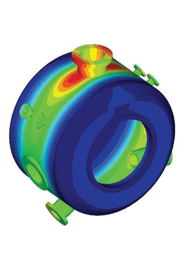
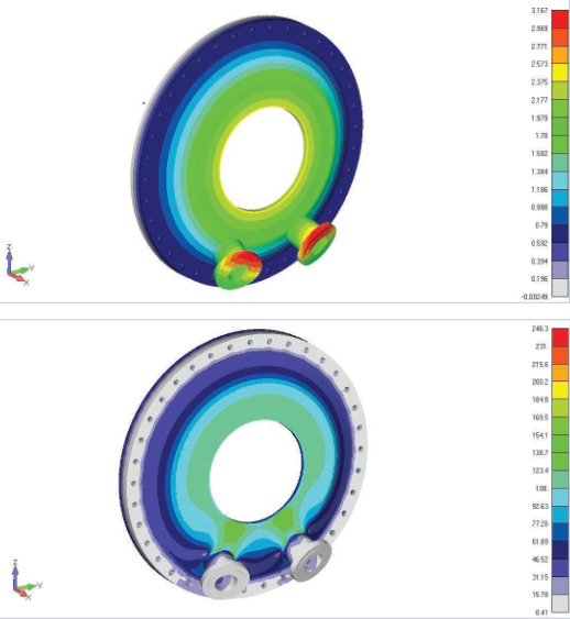
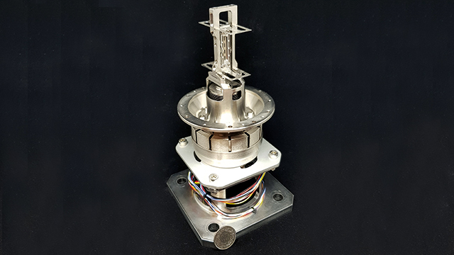
The main cause for these extended development cycles is the enormous number of tests performed to deliver proof that all requirements will be met in all fathomable situations over the entire lifecycle of the components. Within a development cycle, several physical prototypes are built and tested as well, but Almatech performs the vast majority of these tests in the virtual world using a digital twin of the component under scrutiny. For this purpose, the space-grade equipment designers use Femap™ software from Siemens Digital Industries Software in conjunction with the Nastran® solver to simulate performance, starting at very early phases of product development. “The various model analyses provide proof to clients and authorities that the complex devices will perform as required under the anticipated conditions,” says Blecha. “They are also instrumental in our efforts to reduce mass without compromising stability.”

Enhancing lifetime battery modeling for longer-life green vehicles

Product: Simcenter
Industry: Automotriz y Transporte

The Simcenter Amesim Electric Storage library is of great help to renewable energy and automotive industries players. This allows design engineers to make the right technical and economical choices in the right time schedule.

Eric Prada, Ph.D., Electrochemical R&D Engineer, IFPEN Electrochemistry and Materials Department

Greener, more reliable and cost-efficient technologies

Reducing carbon dioxide (CO 2 ) emissions is a major challenge facing the world’s auto- makers. To address this issue, manufacturers have developed new technologies such as hybrid electric vehicles (HEV), plug-in hybrid electric vehicles (PHEV) and pure electric vehicles (EV).

The success of these technologies hinges on the efficiency of energy storage sys- tems such as batteries and ultra-capacitors. These components are expensive, and it is difficult for original equipment manufac – turers (OEMs) and battery manufacturers to master and guarantee electric storage systems for more than eight years. Today, battery durability is one of the biggest problems facing the auto industry.

The fact that there are many different battery chemical technologies and aging mechanisms makes this problem even more complex. Degradation mechanisms vary greatly according to the type of chemical technology considered. Types include lithium nickel cobalt aluminum oxide (NCA), lithium iron phosphate (LFP), lithium nickel manganese cobalt oxide (NMC) and lithium titanate (LTO).

There are two different aging modes: cycling and calendar. Cycling corresponds to the battery usage when a car is moving, while calendar corresponds to when a car is parked. This cycling and calendar distribution is not the same for a passenger car as a bus or a truck. For instance, the cycling mode percentage is much higher for trucks compared to passenger cars.

Long-standing partners, new challenge

Ten years ago, Siemens Digital Industries Software started cooperating with IFP Energies nouvelles (IFPEN), a research and innovation center with strong expertise in the fields of energy, transport and environment. As a part of its innovative transport activity, IFPEN designs and enhances technological solutions to reduce vehicle fuel consumption and environmental impact.

In 2008, IFPEN started working on electric storage systems issues. Following six years of powertrain simulation partnership, many IFPEN research and development (R&D) specialists have become proficient in using Simcenter Amesim™ software, part of the Simcenter™ portfolio. Moreover, IFPEN knew that Simcenter Amesim was becoming the standard for many industry players.

The choice of partner was evident, and the initial scope of cooperation between Siemens Digital Industries Software and IFPEN was extended to battery issues. As a result, Siemens Digital Industries Software and IFPEN codeveloped the electric storage library, now available within Simcenter Amesim software, a powerful and versatile multi-domain simulation platform.

Electric storage library

The first shared achievements included in the electric storage library are focused on Lithium-ion (Li-ion) and nickel-metal hydride (Ni-MH) batteries as well as ultra- capacitors. The library consists of either generic or validated (calibrated) electrothermal models allowing for rapid and easy simulation.To calibrate models, experimental tests were mainly performed at the IFPEN battery test bench facilities. As an alternative, users can quickly calibrate empirical equivalent circuit models with their own experimental data thanks to the battery assistant tool developed by Siemens Digital Industries Software and available in the electric storage library.

The main technical challenges for the development of the electric storage library were to choose the right level of energy storage system models for end users. “We had to design and work on different modeling approaches that allow for easy and fast simulation, while still encapsulating the details of fundamental physical phenomena to ensure reliable simulation results,” says Eric Prada, electrochemical R&D engineer, electrochemistry and materials department at IFPEN.

“Our current challenge is to gain insight into electrochemical energy storage systems behavior and develop predictive and reliable mathematical models enabling engineers to rapidly build, specify and optimize energy solutions,” Prada says. “For instance, they can be used for energy storage sizing to meet power and energy performances of a targeted application for battery management systems functional design and usages strategies optimization.

As a part of its cooperation with Siemens Digital Industries Software, the IFPEN team has recently developed different modeling approaches to simulate battery degradation phenomena. IFPEN designed a dynamic electrochemical aging model able to predict the loss of autonomy degradation for a specific Li-ion battery technology (LiFePO4/graphite). IFPEN’s advanced electrochemical and analytical testing facilities made it possible to calibrate electrochemical models by measuring the main geometrical, electrical and physicochemical cell parameters. Then those predictive models were validated on a wide database built up on the basis of in-house cell tests and test results available in the literature.

Thanks to these studies, 10 years of battery behavior can be analyzed in only a few hours. This validated model can be used to analyze the impact of usage strategies for the vehicle (monitoring the SOC for the PHEV) or for the vehicle-to-grid (V2G) technology. “The Simcenter Amesim Electric Storage library is of great help to renewable energy and automotive industries players,” says Prada. “This allows design engineers to make the right technical and economical choices in the right time schedule.

Pressure equipment design specialist Ener Consulting achieves reliable results using Simcenter Femap

Product: Femap, Simcenter
Industry: Industrial Machinery and Heavy Equipment

Ener Consulting automated the finite element analysis of pressure vessels in conformity with European and international standards

Verifying designs of pressure equipment

Ener Consulting – Integrated Technical Services (Ener Consulting), founded in 2002 and with headquarters in Prato, Italy, offers engineering consulting to industrial customers. The company’s mission is to work with dedication, to stay abreast of technological developments and to provide customers with reliable results. One of the core services of Ener Consulting is the verification of pressure equipment, exchangers, piping and vessels in the oil and gas, power and chemical industries. Over the years, the business has been gradually extended to other industries, including pharmaceuticals, food, pulp and paper, waste processing and many others.

“The design of pressure equipment has evolved over time for the type and complexity of analysis, requiring high-level specialization and analysis skills,” says Stefano Milani, finite element modeling (FEM) manager at Ener Consulting. “Until the mid-1990s, finite element analysis was regulated by loose standards; there were just a few guidelines with no proven procedures. Customers did not have extensive know-how, and without clear procedures, virtually all verifications of pressure vessels were based on manual calculations.”

Automated analysis with  Simcenter Femap

In the 2000s, the pressure vessel sector made quick progress with the introduction of standards and technology tools to automate analysis tasks. In this context, Ener Consulting started to collaborate with a Siemens Digital Industries Software Solution Partner for Simcenter 3D, Simcenter Femap and Nastran solutions. After using basic FEA software that could not perform accurate analysis and deliv-ered unreliable results, Ener Consulting identified Simcenter™ Femap™ with Nastran® software from Siemens Digital Industries Software as a suitable solution for implementing engineering, analysis and design services, and keeping up with the requirements of target markets.

“Traditional FEA tools that are integrated in 3D CAD software are very simple and intuitive,” Milani says, “but they have limited capabilities and are inadequate to execute accurate analysis in conformity with the strictest standards or in-depth verification. Simcenter Femap offers clear and tangible benefits in terms of speed, ease of use and reliability of results.”

The analysis conducted by Ener Consulting begins from 3D models with relatively complex geometries that are difficult to address with general-purpose FEA software. With Simcenter Femap, Ener Consulting engineers can readily clean the geometry, eliminating unnecessary features for analysis purposes (defeatur-ing). Alternatively, the equipment to be analyzed can be modeled directly in Simcenter Femap as a mesh.

Ener Consulting, developed an add-on module for stress linearization in Simcenter Femap. “With this plug-in, engineers need only a couple of clicks on the screen to get the results they are looking for,” says Francesco Palloni

“The end customers in our reference markets need to check products with a quick and reliable method,” Milani says. “Simcenter Femap helps us deliver the desired results following either a tradi-tional approach or a more modern and advanced method.” The benefits of nonlinear analysis

For the structural verification of pressure vessels, a traditional design-by-analysis approach (stress categorization) often results in component oversizing, because the conventional linear static analysis approach, while proven and easy to apply, is conservative. Engineers must also consider that the linear analysis procedure is articulated and time-consuming when applied to complex geometry. Currently, pressure equipment regulations allow the application of more accurate analysis methods, including using tools such as Simcenter Femap with Nastran for non-linear calculations.

“The ASME boiler and pressure vessel standard, for instance, allows for checking pressure vessels using a nonlinear consti-tutive equation,” Milani explains. “On one hand, it forces the analyst to introduce a more complex constitutive equation in the mathematical model; on the other it requires a tool like Simcenter Femap with  Nastran to solve this type of analysis,” Milani explains.

“The Simcenter Femap nonlinear approach offers a wider admissibility range,” Palloni adds. “With the same geometry and materials, a component can offer higher performance than those predicted with elastic linear analysis. Another benefit is obtained in the postprocessing phase, which is faster and immediate.”

The effectiveness of the Simcenter Femap nonlinear approach was proven in the case of a vessel with a flat bottom of variable thickness. When analyzed with a conventional linear analysis procedure, the component did not pass the elastic test; however, it proved suitable and compliant with applicable standards when it was checked with a nonlinear approach.

The linear approach to pressure vessel verification is constrained by significant design loads which, combined with linear stress analysis methods, results in the noncompliance of the design.Consequently, the initial geometry has to be modified or the load values have to be reduced to fit into the admissible range. Using Simcenter Femap with a nonlinear analysis approach requires more computing power than linear calculations and greater attention to plastic collapse, but offers a more immediate verification of the structural integrity of the pressure equipment.

Miele: A better way to make medical instruments come clean

Product: Simcenter
Industry: Medical and Forensic

A world leader in premium domestic products

Founded in 1899, Miele is a world leader in premium domestic products such as cooking, baking and steam-cooking appliances, refrigeration products, coffee makers, dishwashers, laundry and floor care products. Miele also produces specialized dishwashers, washer-extractors and tumble dryers for commercial use as well as washer-disinfectors and sterilizers used in medical and laboratory settings.

In its efforts to continuously improve its product lines, the company was particularly interested in improving the development of its washer-disinfector machines. “The major development challenge with washer-disinfector machines is the variety of items that need to be cleaned,” says Tobias Malec, development engineer at Miele. “Each piece of every medical instrument has different cleaning requirements. Some things only need cleaning on the surface. Other items, such as hollow instruments, need to be cleaned both inside and out. Different water pressures are needed in each case.”

Working with special racks

Due to these requirements, a special rack is tailored to every item that needs cleaning to enable the best possible handling and hydraulic performance. Each rack secures the items being cleaned, and includes the hydraulic connections between the circulating pump and the nozzles through which water sprays. The variety of racks makes it difficult to harmonize the entire production system.

It is essential to adapt the frequently changing hydraulic conditions of the rack, and to understand the cleaning pressure required during the operating state inside each rack. The cleaning pressure results from the intersection point of the hydraulic resistance curve of the rack and the characteristic of the circulating pump.

For this engineering challenge, Miele uses Simcenter Amesim™ software, a mechatronic system simulation solution part of the Simcenter portfolio from Siemens Digital Industries Software. This solution helps Miele engineers simulate the operational characteristics of new products early in the design stage, revealing ways to improve functionality while reducing the need for physical prototypes. “Using Simcenter Amesim enables us to model the racks as super components, with the circulating pump operating as a characteristic and the washing machine itself as a system boundary,” says Malec. “Thanks to the system simulation, we can evaluate future operating points by changing the geometries of the cleaning nozzle or the water lines.”

He notes, “Using this software, we are now much more effective in the predevelopment phase. Before, without the support of Simcenter Amesim, we had to build a real prototype of the washing machine and perform multiple pressure measurements. Afterwards, based on the pressure results, we needed several redesign loops in the prototype phase to reach the required specifications. This was very time-consuming and costly.”

A typical model prepared using Simcenter Amesim includes hydraulic and hydraulic-resistance components. The machine is modeled, including its water lines and the circulating pump. The water lines include back-pressure valves and a coupling with the rack models. Some nonstandard valves have been customized and are represented by generic elements, such as orifices or T-junctions, which are validated by internal measurements.

A cleaning rack consists of a network of jets and pipelines connected with two coupling points of the machine. To ensure that compatibility and clarity are quickly achieved, the rack is integrated into the model as a supercomponent and is represented with an icon.

Mechatronic system simulation is the key

The various pumping rotation speeds are then tested virtually. This allows Miele to investigate the pressure evolution on pre-defined sensor positions to validate the simulation model. The machine operating state is quasi-static, so dynamic examinations are negligible for those types of investigations. The simulated pressure values provide the basis to make adjustments in rack design.

“System simulation enables us to easily study the impact and interactions of crosssection changes,” says Malec. “Changeovers can be optimized or nozzle parameters varied to achieve a more constant pressure distribution. Constant pressure distribution enables good cleaning capacity in all parts of the machine.”

The design exploration capability also helps establish consistency for the spray arms. By setting targeted boundary conditions and defining degrees of freedom (DOF), the optimal nozzle configuration can be found quickly using Simcenter Amesim. “System simulation is an extension of the common 3D computational fluid dynamics (CFD) simulation on a subsystem level,” says Malec. “Correlations become clear very rapidly. Without system simulation, these correlations can only be realized using measurements on expensive prototypes.”

Malec concludes, “The longevity and high quality of our products address the sustainability issue. Our customers don’t have to buy a new machine every few years, but can rely on our consistent quality. That doesn’t just save money, it is also good for the environment. We are also reducing our consumption of resources and using ecologically sound materials for production.”

IHC Handling Systems improves virtual prototypes and ultimate quality of offshore equipment; tight integration of Simcenter Femap and Solid Edge makes it possible

Product: Femap, Simcenter
Industry: Consumer Products and Retail

With Simcenter Femap, company increases re-use of proven designs, boosting productivity and decreasing costs.

The need for virtual prototypes

In the offshore industry, operational certainty is one of the most important requirements. The installations are large and the investments are high. Virtually everything is unique and leaves little room for error. As a supplier of tools for the installation of offshore equipment, IHC Handling Systems v.o.f. (IHC Handling Systems) is very familiar with the market. Functionality and quality must be validated prior to production. Virtual prototypes are the only way to ensure this.

IHC Handling Systems is part of IHC Merwede, a world leader in the dredging and offshore industry. IHC Merwede’s products include dredging vessels, equipment and components, as well special-purpose vessels and technology. IHC Handling Systems focuses on products for oil, gas and wind, such as equipment for pipe laying, equipment for the installation of oil and gas rigs and equipment for the installation of offshore wind mills.

Quick response and communication

In order to lay pipelines on the seabed or put piles of windmills upright, the thin-wall, tubular pipes need to be picked up by grippers. These are metal clamps that are placed on the inside and outside of the tube. The force with which the clamps grip the steel enables the lifting of the product. For the leveling of oil rigs, IHC Handling Systems provides equipment to establish a temporary connection between the seabed construction and the jackets on which the platform rests. Most of the products produced are project-specific. IHC Handling Systems usually has an early involvement in new offshore projects. “Customers approach us because of our reputation and experience,” says Cor Belder, concept engineer at IHC Handling Systems. It is important to have certainty about the concept solution in an early stage. A quick response to customer demands and communication are essential. “At the same time, we also want to offer functional certainty. That can only be achieved using advanced and integrated design tools.”

Lower cost of software

A few years ago, IHC Handling Systems purchased licenses of Siemens Digital Industries Software’s Solid Edge® software, a comprehensive hybrid 2D/3D computer-aided design (CAD) system, and Algor® Simulation software (which is currently owned by Autodesk and is offered under the name Autodesk® Simulation Mechanical) for finite element analysis (FEA). Both solutions were bought through Bosch Engineering, a Siemens Digital Industries Software partner. “Together with a sister company in the IHC Merwede group, we were forerunners in using Solid Edge,” says Belder. “Algor worked nicely together with Solid Edge, and data transfer between the two applications allowed for quick analysis of design alternatives.” But in a recent reassessment of the computer-aided engineering (CAE) applications, Belder saw room for improvement, specifically in the areas of data integration, meshing and programming.

“Early on in the evaluation, we developed a preference for Simcenter Femap,” says Belder. “Simcenter Femap offers a significant improvement in functionality over Algor at lower software costs. We want to spend our time on the evaluation of alter-native designs and don’t want to lose it over issues related to data transfer. Simcenter Femap and Solid Edge are tightly integrated, which saves time and reduces risk.” Belder notes that in addition to the robust geometry exchange, the mesh is more constant and allows for better local refinement.

Fast iterations

In a typical project, the concept engineer develops new models or combines and re-uses existing ones. “Concepts are almost always modeled in Solid Edge,” says Belder. “In the early stages, these are simplified designs focused on functionality, but ready to be used in preliminary CAE analyzes. The integration of Simcenter Femap and Solid Edge allows for fast iterations in this concept phase.” These functional concept designs are also used for client communication.

IHC Handling Systems uses both the linear and the nonlinear functionality of the NX™ Nastran® software solver embedded in Simcenter Femap™ software. The linear functionality is used for all static calculations as well as for contact analysis. Contact analysis is often used for designing lifting tools, where steel friction pads are pressed on the inside and outside of the pipe or pillar using hydraulic cylinders. The nonlinear analysis is used for the calculation of the friction between the steel pillar and the friction pads. This friction is the basis of the grip needed to lift the pillar or pipe. The amount of friction is defined by the pressure exerted on the cylinders. At the same time, the pressure should not lead to deformation of the pipe. “These are complex calculations taking up to 20 hours,” notes Belder. “We need to find the technical and economical optimum, in other words, the functionality must be ensured at the lowest cost possible. We take the calculations to the elasticity limit of the material.”

Re-use of proven designs

The re-use of meshes and load cases saves IHC Handling Systems a lot of time, especially in projects where existing concepts can be used, even though there may be many possible variations. An example is the upending tool that is used for lifting pillars. Upending tools must be able to handle many different diameter/wall thickness combinations and must be able to pick up pillars with diameters up to 6,000 millimeters. The customer specifies the diameter of the pillar and the lifting capacity of the available crane. To find the most economical solution, the engineer would traditionally select variants and perform the necessary calculations. This implies that, for every variant, the generation of the mesh and the application of the load case are required to perform a single calculation. The geometry of the variants differs too much to re-use the mesh and load case.

Using the programming capabilities of Simcenter Femap, the CAE model can be configured and generated automatically, for example, from Excel® spreadsheet software, including the mesh and the load case to be analyzed. Moreover, programming with Simcenter Femap is easy to learn. “Using the traditional way of working, we would be able to analyze only three combinations a day,” says Belder. “Programming in Simcenter Femap saves us a significant part of the time needed for modeling, meshing and applying the load case. The preparations can be reduced from hours to minutes. We can respond much quicker to changing customer requirements.” According to Belder, building the application of the upending tool took, all in all, no more than a week: “The investment has already paid for itself, because we always need to do calculations in projects for upending tools, which we use often in our projects.”

The goal to work better, faster and more cost-efficient using Simcenter Femap has been achieved. “We were satisfied with the engineering tools we had, but there is always room for improvement. Using Simcenter Femap allows us, better than ever before, to serve our customers with our experience and quality,” concludes Belder.

Jet Propulsion Laboratory NASA engineers used Simcenter Femap to ensure Curiosity could endure the “Seven Minutes of Terror”

Product: Femap, Simcenter
Industry: Aerospace and Defense

Simcenter Femap helps optimize component and parts for Curiosity’s mission to Mars, the most challenging and demanding ever.

Sending a package to Mars is a complex undertaking

Delivering a roving science laboratory from Earth to the planet Mars requires meticulous planning and precision performance. You only have one chance to get it right: there’s no margin for error. Engineers and scientists at NASA’s Jet Propulsion Laboratory (JPL) at the California Institute of Technology had to make crucial decisions thousands of times over a multi-year product development schedule to successfully land the Mars Rover “Curiosity” on the floor of Gale Crater on August 6, 2012.   They’ve been doing rocket science at JPL since the 1930s. In 1958, JPL scientists launched Explorer, the first US satellite to orbit the Earth, followed by many successful missions not only near Earth, but also to other planets and the stars.

JPL engineers use a toolkit of engineering software applications from Siemens Digital Industries Software to help them make highly informed decisions. A key component in this toolkit is Simcenter™ Femap™ software, an advanced engineering simulation software program that helps create finite element analysis (FEA) models of complex engineering products and systems and displays solution results. Using Simcenter Femap, JPL engineers virtually modeled Curiosity’s components, assemblies and systems, and simulated their performance under a variety of conditions.

From 13,000 to 0 mph in seven minutes Also known as the Mars Science Laboratory (MSL), this rover is massive compared to earlier vehicles NASA has landed on the “Red Planet.” In the deployed configuration with the arm extended, the rover is 2.5 meters wide, 4.5 meters long and 2.1 meters high. Weighing nearly a ton, the Curiosity rover is five times the mass and twice the length of its predecessors, which meant that an entirely new and much softer landing procedure had to be engineered. NASA needed to slow the rover spacecraft from a speed of 13,000 miles per hour (mph) to a virtual standstill to softly land the rover during what NASA calls “Seven Minutes of Terror.” After completing a series of “S” maneuvers, deploying a huge parachute, and then with the unprecedented use of a specially designed “sky crane,” the MSL was gently set down so as not to damage the labs’ functional and scientific components.

Those components include a 2.1 m long robotic arm, which is used to collect powdered samples from rocks, scoop soil, brush surfaces and deliver samples for analytical instruments. The science instruments on the arm’s turret include the Mars Hand Lens Imager (MAHLI) and the Alpha Particle X-ray Spectrometer (APXS). Other tools on the turret are components of the rover’s Sample Acquisition, Processing and Handling (SA/SPaH) subsystem: The Powder Acquisition Drill System (PADS), the Dust Removal Tool (DRT), and the Collection and Handling for Interior Martian Rock Analysis (CHIMRA) device.

Curiosity also inherited many design elements from the previous Mars rovers “Spirit” and “Opportunity,” which reached Mars in 2004. Those features include six-wheel drive, a rocker-bogie suspension system and cameras mounted on a mast to help the mission’s team on Earth select exploration targets and driving routes on Mars.

Virtually all of the spacecraft itself and its payload were subjected to simulation analysis using Simcenter Femap for pre- and post-processing. Simulations performed before part and system production included linear static, normal loads, buckling, nonlinear, random vibration and transient analyses. Thousands of design decisions were made using information from Simcenter Femap simulations.

In addition to the complex nature of the mission itself, engineers developing Curiosity from initial design to final delivery of components to Cape Canaveral were working against the clock. The ideal time window to send a package from Earth to Mars is a 2- to 3-week period that happens roughly every 26 months. Missing that window would have set the mission back by more than two years, so JPL engineers needed to analyze parts and components quickly and efficiently so that they could be fabricated.

The role of Simcenter Femap

Simcenter Femap is JPL’s primary pre- and postprocessor for FEA. For MSL, engineers started using Simcenter Femap early in the design stage when they were performing trade studies on various configurations or different ways to approach the mission. As the configuration matured, they used Simcenter Femap to help create the master finite element model that was used to run the various load cases.

Most of the structural analysts at JPL use Simcenter Femap either for creating or viewing the results of a FEA run. The software was used for both high level-linear analysis and very detailed nonlinear analysis. These are two very different types of analysis both using the same piece of software.

Certain jobs were simply too large for one person, and in some instances engineers had to build on the work of other people who had previously used Simcenter Femap to build FEA models. Simcenter Femap was designed as a very easy-to-use package, created for analysts by analysts who are acutely aware of what engineers need and how they work. They can pick it up after six months of non-use and be back to peak proficiency in a very short time.

Simcenter Femap was critical in performing all types of FEA on all aspects of the vehicle. Each component of the vehicle had a higher-level, loads-type model built, and these models were joined to create the full spacecraft model. JPL engineers worked through various “what if” scenarios, including as many as 37 different load cases for how the parachute would deploy during the landing process.

The Curiosity mission is not JPL’s only current project. Other missions include satellites monitoring conditions on Earth, telescopes, experiments and other spacecraft.

Planned missions include the InSight mission that will place a lander on Mars in 2016 to drill beneath the surface and investigate the planet’s deep interior to better understand Mars’ evolution. There are even plans for a proposed Mars Sample Return mission, which would collect samples from the surface of Mars and return them to Earth.

JPL engineers are currently using and will likely continue to use Simcenter Femap to help accomplish these and other missions of engineering, discovery and science.

Using NX allows design and analysis to work together more efficiently and productively

Product: NX CAD, Simcenter 3D
Industry: Aeroespacial y Defensa

For more than 30 years, ENGINEERS at ATA Engineering, Inc., (ATA), have provided analysis and test-driven design solutions for structural, mechanical, electromechanical, and aerospace products. The company has worked on a wide variety of projects, including amusement parks, biomedical devices and electronic components.

Most of ATA Engineering’s work is done in the aerospace industry, for clients such as Orbital Sciences, Lockheed Martin Space Systems, Pratt & Whitney, NASA, Jet Propulsion Laboratory, Air Force Research Laboratory and General Atomics. There is no room for errors in this job: it is critical to meet specifications accurately, while facing strict deadlines. ATA engineers often face short production runs, sometimes even for a single unit, as a satellite component. It’s forced that they do well the first time.

ATA staff have used SOFTWARE NX™ for many years. However, they recently applied the mostrecent version of computer-aided design (CAD) and computer-aided engineering (CAE) NX software to complex real-world structures using three representative cases and found significant improvements in time and effort savings during design, analysis, and upgrade cycles.

ATA engineer Allison Hutchings defines it this way: “Real-world structures have complex design definitions and challenging analysis requirements, and both are constantly changing. NX enables you to cope with changes efficiently and productively.”

Changing model parameters without recreating geometry

The first use case involved meshing an isometric grid reflector model, such as those designed for assembly on a spacecraft. Isometric geometry provides advantages for spatial structures that must be rigid, lightweight, and durable, but the large number of surfaces implies that the definition of the initial geometry of the CAD model and the CAE model can be tedious. When the design needs to be updated, such as altering the diameter, focal length, and measurement of cells in this case, “these changes can cause severe headaches,” Hutchings says. In many cases, you may need to completely recreate the geometry instead of simply updating it to incorporate the new dimensions.

Leveraging Synchronous Technology provided by NX along with an intelligent approach to the original design definition, however, these issues are avoided. Several techniques, such as patterns and expressions, facilitated the direct parameterization of key geometry definitions in NX CAD and this capability was leveraged directly for meshing and analysis. As a result, 100 percent of the geometry was automatically updated and 96 percent of the riveting was performed automatically when the associated finite feature model (FEM) was upgraded to the new geometry. Cleaning the remaining 4 percent was relatively quick and easy, particularly compared to the need to recreate FEM altogether.

The second use case was a lightweight support model. Because weight is a pressing factor in aerospace designs, the engineer must struggle with competitive goals to maintain the lightest possible support while meeting stiffness requirements while maintaining the ability to handle the necessary loads. The process often results in supports with complex geometry.

In Finite Element Analysis (FEA), the standard practice is to “idealize” geometry, eliminating details and features that do not affect analysis. It is done to save calculation time, but it is often necessary to repeat the idealization process each time the part is updated.

With NX, this additional step can be avoided. For this task, after the part dimensions were changed, 93 percent was automatically idealized and updated. Although the changes that were made to the support were relatively simple, the time and effort savings were remarkable: the automated idealization of the upgrade was more than 100 times faster than the manual process and meshing of the updated model was at least 3 times faster.

Updating geometry in minutes

The third use case focused on the model of an existing air brake: a assembly that allows an aircraft to slow down to land by generating a turbulent output flow from a fan bypass nozzle and also makes it easier to landing the aircraft slower, from a steeper angle, reducing overall noise.

The blade angles inside the air brake can have a drastic effect on the performance of the air brake under different conditions. By altering these angles in the model, the analyst can evaluate those effects. In this case, the prismatic blades were rotated to analyze configurations between 0 and 25 degrees. With NX, instead of performing a tedious manual process of reshaping the entire system, Hutchings simply changed the aspa angle parameter and was able to update the geometry in minutes, as the idealized part automatically adjusted to the new angle. Hutchings comments, “Map meshing is preserved, creating an identical mesh on the blade surfaces between all angles, then the CAD model propagates to the FEM and the mesh is updated in minutes.

In all three cases, new NX features made it possible to perform geometry updates quickly, Hutchings says. “We were able to parameterize the design definition, create a structural analysis model by leveraging the design for specific analysis requirements, updating design parameters, and propagating changes to analysis modeling much faster than would have been remodeled.”

More efficient engineering with integrated design and analysis

“These are all problems that we thought were difficult to solve before,” Hutchings says. In the past, updating the finite element model due to geometry changes would involve reshaping changes in CAD, resealing the model, and riveting to create FEM, or some very complex manual changes in meshing. Both options took quite a while. “Recent additions to NX have made these efforts much easier. The degree of connection NX makes possible between design and analysis more efficiently supports engineering compared to the use of non-integrated finite element processes,” he says.

The problems Hutchings examined illustrate the advantages of working with the integrated NX range. This is not only an improvement in the refresh rate, but also the possibility of failure between the CAD model and the finite element model is also less due to the way they are linked. “If you work with constantly changing design specifications, it’s very fast and easy to modify dimensions and change parameters with NX, without having to recreate finite element models,” he says. “This saves a lot of time and effort on tedious tasks, as well as providing confidence that the model will be updated to the correct design definition.”

×