Unique web platform and zero-touch production approach enables next-day delivery

Product: NX
Industry: Industrial machinery

Reducing lead times for small machined parts

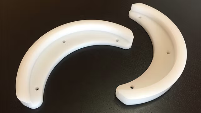
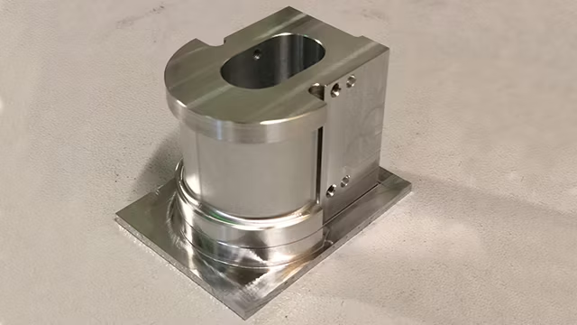
YouniQ Machining was founded in November 2017 to address a severe limitation in the machining of small fixtures and parts that are primarily used for testing and measuring. The production of such parts is typically outsourced, but production facilities are not well equipped to handle the requests. Manufacturing of single pieces typically requires eight to 12 weeks when produced with conventional machining processes. In contrast, many parts can be produced with 3D printing processes that reduce lead time to only two working days. YouniQ Machining considered whether a similar lead time reduction was possible for the machining industry.

Additive manufacturing/3D printing technologies emerged in a period when online platforms were commonly accepted; the business models of most companies that offered 3D printing services was very much focused on web-based platforms from the beginning. Industrial machining is far more conservative, but after investigating the possibilities and limitations, YouniQ Machining could not determine why time to market could not be significantly reduced.

The only limiting factors the company identified were the dimensional tolerances, which are typically much lower for machining. After some research it became evident that these tolerances are almost never a showstopper: most machine shops determine tolerances based on 2D technical drawings that specify generic and excessively tight tolerance grades from the ISO system of limits and fits that result in a tight fit. Other reasons for long lead times include overloaded production funnels, a lack of skilled personnel, unnecessarily conservative processes, and material unavailability.

Solving the problem through digitalization

YouniQ Machining’s primary challenge was to create a completely new business model that would revolutionize the production of one-time or small-batch machined parts. The company abandoned traditional approaches and reimagined the entire process from scratch, from order intake, assessment, and production to delivery. The only way to achieve this new approach was to digitalize every element of the process.

Envisioning a web-based machine shop

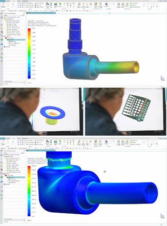
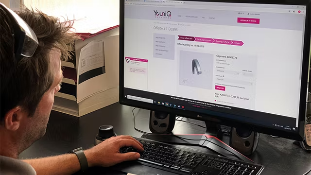
YouniQ Machining envisioned a digital workflow that could streamline and accelerate the order-to-production cycle, creating a web-based machine shop that would bring the efficiency and speed of 3D printing services to machining processes. The digital workflow begins when the customer prepares a 3D model of the desired component using any computer-aided design (CAD) program and uploads the CAD file to a web portal. Once uploaded, YouniQ applies automated routines to analyze the model’s manufacturability and generate a quote based on simulated machining time and material. The company provides the customer with a downloadable 3D model of the part showing the expected machining results, which the customer can use to verify its fit in an assembly. Customers can adjust the quote based on material, quantity, delivery, and post-machining requirements, and then place the order. Using computer-generated programs, YouniQ’s staff and modern machine shop produce the parts and arrange delivery as specified by the customer.

Unique web platform and zero-touch production approach enables next-day delivery

One of the main challenges in realizing the web-based machine shop was integrating the web environment with computer-aided design and manufacturing (CAD/CAM) solutions. Since no out-of-the-box solution was available, YouniQ had to program everything manually. A robust application programming interface (API) in the CAD/CAM solution was crucial.

YouniQ initially worked with a CAD/CAM provider that offered good web integration, but they could not meet the API requirements. Another CAM provider had a strong API but failed in web integration and CAD capabilities. The company then partnered with Siemens Digital Industries Software, which provided solutions that met all of YouniQ Machining’s requirements.

Through its NX™ product development software, Siemens offered best-in-class CAD/CAM integration and application programming capabilities that quickly exceeded those of other suppliers. Key features of NX that filled all gaps included web integration using the JT™ data format and the NX Open API for programming and customization. Together, these elements provided an open environment, excellent programming potential, and a strong CAD connection, which became increasingly important over time.

Realizing the vision through digitalization

YouniQ used Siemens’ solution to redesign conventional processes through end-to-end digitalization. The result is a process that provides customers with transparent pricing, direct feedback on producibility, finishing options, and design modifications that reduce costs and lead times. Most importantly, the streamlined digital process reduced delivery times from eight to 12 weeks to as little as two days. Furthermore, the process does not require customers to submit extensive 2D technical drawings.

Synchronous modeling accelerates design modifications

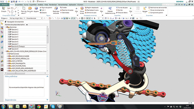
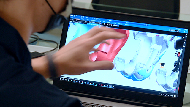
A key capability of the NX solution that enabled this reimagined process is synchronous modeling, a technology that allows direct editing of component geometry regardless of the source CAD system. Synchronous modeling eliminated the need to manually modify the original CAD design; with NX, YouniQ can easily redesign parts to ensure all specifications and tolerances match the requirements.

Automating NC programming with machining

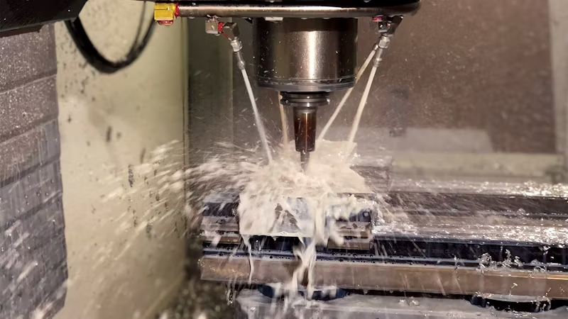
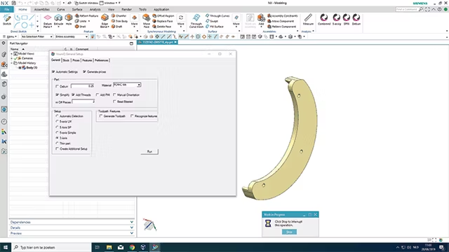
The feature-based machining capabilities of NX CAM were also crucial to the digital workflow. With feature-based machining, numerical control (NC) programs can be automatically created based on the features in the component model. A tool called the machine knowledge editor (MKE) allowed YouniQ engineers to record all the rules and tools used in machining features, capturing knowledge and data that drive automated NC programming.

Results

With its web-based machine shop and automated, hands-off workflow, YouniQ Machining reduced time-to-market from the typical eight to 12 weeks to just two days for fast delivery. The company also offers additional delivery options that reduce costs: standard delivery in five business days and budget delivery in 15 business days.

With its fully digitalized workflow, YouniQ Machining achieved higher margins than competitors, allowing investment in future innovations. The company also reduced its reliance on highly skilled experts and minimized its administrative burden, enabling the business to focus on core machining operations. With processes defined and programmed in NX, the company standardized its development procedures and enabled hardware standardization in production.

While Siemens’ NX CAM solution was a key element in achieving these impressive results, the professional support and consultation of Emixa Industry Solutions also played a significant role. With in-depth knowledge of Siemens NX CAD/CAM, automation, and postprocessing, and extensive industry insights, this Siemens Platinum business partner translated YouniQ Machining’s business needs into concrete, practical solutions. Emixa Industry Solutions’ vast experience in providing high-end technical solutions for demanding environments enabled fast and seamless implementation, minimizing downtimes and disruptions. Additionally, Emixa Industry Solutions offers a continuous feedback loop to identify and resolve future challenges and developments.

Future plans

Looking ahead, YouniQ Machining plans to add more interactivity to its web platform, including the ability for customers to add tolerances without 2D drawings and to eliminate manual product approval through advanced algorithms. The company also aims to automate the processing of product and manufacturing information (PMI – 3D annotations in part models) to support model-based design and offer a wider variety of materials.

How Supplyframe DesignLab Leverages NX X Cloud Licensing for Designing Electronics

Product: NX CAD
Industry: Electronics

What is Supplyframe DesignLab?

Supplyframe is the leading Design-to-Source platform for the global electronics value chain, offering solutions that interpret billions of signals related to intent, demand, supply, and risk, providing insights throughout the product lifecycle from design to market. In 2021, Siemens AG acquired Supplyframe.

DesignLab at Supplyframe is a physical research and development studio located in Pasadena, California. It focuses on transforming the electronics industry by collaborating with other organizations, such as universities, to develop open-source hardware projects and products with social impact. DesignLab also hosts events, including technical and university workshops.

Design Workflows at Supplyframe DesignLab

DesignLab uses NX CAD and other software from the Siemens Xcelerator portfolio throughout its design process. NX CAD offers tools for multidisciplinary, collaborative design across MCAD and ECAD, which is crucial for the design of products with electronic components at DesignLab.

The design process at DesignLab begins by gathering relevant data to guide decisions, as many of their projects are based on existing research. This might involve considering what types of sensors are needed, power management, user experience, and more. Once this information is gathered, the team starts modeling and iterating the design in NX CAD. After a design is ready, they move on to prototyping.

With NX as a comprehensive CAD/CAM/CAE tool, DesignLab also utilizes NX CAM for prototyping and manufacturing. Their 4,900-square-foot studio is equipped with high-volume Pick and Place machines, CNC mills, and 3D printers, allowing for rapid prototype development throughout the design and iteration process.

NX X: Cloud-Based Licensing for NX CAD

In June 2024, DesignLab adopted NX X, a cloud-based Software as a Service (SaaS) deployment of NX CAD for product design. NX X includes all the same multidisciplinary design tools as traditional on-premises NX CAD, plus the advantages of a SaaS solution, such as flexibility, security, and scalability. It also includes built-in data management and integration with Teamcenter PLM, which DesignLab leverages for collaboration and data sharing.

We spoke with Giovanni Salinas, Senior Product Development Engineer at DesignLab, about their decision to switch to NX X. When asked what drew DesignLab to adopt NX X, Giovanni said:

“The licensing system, easy! You practically have no license management to worry about. You just install NX X and get to work.”

The Installation Process of NX X at DesignLab

Giovanni highlighted that the installation process of NX X was “frustration-free” and the “easiest application installation by far,” taking no more than 25 to 30 minutes, most of which was spent downloading the installation package. Unlike typical software installations, which require IT team assistance, Giovanni only needed an internet connection. He received an email to download Siemens Software Center, followed the instructions, and the rest was quick, simple, and online.

“It was truly smooth. I’m seriously looking forward to more Siemens applications with an ‘X’ in their name.”

Flexibility of NX X: Desktop and Browser-Based CAD

NX X offers “the best of both worlds,” according to Giovanni. Licensing is managed online by Siemens, but the application itself remains desktop-based, allowing users to leverage their computer’s processing power.

“Other [cloud-based CAD] applications are fully online, which may make installation a breeze, but they come with their own set of challenges.”

Online-only applications are often simplified versions of their desktop counterparts, with reduced functionality and fewer capabilities. NX X, however, provides the same NX CAD features and functionalities, along with the benefits of cloud licensing. Additionally, NX X can be streamed online on any browser-enabled device through the NX X Remote Extension.

Sending it with Siemens NX

Product: NX Design
Industry: Bikes

How a mountain bike enthusiast designed and manufactured his custom carbon fiber bike from scratch with Siemens NX

Siemens is not only offering products to big companies, but also small and medium businesses and even private persons can subscribe and benefit from the Siemens Xcelerator portfolio of software and services. This is what this case demonstrates:

We recently found out about the project completed by a German mountain bike enthusiast, who calls himself Uncle Bob, and his journey that started with an empty screen and ended with custom self-built carbon fiber mountain bike.

Uncle Bob’s journey

Due to an injury from biking, Uncle Bob needed a new project to keep himself entertained. He is the founder of an engineering consultancy, which is why he owned the Siemens NX CAD software and has experience with it. So, in his free time he just started directly scribbling in Siemens NX with a try and error approach and with the following weeks, his ideas became a solid concept. 

Bob was especially delighted with the plentiful and individual 3D visualization options NX had to offer, they enabled him to work creatively and to see the realistic result of his design before building. 

Considering the design, Uncle Bob has gone for a form follows function approach: “If something already looks like something that will not last, it surely will not last during tests.” 

mountain bike in forest

Why NX?

Apart from the design aspect, he really appreciates NX for the ability to test and verify his CAD design data into finite element analysis (FEA) simulation tools, which he uses in his daily professional life as well as with this bike. “I have not regretted the investment for Siemens NX, it was worth it and definitely helped me to ease up processes. Before NX, I had to copy data manually from program to program. The implementation of NX at Daimler got me starting to look out for better solutions.” 

bike model inside of nx

So, an FEA study was done to stress test the frame and structure. After all, mountain bikes like these need to withstand high physical forces due to big jumps, loose ground and high speeds. And his bike did!

For example, his calculations resulted that the frame around the bottom bracket can withstand jumps or falls with more than 6,000N. For the areas that failed his tests, the layup of the composite material was modified in Siemens NX and additional plies were added to strengthen these areas.

Getting started and getting building with NX

bike model mold

With a flaw free concept ready, he designed an injection mold in Siemens NX that he could use for producing the carbon-fiber parts. Due to the extensive 3D features in Siemens NX, he could make the mold as material efficient and small as possible.  Then he started working in his garage: A wax core was casted that represents the inner geometry of the carbon frame. Then, he wrapped the carbon fiber around it and closed the mold airtight. Using vacuum and high pressure a hardening resign was injected into the mold. After a few hours of tempering the resign was hardened and with higher temperature the wax core melted and flowed out. Now the frame was made. He didn’t clearcoat the frame because Uncle Joe was confident enough that his construction and his materials used were sufficiently durable anyway.

After that, the frame was made and he started to assemble all the custom frame parts and bought standard parts together. A few weeks later it was all done, a extreme mountain fat bike, that all-in-all only weighted 17kg, with the NX constructed custom carbon forged frame only taking 3kg part of that. After his first test ride, Bob was beyond impressed:

“Insane! Sore muscles in the face because of the permanent grin. I can only say: Dreamy. The bike fits me like a glove.”

The strength of Siemens NX

This business case shows the accessibility, exactness and prediction powers of Siemens NX. Building something from carbon-fiber was a task that only large manufacturers would consider just ten years ago. With Siemens’ NX, now even talented designers can plan and design flaw free carbon structures from scratch at home. 

Creating custom steering wheel grips to help drivers achieve maximum racecar performance

Product: Artec Space Spider
Industry: Design and Art

Using NX reverse engineering and polygon modeling enabled design changes to be implemented and new grips produced between races, eliminating a potential on-track distraction.

Andrew Miller, Advanced Materials Engineer
Team Penske

Meeting fast-paced design requirements

Team Penske is one of the most successful teams in the history of professional sports. Cars owned and prepared by Team Penske have produced more than 600 major race wins, over 670 pole positions and 43 championships across open-wheel, stock car and sports car racing competition. Over the course of its 56-year history, the team has also earned 18 Indianapolis 500 victories, three Daytona 500 Championships, a Formula 1 win, victories in the 24 Hours of Daytona and the 12 Hours of Sebring, along with a win in Australia’s legendary Bathurst 1000 race. In 2022, Team Penske competed in the NTT INDYCAR SERIES, NASCAR Cup Series and the FIA World Endurance Championship.

In addition to racing, the company also produces racecar components and support equipment for NASCAR, INDYCAR, International Motor Sports Association (IMSA) and World Endurance Championship (WEC) racing programs.

There is a lot more that goes into winning races than just luck. Over the last decade, Team Penske has focused on developing custom steering wheel grips to help drivers behind the wheel. A custom steering wheel grip allows the driver to focus on racing, achieving maximum performance from the racecar. Clay grips are sculpted to the steering wheel frame and 3D scanned for reverse engineering, which enables Team Penske to implement a suitable design solution as fast as possible.

Team Penske achieved this by using NX™ software and Teamcenter® software, which are part of the Siemens Xcelerator portfolio business platform of software, hardware and services.nullnull

Using reverse engineering to speed up the design process

Designing these custom steering wheel grips and the necessary mold tooling is no small feat. Team Penske used to outsource the reverse engineering of the scan data, which increased costs and lead time. More recently, Team Penske used a third-party software package to reverse engineer the scan data, generate initial surface and reference computer-aided design (CAD) data. However, this data was not native to NX so making changes to the design was laborious and inefficient.

Another challenge the company faced was meeting the demands of a fast-paced racing industry. When it comes to racing, drivers are the primary stakeholders that generate results from this development. Developing custom steering wheel grips for new drivers, or implementing changes for existing drivers needs to happen within days to weeks. The fast-paced development requires Team Penske to use integrated tools to create and change designs seamlessly.null

Once Team Penske realized the new reverse engineering capabilities with the Siemens Xcelerator portfolio, they set out to use NX and Teamcenter to streamline the process. Moving the reverse engineering and design to the native NX CAD system enabled a more efficient in-house design process. Using the NX CAD system helped store all data in one location with traceability in Teamcenter. Integrating the reverse engineering process into NX with the reverse engineering tools and polygon modeling has streamlined this process. Now, Team Penske can implement changes quickly in a parametric process. This is critical when dealing with multiple INDYCAR drivers, each with unique custom steering wheel grips.

Using NX decreased the design time required to implement changes compared to using third-party software packages. One example of this comes from INDYCAR driver, Scott McLaughlin. McLaughlin wanted changes to his steering wheel grips after his inaugural season with Team Penske in 2021. Using NX reverse engineering and polygon modeling enabled Team Penske to make design changes and produce new grips for McLaughlin between races, eliminating a potential on-track distraction. “A custom steering wheel grip allows the driver to focus on racing to achieve maximum performance from the racecar,” says Andrew Miller, advanced materials engineer for Team Penske.

McLaughlin went on to win three races, capture three pole positions and finish in fourth place in the INDYCAR championship during his second season in 2022.

“Using NX reverse engineering and polygon modeling enabled design changes to be implemented and new grips produced between races, eliminating a potential on-track distraction,” says Miller.

Team Penske quickly learned how to use NX and Teamcenter with help from the online resources in the Siemens Xcelerator Academy and customer support from Siemens.null

Racing ahead

Team Penske reduced the design time of the steering wheel grips and molds from a minimum of three to four days to within one to two days. It eliminated outsourcing or third-party software requirements for steering wheel grip designs and used Teamcenter to improve design traceability for grip designs. Team Penske plans to continue using NX and Teamcenter to further investigate texturing and algorithmic modeling for applying textures to steering wheel grips and interface devices.null

A custom steering wheel grip allows the driver to focus on racing to achieve maximum performance from the racecar.

Andrew Miller, Advanced Materials Engineer
Team Penske

With NX, ÀNIMA delivers a new level of innovation, including a visually striking electric motorcycle

Product: NX CAD
IndustrY: Automotive and Transportation

We needed a cost-effective solution that suited our technical needs and worked for both Windows and Mac OS X. We were also looking for a solution that would allow us to grow by extending our potential with Teamcenter in order to monitor and manage projects in all their phases. We found these characteristics in NX.

Joan Sabata, Partner and Director

“Helping companies to innovate through design”

ÀNIMA Barcelona (ÀNIMA) is an industrial design firm founded in 2002 by Diego Quiroga and Joan Sabata. From the beginning, ÀNIMA has combined creative talent with entrepreneurial energy to help customers improve product design and new product development. The mission and values of ÀNIMA are summed up in its motto: “Helping companies to innovate through design.”

Today, ÀNIMA comprises a multidisciplinary staff of industrial designers, engineers and experts in marketing and innovation who work with a large network of international experts. This allows ÀNIMA to provide its services to companies from a wide range of industries, including automotive, sustainable mobility, machinery, industrial and personal equipment, electronics, medical products, bathroom fittings, lighting and furniture.“Helping companies to innovate through design”

The search for a high-performance CAD system

The designers at ÀNIMA were highly-experienced at modeling solid objects in three dimensions. However, they began encountering more and more projects that demanded increasing use of advanced surfaces. In addition, the company wanted to expand its client portfolio into industries in which a high-performance computer-aided design (CAD) system was crucial, enabling it to develop more complex designs. ÀNIMA concluded that its current CAD system was inadequate, and the search began for a replacement.

To begin its search, ÀNIMA consulted engineering and product lifecycle management (PLM) specialist, Análisis y Simulación (AyS), a partner of Siemens Digital Industries Software. ÀNIMA explained its needs and long term plans. AyS studied the situation carefully, taking into account both the company’s design process as well as the specific requirements of each of its departments. The selection phase included the evaluation of specific tools for advanced surface design and solid modeling in 3D. Some candidate systems were discarded because they did not support the Mac OS® operating system software from Apple.

During the selection process, ÀNIMA soon realized that a comprehensive tool was the most economical option, because it meant buying only once and maintaining a single system. The company also wanted a CAD system that avoided the problems of compatibility between different brands of software, so as to eliminate wasting time translating file geometry.

After attending several meetings and software demonstrations, ÀNIMA chose NX™ software from Siemens Digital Industries Software. ÀNIMA considered NX to be a comprehensive product development tool, calculating that its use could save the company up to 50 percent of its planned investment in the software. ÀNIMA also valued the tight integration of NX with the digital lifecycle management system, Teamcenter® software, also from Siemens Digital Industries Software. ÀNIMA plans to implement Teamcenter in the near future to improve process control and efficiency.

“We needed a cost-effective solution that suited our technical needs and worked for both Windows and Mac OS X,” says Joan Sabata, ÀNIMA partner and owner. “We were also looking for a solution that would allow us to grow by extending our potential with Teamcenter in order to monitor and manage projects in all their phases. We found these characteristics in NX.”The search for a high-performance CAD system

NX proves effective from the start

The first project developed entirely with NX was the design of the Volta® BCN electric motorcycle, which was aimed at promoting sustainable mobility in urban environments. ÀNIMA designers used NX for the entire process, from initial sketches to full development.

According to ÀNIMA management, the use of NX resulted in significant improvements in design creativity and design process efficiency. Management notes that the time needed to complete the whole design process – until the manufacture of the first prototype – has decreased by 65 percent.

“Now we know that we can tackle ambitious projects, because NX meets our high level of demand,” says Sabata. She adds, “Having Análisis y Simulación as a technology partner gives us special confidence, because of the organization’s subject-matter expertise and highly professional advice.”

With NX fully implemented, the creative team at ÀNIMA is busy developing projects for both local and international markets. Among projects, ÀNIMA is currently working on new designs for the automotive industry that will soon come to light. In fact, the design team is quite excited about the excellent impression its work will make in this market space, but moreover, the team is eager to demonstrate the value the designs will bring to its customers.NX proves effective from the startNX proves effective from the start

Scuderia AlphaTauri creates a top performing F1 car

Product: NX, Simcenter
Industry: Automotive and Transportation

The rise of Scuderia AlphaTauri

On February 23, 2022, the world got a taste of the new Formula One (F1) cars as they completed their pre-season test days in Barcelona. This was followed by testing days in Bahrain in early March 2022, where the drivers focused on getting comfortable driving the new cars before the race season began on March 21, 2022.

During the test days and the first few races, two young Scuderia AlphaTauri drivers, Pierre Gasly and Yuki Tsunoda, worked with the Scuderia AlphaTauri engineers to discover how the new car performed and fix the mistakes that occurred with the new design.

“There are new things to discover with this car every time we go out on the track so we have to make the most of each session and learn as much as we can before the first race here,” says Pierre Gasly, trackside during the test days in Bahrain in March 2022. “The feeling was unique. I was excited to discover these new cars and see how they felt on the track.”

That feel-on-the-track performance enhancer

In F1 racing, the driver and the car become one. This feel on the track comes from the part of the car that normally doesn’t get to be in the spotlight, the driver’s seat.

“The chassis is one of the most sophisticated parts of the car for safety and performance reasons. You need to start working on that part immediately even if you don’t have all of the information,” says Raffaele Boschetti, head of information technology (IT) and innovation for Scuderia AlphaTauri. “Before partnering with Siemens, we spent three months producing a good chassis. With Siemens software, we did this in one month. This saved us a lot of time and gave us many advantages.”

Aside from the chassis, the seat is important for driver safety and overall driver performance. Overall seat design is strictly regulated by F1 safety and crash test rules. If something goes wrong, drivers need to be able to exit the car quickly and safely. The safety marshal and medical teams need to be able to extract injured drivers from a crash effectively. Boschetti is quick to point out that there is much more to the seat in an F1 car than just safety.

“The seat is a part of the car that delivers performance. The driver feels all of the vibrations, accelerations and handling through the seat. On the track, we can modify the car settings to improve the car based on the driver’s needs,” says Boschetti. “In Formula One, you have a couple of tests in February or March. In this situation, the software and platforms Siemens provided us were vital to building the seat.”

One size does not fit all

Not every F1 seat is the same. Composite design engineers will tell you that half of the challenge isn’t the seat but how to fit the driver in the car.

“It is like a tailored suit. You have to look at things in terms of helmet position, back position and you have to be as low as possible,” says Francesco Dario Picierro, senior composite design engineer for Scuderia AlphaTauri.

To ensure these critical performance aspects were correct, Picierro and his colleagues developed a unique seat-designing process. To start, they designed a slightly larger seat than necessary and then heated a batch of special resin and took a physical mold of the driver’s body in the ideal position. From the resin mold, they used NX™ software to create a complete scan to design the seat. NX, the Fibersim™ portfolio and Simcenter™ software are part of the Xcelerator portfolio, the comprehensive and integrated portfolio of software and services from Siemens Digital Industries Software.

“The process might seem simple, but thanks to Siemens’ products it becomes smarter,” adds Picierro.

Using digitalization for F1 success

With the complete design and chassis change in the 2022 model, the team had to simulate every detail in computer-aided design (CAD) from overall visibility to how the driver would fit into the chassis design.

Getting the driver to squeeze in, reach the pedals and obviously see – while considering the helmet, safety regulations and the new chassis and car design – is an engineering feat in itself. The team knows that digitalization is the only way to succeed in F1 these days. Using Siemens’ digitalization tools removed most of the grunt work from the design, engineering and production cycles.

“Using NX helped us with our digitalization efforts. For example, we can replicate the exact handwork on the steering wheel or the visibility using the driver’s camera. We can also scale the digital mannequin according to the measurements of the driver,” says Picierro.

Racing against the clock

While the composite design engineers are custom fitting the driver to the seat (a process that can happen several times per season based on the needs of individual drivers) other members of the Scuderia AlphaTauri engineering team are optimizing the new car design for driver performance in time for race day.

Aside from the tight deadline, the other challenge for every F1 engineer is weight. F1 engineering teams struggled to make the minimum driver plus car weight of 795 kilograms (kg), especially with the new safety regulations and ground effect pull. At the last minute, the teams reached a compromise to increase the weight to 798 kg.

“Of course it’s always difficult. It’s a completely new regulation. These cars are complicated and it is difficult to design everything to meet the weight limit requirements. As we can see, nearly all of the teams are overweight. We also have to consider costs. It is expensive to reduce weight. Considering the cost cap, our teams were able to come to a compromise,” says Franz Tost, team leader for Scuderia AlphaTauri.

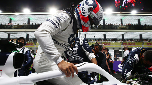
Zooming around over 300km/h during a normal F1 race, drivers experience up to four or five lateral G’s routinely under braking and cornering and during acceleration on the long stretches.

One platform and a secret to success

As Tost explained, balancing design parameters is always a challenge for engineering teams. Using the same digital platform and software suite to examine the real behavior of the car helps the team make the right decisions for the races.

“Our job is to evaluate the strength and stiffness of the part. The driver’s seat needs to be strong enough to support the acceleration loads and stiff enough to make a proper interaction between the driver, the chassis and the rest of the car,” says Giuseppe Stiscia, a chassis group leader and structural engineer for Scuderia AlphaTauri. “We use Siemens Simcenter to generate the finite element model and generate the load model conditions.” Simcenter clearly shows the standard stiffness values of the structure via a color strip. Each color represents a state of stress or displacement of the part.

“Structural engineers use this information to understand the real behavior of the structure. Our goal is to make the part as strong and stiff as possible, but we need to optimize the weight first. He adds, “Simcenter helps us calculate the part faster and use the same platform for everyone involved in the project.”

Development time is gold

Andrea Rizzo, a research and development (R&D) digital layup group engineer, uses this same platform with his colleagues. They use Fibersim tools to finish the actual part.

“We use Fibersim to achieve a perfect connection between the FEA results and the real lamination,” says Rizzo. “With this material, you need to cut a shape in the ply to be laminated on the mold. Any extra or unnecessary material applied to the mold is an additional cost. We try to laminate with as little material as possible to save time and money.”

The Scuderia AlphaTauri engineering team also uses Fibersim to maintain the consistency of the customized parts. Unlike commercial vehicles, F1 cars contain many handmade carbon fiber parts created by carefully layering composite plies inside the laminate. Each part has unique structural characteristics. Although the team wouldn’t say for competitive reasons, one can guess that spare parts and replacement parts are created on an as needed basis.

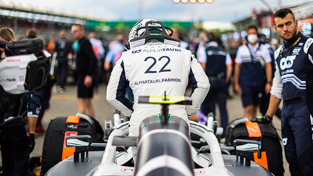
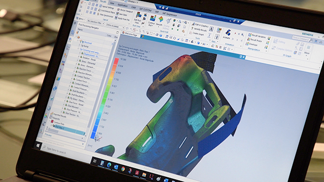
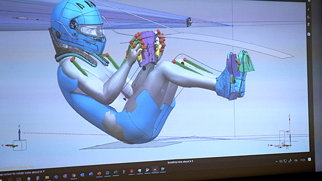
Data is king: any piece of information the team can analyze will help them understand the performance behavior of the new car.

“Each carbon part is a laminate, so we need to make sure the first one is the same as the last one. This is why we use Fibersim. We save time during the production process with this comprehensive simulation. We can prepare plies to be the same for all laminations.

“With Fibersim, we know what is happening in the component. We know the quality standard of the plies. We follow every single ply during the process. We can prevent problems before they happen because we ‘live’ in the same platform from NX to Simcenter to Fibersim. And more importantly, we save time,” says Rizzo.

“The problem with F1 especially – but even for standard cars – is that you need to produce the same part with the same quality at the same time. If you use the same suite that calculates everything for you from the CAD part to the production line, then you end up with a quality part that will deliver performance on the track. That’s the goal,” says Boschetti.

Thanks to Siemens Xcelerator tools like NX, Simcenter and Fibersim, the team can customize each seat to the driver using layers of composite plies to create a hyper-light-weight laminate that performs well to achieve safety and design specifications for the new Scuderia AlphaTauri cars. This provides Gasly and Tsunoda with the ideal connection to the car they need to perform well. Thanks to some superb engineering from the team in Faenza, Italy, and help from the Siemens Xcelerator portfolio, the Scuderia AlphaTauri team is more than ready for the upcoming F1 season.

How a mountain bike enthusiast designed and manufactured his custom carbon fiber bike from scratch with Siemens NX

Product: NX CAD
Industry: Academic

Siemens is not only offering products to big companies, but also small and medium businesses and even private persons can subscribe and benefit from the Siemens Xcelerator portfolio of software and services. This is what this case demonstrates:

We recently found out about the project completed by a German mountain bike enthusiast, who calls himself Uncle Bob, and his journey that started with an empty screen and ended with custom self-built carbon fiber mountain bike.

Uncle Bob’s journey

Due to an injury from biking, Uncle Bob needed a new project to keep himself entertained. He is the founder of an engineering consultancy, which is why he owned the Siemens NX CAD software and has experience with it. So, in his free time he just started directly scribbling in Siemens NX with a try and error approach and with the following weeks, his ideas became a solid concept. 

mountain bike in forest

Bob was especially delighted with the plentiful and individual 3D visualization options NX had to offer, they enabled him to work creatively and to see the realistic result of his design before building. 

Considering the design, Uncle Bob has gone for a form follows function approach: “If something already looks like something that will not last, it surely will not last during tests.” 

Why NX?

Apart from the design aspect, he really appreciates NX for the ability to test and verify his CAD design data into finite element analysis (FEA) simulation tools, which he uses in his daily professional life as well as with this bike. “I have not regretted the investment for Siemens NX, it was worth it and definitely helped me to ease up processes. Before NX, I had to copy data manually from program to program. The implementation of NX at Daimler got me starting to look out for better solutions.” 

bike model inside of nx

So, an FEA study was done to stress test the frame and structure. After all, mountain bikes like these need to withstand high physical forces due to big jumps, loose ground and high speeds. And his bike did!

For example, his calculations resulted that the frame around the bottom bracket can withstand jumps or falls with more than 6,000N. For the areas that failed his tests, the layup of the composite material was modified in Siemens NX and additional plies were added to strengthen these areas.

Getting started and getting building with NX

bike model mold

With a flaw free concept ready, he designed an injection mold in Siemens NX that he could use for producing the carbon-fiber parts. Due to the extensive 3D features in Siemens NX, he could make the mold as material efficient and small as possible.  Then he started working in his garage: A wax core was casted that represents the inner geometry of the carbon frame. Then, he wrapped the carbon fiber around it and closed the mold airtight. Using vacuum and high pressure a hardening resign was injected into the mold. After a few hours of tempering the resign was hardened and with higher temperature the wax core melted and flowed out. Now the frame was made. He didn’t clearcoat the frame because Uncle Joe was confident enough that his construction and his materials used were sufficiently durable anyway.

After that, the frame was made and he started to assemble all the custom frame parts and bought standard parts together. A few weeks later it was all done, a extreme mountain fat bike, that all-in-all only weighted 17kg, with the NX constructed custom carbon forged frame only taking 3kg part of that. After his first test ride, Bob was beyond impressed:

“Insane! Sore muscles in the face because of the permanent grin. I can only say: Dreamy. The bike fits me like a glove.”

An introduction to Composite Structures, with Elston Engineering Services

Product: NX
Industry: Marina

We live in a world where nothing stands still. Companies and individuals across the world continue to push the boundaries of composite structures. After all, it was an engineer, not a scientist, that first set foot on another world. Elston Engineering Services (or EES) are most certainly classed in that bracket of innovators. Based in Knebworth in the UK, EES operate in the world of mechanical engineering services. The company specializing in the development of fibre reinforced plastic composite structures. Ron Elston, Managing director, proudly owns the company. Ron has a wealth of experience spanning over an illustrious 60-year career. His career began as an apprentice draftsman at ML aviation, before eventually overseeing the creation of small integrated circuits and large earth station antennas. Rons’ varied experience means he is considered a specialist within mechanical engineering and composite manufacturing.

To provide context, composites are a combination of non-metallic and metallic materials to create a structure, or range of structures. These structures create strong, lightweight, stiff and low-density components. These components lay the groundwork to create incredibly strong assemblies across a wide range of sectors, including architecture, automotive and aerospace to name a few. It’s an approach which has accelerated the capabilities of society to take our engineering capabilities to the next level.

21st century advanced manufacturing and composite applications; how did we get here?

There was a time when composite manufacturing applications were unable to meet the needs of many companies. Companies had a broad understanding of how new processes and materials would revolutionize the manufacturing workflow to include composites. The problem was, companies weren’t pro-active enough in order to facilitate change.

Ron had an opportunity to merge the testing and analysis of composite structures with the design office during his time at the Marconi Research Centre. Why was this so important at the time? It enabled a specialist like Ron to implement an integrated approach; whereby one team oversaw conceptual design, geometric design, structural analysis, tool creation, part creation and testing. By connecting the dots, composite manufacturing companies were able to achieve greater product innovation to improve production efficiencies. In addition, companies reduced the time to the final iteration, whilst simultaneously pushing the capabilities of their respective industries forward.

Technology was a gamechanger for composite structures

Ron’s experience contributed to a change to processes which resulted in improvements within advanced manufacturing. However, it was the improvements in technology that really pushed the industry into a new era. Modern day capabilities means graphical analysis is completed at a much faster pace. In addition, multiple composite materials can be handled simultaneously; mainly due to improvements we have seen in computer hardware performance and storage.

Shock and vibration studies are now more accurate than they’ve ever been; when you combine all these elements, the user is receiving far more real-world data than previously. Teams who have the experience and/or a knowledgeable will really pay dividends. Composite manufacturers are able to reduce mass, cost and production times for their structures. As a result, the same manufacturers are ultimately reducing their lead time to market.

Sustainability in composite manufacturing

Processes and technological innovations have continuously pushed industry standards to where we are today within composite manufacturing. However, a global transition towards a more sustainable society is needed; composite manufacturing is not immune to this.
Thankfully, composite manufacturing companies are already considering the practicalities of implementing sustainable technologies into their workflow. Companies are beginning to reclaim carbon fibre from decommissioned, out-of-use products in some instances. In addition, there’s been a switch towards the use of thermoplastics as opposed to thermo-setting plastics. Thermosetting plastics for composites typically incorporate one use epoxy resin, Thermoplastics such as polyethylene don’t have this problem; their chemical structure means that they can be re-melted and taken back out of composite structures for re-use. It’s essentially an early stage of a ‘circular economy’ within the composite manufacturing industry.

Fibre-reinforced plastics can produce structures with strength to weight ratios greater than traditional materials, such as steel and aluminium. Reinforcing the thermoplastics using either re-used carbon fibre or ‘virgin’ fibre can achieve strength and stiffness properties approaching those achieved with thermosetting composites. We are seeing continuous improvement of raw materials to create strong products, whilst not compromising on quality and reducing carbon emissions in parallel. This is truly the start of composite manufacturers recognizing the dangers posed by carbon emissions moving towards a more sustainable model for the future.

Why Siemens for composite structures?

For someone with Rons’ experience, using a powerful software application is just as important as having a strong understanding of the science behind composite structures. 50 years in the industry means Ron has seen, used and mastered a range of software applications. It is therefore testament to Siemens that NX continues to be the package of choice for Elston Engineering Services. Why is this the case?

The integrated approach of Siemens NX

Ron believes that Siemens has an integrated approach with NX; different features with different purposes are packaged into the same application to enable users to stay on one platform for their whole workflow. Design engineers can lose precious time during their workflow exporting datasets to another application, if their primary application doesn’t come equipped with the correct features they need for their use case. Siemens NX eliminates this problem. Factoring in a consistent development strategy which add a range of features into future NX releases lays the groundwork for NX to meet the needs of multiple companies across a range of industries.

Understanding the science behind composite structures

The user may have a strong understanding of the science behind composite structures. They then need to have the tools available to accurately simulate the science within their application. It’s an important aspect to any application when analyzing how a range of composite structures will behave in real-world scenarios. This is especially true when the scenario becomes extreme and place enormous external pressures on the structures! NX accurately analyzes composite and metallics structures in accordance with real-world scenarios. It’s a feature that came into its own when Ron developed radar antennas with EASAT for use in intense weather zones.

Rotor Bike Components Innovates with NX

Product: NX
Industry: Costumer Products

A history of innovation

Rotor Bike Components is a group of companies specialized in the design and manufacture of parts for medium- and high-performance bicycles. Recognized worldwide, the company has developed four main product lines – plates, potentiometers, cranksets, and bottom brackets – to which they apply maximum innovation in order to compete in a market that is constantly evolving.

With headquarters in Madrid and a presence in 47 countries, the company has branches in Taiwan, the Netherlands, the United States, and a network of more than 5,000 points of sale worldwide. Rotor Bike Components also has two distribution companies: Bikemotiv for Spain, and Rotor Benelux, which caters to Belgium, the Netherlands, and Luxembourg. In 2014, the company closed the year with revenues of €14 million (85 percent of the total coming from exports) and a team of almost 100 employees.

Innovation is in the DNA of Rotor Bike Components. The company’s genesis took place at the School of Aeronautical Engineers of Madrid (Escuela de Ingenieros Aeronáuticos de Madrid), where, in 1995, a group of students conceived a system of connecting rods with revolutionary biomechanical advantages called Rotor System.

Within the business environment, they continued with other innovative releases such as RCK, a frame with a bottom bracket designed specifically to reap the benefits of the Rotor System. Most importantly, the company also created QRings, ovalized chainrings with varying drivetrain resistance to overcome the dead zone and optimize power output during pedaling. This innovation made Rotor Bike Components a benchmark company in the industry internationally.

“Traditionally, the chainrings were round, but we discovered that an oval shape improved performance and decreased muscle fatigue,” explains José Luis Sanz, director of sales at Rotor Bike Components. “We’ve become popular in the market for being able to adjust the plate and give maximum ovality in different positions, depending on where the maximum power is applied when pedaling.”

Cutting-edge technology supports growth

Innovation continues to affect the day-today operations of the company. The interest in offering solutions with the best technology to improve cycling performance is combined with the challenge of producing more than 250,000 components a year with more than 500 different references to cover their road, triathlon, mountain biking and cyclocross supply.

To sustain innovation, it is essential to align the efforts of Rotor Bike Components’ engineering department with manufacturing professionals from their sister company, EDR System, which is a member of the same corporate group. In the 1990s, EDR System became the first firm in Spain to use aluminum and titanium for the manufacture of bicycle parts, and is a technology leader in computer numerical control (CNC) machining.

“We move within a market of very established brands where our competitive weapon is to offer innovation. It’s important to be very agile in order to quickly adapt to change. You have to be very flexible because the average half-life of products is less than 3 years,” notes David Martínez, director of the engineering department at Rotor Bike Components.

Upgrading design technology

In 2007, the company decided to evolve its computer-aided design (CAD) system, I-deas™ software, to NX™ software from product lifecycle management (PLM) specialist Siemens Digital Industries Software in order to become more competitive. The company faced two key challenges: integrating CAD with computer-aided manufacturing (CAM), and dealing with increasing product complexity. “On one hand, there was no connection between our CAD program and the CAM program of EDR System, and, on the other, the designs were increasingly more complex, especially in addressing assembly, and we needed a tool that was more powerful,” explains Martinez. “We wanted to grow, but without the advanced technology that NX offered us, we couldn’t offer the innovation that would set us apart,” adds Sanz.

After evaluating other solutions the company opted for NX CAD, mainly due to the excellent experience of its sister company, EDR System, which uses NX CAM as a machining solution. NX was introduced to Rotor Bike Components by Análisis y Simulación, a Siemens Digital Industries Software solution partner that shared its extensive knowledge of computer-aided design, engineering and manufacturing (CAD/CAE/CAM) with the company. “We decided to also incorporate NX in our engineering department to take advantage of its design capabilities with multiple advanced features, and ensure total connection with manufacturing processes,” says Sanz.

Maximum collaboration with NX

Currently 99 percent of all Rotor Bike Components’ designs are developed with NX CAD. The engineering team has six licenses, and uses the modeling and drafting tools of the software to perform their 3D design, document generation, and drawing plans for parts and assemblies. The design files are sent to EDR Systems for machining and integrated with their NX CAM system. And for new product development, the department of engineering and quality at Rotor Bike Components evaluates the manufactured models for compliance with appropriate regulations.

“Our process not only brings engineering to the work developed with NX, but also includes quality assurance and third-party companies with which we collaborate for various certifications. It also helps to incorporate elements that we do not make ourselves, such as the electronics for the potentiometers,” says Martínez. “It is critical that we can make exchanges without problems in the same file where the modeling, drawing and machining is integrated, in order to easily execute any change that is asked for, or to integrate any file that is sent to us using the extensive import and export capabilities.”

Within the company, a collaborative environment has been created using NX in which the production team also participates by designing the equipment of certain assembly lines, thanks to a floating license hosted on a corporate server. “This option is very interesting, since the production personnel use the tool in a sporadic way,” says Martinez. “It’s also used for making user manuals, for packaging design, for illustrations in patent applications, and other tasks.”

Martinez appreciates the simple, intuitive use of NX that allows for interface personalization and customization. “Análisis y Simulación gave us the proper training in order to take maximum advantage of it in a simple way,” he says.

Synchronous modeling accelerates design

The synchronous modeling tools of NX facilitate modeling, and allow for maximum speed in implementing quick changes, even without a data structure tree. “This feature together with the assurance that we can import any file extension is critical for re-use of models that we already have, especially the regulation files,” Martinez says.

Optimizing engineering with simulation

Engineering also counts on the analysis and simulation capabilities of NX computer-aided engineering (CAE) to optimize their work. “Knowing that NX was modular and that we could integrate different features according to our needs without having to change the system was a determining factor in our decision for NX. The application of the finite element method is going to continue to add more value to our processes, and it’s something that we already have.”

Siemens solutions assist in the design of an innovative marine stabilizer system

Product: NX CAD
Industry: Consumer Products and Retail

Siemens Digital Industry Software solutions help marine manufacturer reduce testing time by up to 20 percent

Stability at sea

If there’s anything that can spoil a relaxing trip on the water, it’s an unstable boat. Choppy surf can cause significant damage to personal belongings as well as the boat. Whether you’re fishing, scuba diving or just out on the water, ship stability is an essential part of safe sea travel. As a result, ship stabilizers are valuable commodities. Any experienced sailor understands the importance of marine stability in ensuring a sound trip at sea; however, not every stabilizer system is perfect. In fact, a common issue with conventional fin-driven stabilizers is insufficient roll dampening at lower speeds and protruding fins. This issue has hampered the consumer experience. Stability is necessary at low speeds, and protruding fins can become damaged in shallow waters. The last thing your customer wants is to be out at sea when their new stabilizer fails. Considering consumers have a low tolerance for product failure, one bad experience may be all it takes for consumers to jump ship from your product. Only the stabilizer manufacturers who deliver consistent quality survive.

Realizing opportunity

Located in ‘s-Hertogenbosch, Netherlands, DMS Holland is an international specialist in the field of motion control on yachts of up to 30 meters. DMS Holland’s goal is to reduce the roll movement of yachts to improve onboard comfort, reduce sea sick-ness and improve safety. The speed in which DMS Holland’s marine stabilizer systems achieve stabilization differentiate themselves in the market. Their stabilizer systems are based on the Magnus effect, a phenomenon in which a rotating cylinder works away from its principal paths of motion to achieve stability. Where a traditional stabilizer requires a yacht to be traveling at a considerable speed, their product achieves stabilization at just 3 to 12 knots. This differs from conventional fin-based systems due to its small design and greater roll dampening abilities at lower speeds. Brabant Engineering, a mechanical engineering company in Best, Netherlands, is responsible for the design and development of DMS Holland’s Magnus Master, the newest generation of rotor stabilizing technology which features retractable rotors that eliminate the risk of damage. The company is providing DMS Holland with their design expertise to develop the forward-thinking product they envisioned.

“DMS Holland wanted to provide the highest level of stability, comfort, and safety onboard. Overall, we wanted to make life at sea much more comfortable and easy,” says Patrick Noor, sales and marketing director, DMS Holland. “To realize our vision, we need quality companies such as Brabant Engineering to assist us with the mechanical engineering for our stabilizers.”

Sailing toward solutions

Brabant Engineering utilizes the innovative design applications found in Siemens Simcenter™ 3D to accurately design and simulate its projects.

“All the material properties are embedded into the software design, and Simcenter 3D helps us analyze the behavior and durability of our product,” says Bertie Tilmans, lead engineer, Brabant Engineering. “By providing accurate material properties and seamless integration of multiple design alternatives, we can save valuable time during product development.”

Brabant Engineering used Simcenter 3D to accurately simulate the Magnus effect and confirm the Magnus Master could handle 1,100 revolutions per minute. “I have been using Simcenter 3D for the last seven years and I am very fond of the versatility of the software,” says Tilmans. “This versatility allows companies to predict the behavior of different aspects of a product’s design to find the most effective solution.”

Reducing development costs and prototyping cycles

By properly utilizing computer-aided design (CAD) software – such as with their use of Siemens NX™ software – Brabant Engineering uses the powerful and flexible capabilities of NX CAD to drastically reduce the cost and time it takes to design such innovative products. The combination of NX CAD for design and Simcenter 3D for performance prediction help to accelerate product-to-market more efficiently.

Depending on the size of the device, physical prototypes can cost exponentially more than the price of the product. Simulations can save significant time and costs in the early stages of a project. Using Simcenter 3D, instead of relying on a costly physical prototype, Brabant Engineering saved approximately 10 to 20 percent of total testing and qualification time. They were able to shorten the test cycle and receive direct results.

Rikkert Gerits, project leader, Brabant Engineering, confirmed that using Simcenter 3D dramatically reduced the amount of physical prototyping necessary.

“Using 3D simulation tools, we don’t have to build an actual prototype, which saves us considerable time and money,” says Gerits. “We use several Siemens products, like Simcenter, NX CAD, and Teamcenter, and they’re delivered by cards PLM Solutions, a Siemens Digital Industries Software solution partner. We contact them with any specific question we have regarding the software.”

CAD systems offer users the ability to easily interchange various product components. CAD and computer-aided engineering (CAE) systems also provide the necessary tools to rapidly re-engineer and explore the performance of new designs. Gerits explained how these simulation systems also allow for a speedy virtual-proto-typing phase. By simulating the product in real time, users can more accurately predict product durability under certain conditions. This provides companies with significant cost and time savings when compared with designing, producing, testing and recording data of a physical prototype. Brabant Engineering estimates a 10 to 15 percent total cost savings by using simulation to prevent flaws compared to what it would cost to fix/repair those flaws.

Establishing a strong relationship

Sjef van de Laak, managing director, Brabant Engineering, says Siemens solutions are key in the company’s engineering design process. “Siemens is the supplier of the software we use, and the importance of cards PLM Solutions is they know the software very well and support our simulation needs,” he says. Product development would be disrupted without this open line of communication. As such, cards PLM Solutions and Brabant Engineering maintain a constant dialogue.

Sharing the Magnus Master worldwide

The Magnus Master is already receiving considerable attention. Since its introduction in 2015, the Magnus Master has developed a reputation of quality throughout the Netherlands and helped make DMS Holland a global business.

This combined effort between Brabant Engineering, DMS Holland, and Siemens is a perfect example of how cooperation can lead to groundbreaking innovation.

×