Product: HandySCAN Industry: Aerospace and Defense
Lufthansa Technik AG (LHT) is a provider of MRO (maintenance, repair and overhaul) services for aircraft and has 50 locations worldwide. LHT is wholly owned by Deutsche Lufthansa AG and comprises 32 technical maintenance companies and subsidiaries in Europe, Asia and America, along with more than 26,000 employees (as of 2019).
LHT is based at Hamburg Airport. Other important German locations are the two Lufthansa hubs Frankfurt Rhein-Main and Munich as well as the Berlin Tegel Airport (Line Maintenance) and Schönefeld (C-Checks).
Control of Material Expansion
The ARC® – Airframe Related Components division overhauls and repairs fan reversers, engine cowlings, flight controls, aircraft noses (radomes), and other secondary structure composite components. In addition to maintenance work, repair, developments, all types of material support, and logistics solutions are provided. These services are offered for civil aircraft and nearly all popular aircraft types.
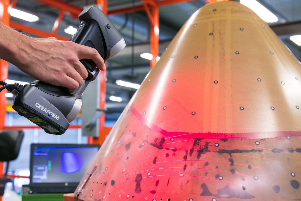
To repair the above-mentioned components, adhesive trays made of carbon or glass fiber are used. Shapes and contours must be checked regularly. The production process takes place under the influence of pressure and temperature variations in an autoclave, so that the material can expand. The extent of the expansion is determined by periodic scans. It is not a one-off project—but a regular measure to ensure quality standards.
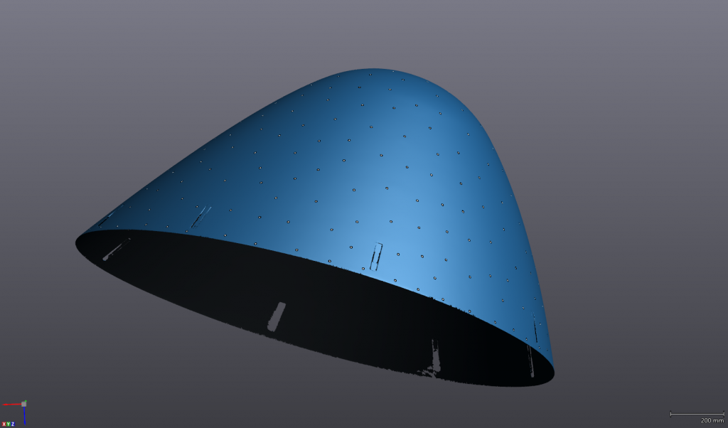
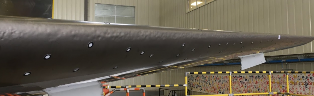
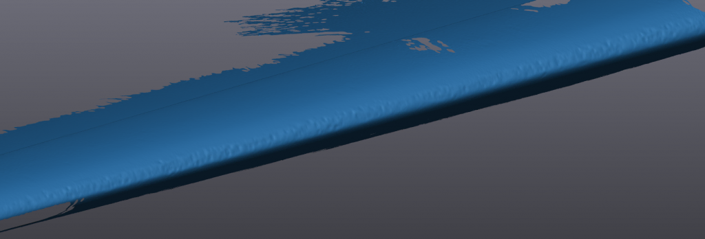
Screenshots of a scanned aircraft nose
The actual state is checked with Creaform’s HandySCAN 3D scanner or, for large objects, with the photogrammetry camera MaxSHOT 3D and compared with a CAD model (target state). On the software side, the data acquisition software, VXelements, is used for data acquisition. On top of providing reliable measurements, Creaform systems are used for other applications, such as reverse engineering, with the help of VXmodel scan-to-CAD software module.
Decision Criteria and ROI
Before LHT started using Creaform systems, measurements, data processing and reverse engineering were provided by a third-party company. The quality of the data as well as the duration of implementation and flexibility in changing conditions led to the decision to purchase hardware and software, thereby building the company’s internal know-how.
Decisive for the choice of the measuring systems were the compactness of the devices as well as the simple data acquisition with the HandySCAN 3D scanner. With these key features, it is possible to capture complex geometries with relatively little effort. In addition, the accuracy for the intended applications is sufficiently high. The MaxSHOT 3D helps to ensure unprecedented accuracy even for larger objects. Currently, the measurement systems are used exclusively in a workshop environment under (mostly) controlled, climatic conditions.
Photogrammetry camera MaxSHOT 3D measures large objects with high accuracy
“The control of the material expansion could have been measured with other common measuring systems, but the price-performance ratio and the compactness of the 3D measuring systems from Creaform made the decision easy. In addition, the customer service is impeccable,” explained Gunnar Hinrichs, who works at the Airframe Related Components Department at LHT. “In terms of ROI, the purchase has also paid off, even if we do not yet have any meaningful data. But it is likely, according to our own estimate, to have a give-figure amount in the lower segment, which we save on outsourcing. If we detect quality deviations at an early stage by using the Creaform technology, we can prevent unnecessary costs and therefore expensive reworking at the customers’ sites.”
Compact, Simple and Flexible
The experience with the Creaform systems is positive. “We can respond much faster and more flexibly to measurement tasks, discuss the measurement results directly at the measured component, and share information with other stakeholders. The systems consistently convince us we made the right decision with their compactness and simplicity of use. A measurement process, including pre- and post-processing (assembly, attachment of the targets, etc.), is completed within 2-3 hours. The data is available in real time. The software interface is well-implemented, understandable and clear. The training provided by Creaform is outstanding and the employees are always available for advice and support. That’s the way you want it to be,” said Hinrichs.
Product: HandySCAN Industry: Aerospace and Defense
US Department of Defense Uses 3D Measurement to Solve Maintenance Challenges
The United States military sector is faced with a host of technical challenges when it comes to maintenance, repair and engineering. Aircraft only have value if they are flight worthy. Personnel responsible for this need efficient and effective means to reduce risks, costs, and maintenance turnaround.
3D scanning instruments and technologies remedy discrepancies due to user errors, they allow for time-saving MRO and reverse engineering operations, and are effective for providing CAD files for 3D-printed replacement aircraft parts and prototypes.
Metrology Hardships in Military: What Can 3D Measurement Do to Help?
Tech. Sgt. Kevin Collins, 366th Maintenance Squadron aircraft metals technology section chief scans an aircraft structure at Mountain Home Air Force Base, Idaho, March 2, 2020. The HandySCAN 3D allows Airmen to scan a structure, eliminating the need to hand draw it on the computer. (U.S. Air Force photo by Airman Natalie Rubenak)
Heavy aircraft maintenance often means long-term grounding, resulting from errors in custom repairs.
Since reliable CAD data is typically not available, the aircraft must be measured to make repairs. Measurement discrepancies typically result from the lack of adequate tools to measure multiple objects and complex surfaces in addition to the challenges to inspect a wide range of part sizes, finishes and colors.
In a nutshell, 3D scanning devices and technologies can be used to accelerate reverse engineering, MRO operations and 3D printing applications, thus increasing mission effectiveness.
Reverse Engineering – Manual to Digital
MRO – Streamlining Inspection and Structure Damage Analysis
Align and Mate: The Bell Helicopter Case
Reverse engineering process: From manual to digital
The 366th Maintenance Squadron (MXS) at Mountain Home Air Force Base (MHAFB) acquired a Creaform HandySCAN 3D handheld 3D scanner to scan large aircraft structures quickly and efficiently.
Prior to using the device, MHAFB Airmen would use “facsimile mold” to fix broken parts or recreate structures. The main issue with facsimile mold is that it takes 48 hours to dry. “When it is done drying, you take it out and still have to go in and measure everything and hand draw it on the computer. It [is] so time consuming,” says Tech. Sgt. Kevin Collins, 366th MXS aircraft metals technology section chief. This tedious reverse engineering process consisting in manually designing models on the computer puts the personnel at the mercy of user errors and premature maintenance.
3D scanners provide the data required to perform full-scale engineering, manufacturing and development of parts and structures. 3D scanning for reverse engineering removes the user error factor and provides unmatched traceability for documentation purposes. Also, device portability means on-site analyses, and reduction of inspection times. 3D scanners are critical tools to support solid reverse engineering processes.
The model above was scanned using a HandySCAN BLACK portable 3D scanner; you can zoom in and see the level of detail around the edges, the holes, the bends and the fasteners. This complex, large part (680 mm X 320 mm X 60 mm) displays several features which would be difficult to measure without 3D scanning instruments.
Another problem faced by MHAFB Airmen is that of accuracy. The mold would often provide little to no accurate results, which would eventually lead to rework and wasted time. “With the scanner, we never run into that issue. In fact, it’s accurate up to about 0.025 mm,” Collins said.
Parts manufactured following this type of reverse engineering process can be quickly and accurately compared to CAD drawings to control 3D dimensional quality.
2. MRO – Streamlining Inspection and Structure Damage Analysis
Fairfield’s Travis AFB, via the 60th MXS, reported using various innovative strategies to improve mission effectiveness and reduce wasted time. The Air Force allocated $64 million in Squadron Innovation Funds to “increase readiness, reduce cost, save time and enhance the lethality of the force,” said Joshua Orr, 60th MXS. Among the new technologies were 3D printing and 3D scanning; the former using the latter to print and replace aircraft parts that suffered damage.
In one notorious case, a C-5 aircraft had been damaged by hail, resulting in numerous dents and scratches on all of the plane’s panels. Every 180 days, Travis Airmen would inspect the aircraft to locate and measure the dents that were still on the wing’s surface. Using traditional measurement tools and methods, performing this task would take around 48 hours. But equipped with a Creaform HandySCAN 3D and SmartDENT 3D, the Airmen were able to complete the inspection in 30 minutes. Unlike manual dent measurement methods, SmartDENT uses good material around damage to create reference surface and provide reliable measures.
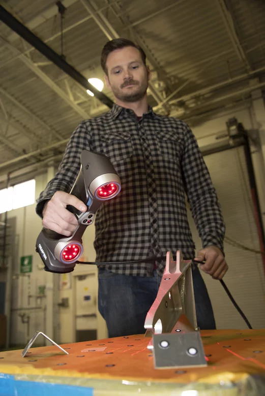
Joshua Orr, 60th MXS, uses a Creaform HandySCAN 700 to capture digital information to render a three-dimensional image of an aircraft part into specialized computer software.
“We had that C-5 in our hangar last week and we were able to inspect the four primary structural panels in 30 minutes.”
Master Sgt. Christopher Smithling 60th Maintenance Squadron assistant section chief for aircraft structural maintenance
Moreover, the procurement of two additive manufacturing units by the 60th MXS will undoubtedly unlock development, repair, replacement and production capabilities at Travis AFB. Aircraft are typically down for two days when a replacement part is needed. However, a solution comprising a 3D scanning device, scan-to-CAD technology and 3D printing can dramatically decrease out-of-service time. “With the two additive manufacturing units, we will be able to grab any aircraft part, scan it, and within four to eight hours, we will have a true 3D drawing of it that we can send to the additive manufacturing unit to print it,” said Christopher Smithling, 60th MXS.
Back to the hail storm matter, Creaform developed a complete 3D scanning solution for the aerospace industry named HandySCAN AEROPACK. It addresses the specific challenges of aircraft quality control, such as assessing damage resulting from aircraft incidents and natural phenomena, like hail, as well as flap and spoiler inspections. The 3D scanner and software package includes VXinspect, VXmodel, SmartDENT 3D and provides the most versatile solution for a maintenance base/MRO facility.
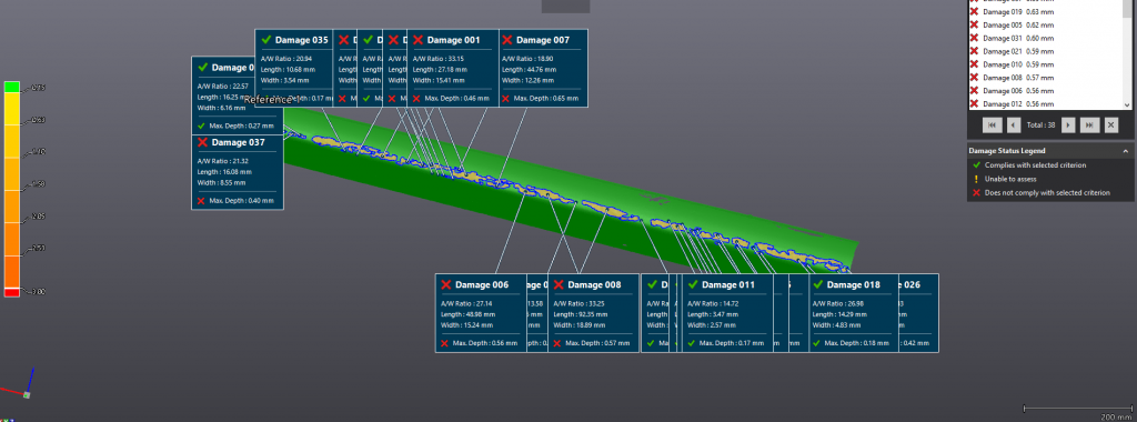
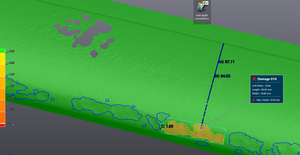
Leading edge of stabilizer of a Boeing 767 damaged by hail3D scan of the leading edge of a Boeing 767 aircraft using a 3D scannerAnalysis of leading edge of a Boeing 767 stabilizer in SmartDENT 3D. Total analysis/reporting time is 30 minutes for full stabilizer damage assessment with a 25-micron accuracy compared to 1-2 days with traditional manual methods.Sample dent inspection on an aircraft. Feature measurements with out of tolerance maximum depth.
3. Align and Mate: The Bell Helicopter Case
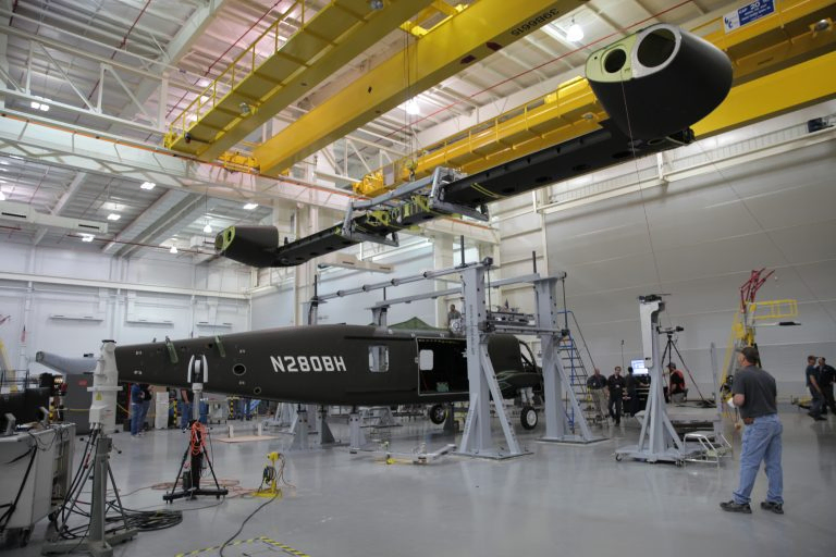
At their Amarillo factory in Texas, Bell Helicopter, a Textron Inc. company, performed the mating of heavy components with the V-280 Valor’s fuselage, a medium-lift tiltrotor transport prototype aimed at “[rekindling] the Army’s interest in tiltrotors.” First, nacelles were attached to the wing, and then the nacelles-wing assembly was attached to the fuselage. These complex operations require vivid attention to detail, bearing in mind the extreme accuracy with which the massive components must be oriented and positioned prior to the mating process.
Multiple C-Tracks and the Creaform VXtrack software module for dynamically tracking multiple objects came in handy to accurately measure the position and orientation of the components of this assembly in real time, as they are assembled (in this case, the tiltrotor’s wing, nacelles and fuselage).
V-280 Valor wing mating at Bell Helicopter Amarillo. Photo courtesy of Bell Helicopter.
Bottom line, the benefits of 3D technologies along with dedicated software are direct and substantial over conventional metrology. Components were positioned in hours, rather than days. Time savings on measurements, increased accuracy, removing user error and unmatched traceability, are just some of the benefits of state-of-the-art measurement technology.
MRO: How to Choose the Best 3D Measurement Solution?
To choose the right 3D measurement solution for your maintenance, repair and engineering project, start by mapping out your current 3D measurement or inspection process, and identify the major, most recurring problems of your workflow and opportunities for improvement.
Of course, accuracy, portability and price all make great impact on decision making, but the more information you can get about the target application and the results you want to generate, the better your choice will be.
Considerations with respect to object dimensions, environment, processing speed and software compatibility will help you find the solution that best fits your needs. That way you will probably be able to start simple and scale things up along the way.
For instance, decision-makers in the aerospace MRO industry will tend to orient their choice based on the fact that the objects to scan are relatively large, that the environment greatly affects the surfaces, and that time is of the essence: the longer aircraft are grounded, the more stakeholders lose money.
Do not hesitate to reach out to various providers to ask for a demonstration and discuss your current challenges with 3D measurement specialists. Creaform offers a full suite of 3D solutions for this type of work: metrology graded, truly portable, fast and versatile. We maintain an ISO 17025 accredited in-house calibration laboratory and can provide unmatched support across the world. Creaform offers traceable solutions that will provide you measurements you can rely on.
Product: HandySCAN Industry: Aerospace and Defense
EADS (European Aeronautic Defense and Space company) is a worldwide leader in aerospace, defense, and associated services. The company has been using Creaform portable 3D measurement products for several years.
More specifically, EADS uses both the HandySCAN 3D and the MetraSCAN 3D optical CMM scanner for scanning tooling and composite parts (carbon/epoxy) and for making parts/CAD comparisons. For its probing needs, EADS uses the HandyPROBE optical CMM. In addition to using VXelements, the data acquisition software behind all Creaform systems, EADS additionally uses the VXtrack module for dynamic measurements, as well as VXlocate, a software module developed through a partnership between Creaform and EADS.
HandySCAN 3D Application Example
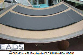
As part of a study on the possible geometric distortion of carbon fiber composite parts and with the help of a HandySCAN 3D device, EADS scanned a 1 000 mm x 800 mm tooling equipment, as well as 650 mm x 300 mm parts, to assess post-manufacturing deformation.
Parts on tooling
First, EADS scanned the tooling, in order to verify its compliance with the CAD plan.
Scanning the tooling with the HandySCAN 3D
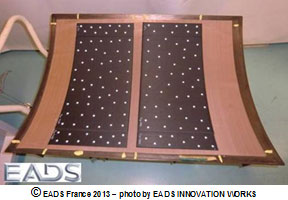
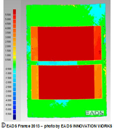
Then, two parts manufactured with this tooling were scanned, and the scanning files were compared.
Scanning the parts and results
Results: tooling/parts gap
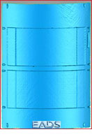
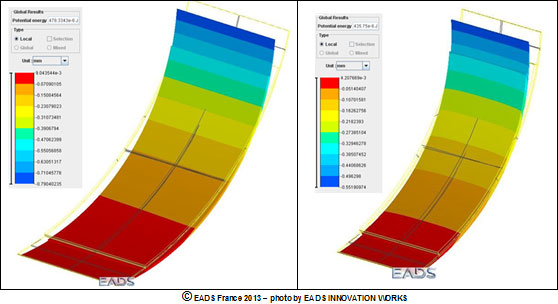
The second step consists of using very powerful simulation tools to estimate the distortion of the parts before manufacturing, in order to compare the manufacturing parts scanning files.
Simulation
The results EADS obtained made it possible to validate the simulation software, which was developed to optimize the manufacturing range by identifying adequate parameters and processes.
This project could have been completed with a fringe projection scanning system, but the one EADS owns cannot be used for such large surfaces, and the process is a lot more complex when it comes to measuring the two faces of the composite parts. Additionally, a CMM could have been used, but this possibility came with two drawbacks: one-off measurements, which in turn lead to a much longer acquisition time.
“ The Creaform system enabled us to quickly scan the metallic tooling and the carbon fiber composite parts. Many other systems that are available on the market do not work very well on these composite parts, which aspect is very dark and sometimes very glossy. The equipment being so portable made it possible for us to record the measurements right at the manufacturing site,” explained Ms. Catherine Bosquet, from the EADS Structure Health Engineering (NDT & SHM) department.
“ Before using Creaform’s systems, we used fringe projection, since we purchased a HOLO3 system over 15 years ago. We also tested other available systems (Konica Minolta, Metris, Steinbichler, Aicon, Kreon Technologies, Ettemeyer, GOM), but the Creaform 3D measurement solutions convinced us, because of their quick set up and acquisition, ease of use, measurement performance for many types of surface states, as well as their portability.We must also mention that Creaform experts are always highly available and responsive.”
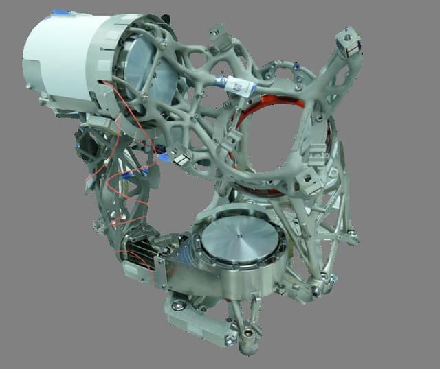
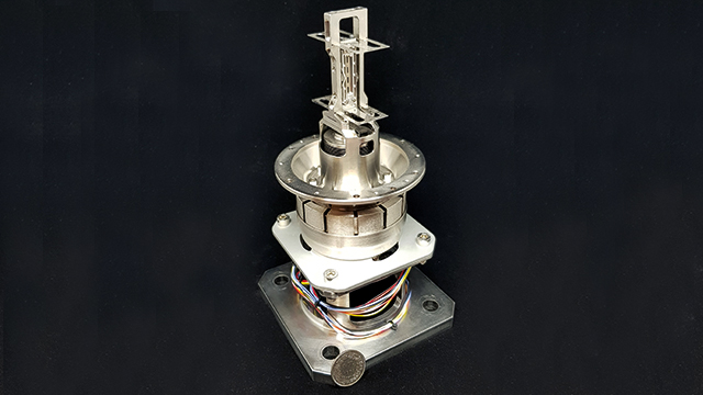
3D Systems collaborates with Thales Alenia Space in the field of design for additive manufacturing (DfAM) to improve performance of a critical sub-system on its Spacebus NEO satellite. The resultant Electrical THruster Mechanism (ETHM) is comprised of seven different additively manufactured brackets. Additive manufacturing (AM) enabled the mechanism to be packaged within a limited volume at the lowest possible mass. Experts within 3D Systems’ Application Innovation Group contributed design and manufacturing know-how to Thales Alenia Space’s ETHM project, packaging their expertise within the final build files that were transferred to Thales’ AM production facility in Morocco. This expert-generated manufacturing plan enabled Thales to seamlessly transition production to its own additive manufacturing facility which is outfitted with several 3D Systems’ direct metal printers.
“Every feature is more or less conventional, but putting them together in a single compact and competitive mechanism is really a challenge.”
Gilles Lubrano, ETHM Product Manager
OPTIMIZE CRITICAL SATELLITE SUB-SYSTEM FOR ACCURACY AND RELIABILITY
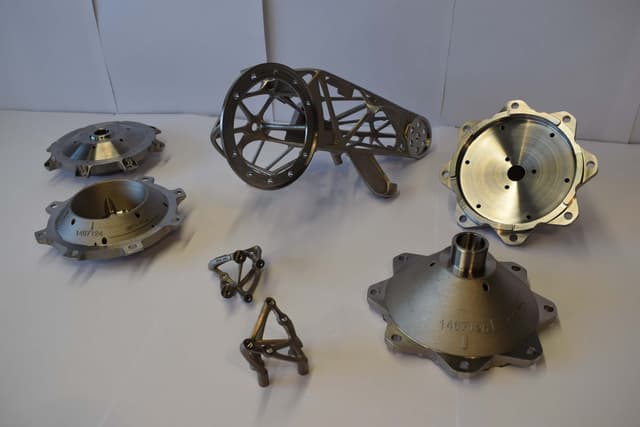
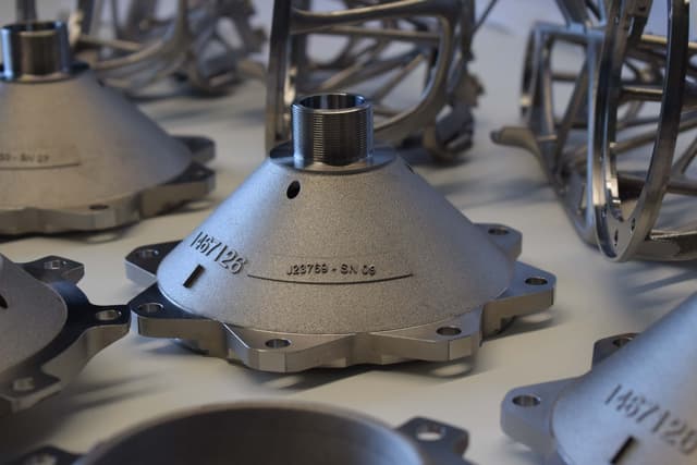
The seven different additively manufactured brackets comprising the ETHM.
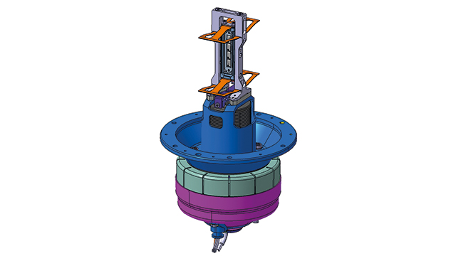
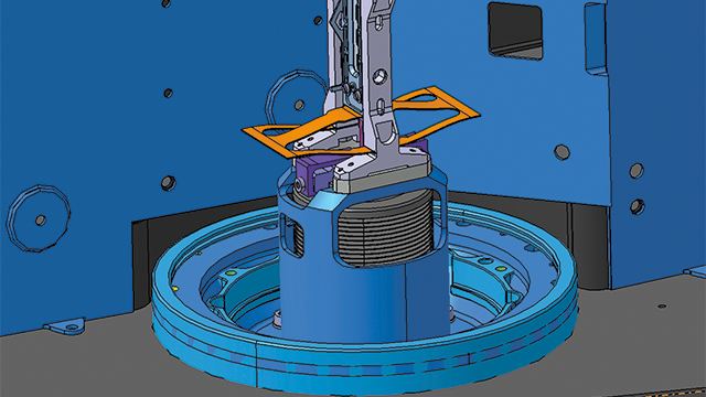
The Electrical THruster mechanism points the satellite propulsion of the Spacebus NEO satellite to correctly position it in space. As such, the reliability of this component is mission-critical. Four ETHMs are required per satellite, forming the chassis around the engines. These parts perform as two axis gimbals holding the electrical propulsion unit, and enabling it to vector with smooth and steady movements.
To meet Thales Alenia Space requirements, the ETHM needed to balance volume and mass constraints while meeting stringent performance specifications, including:
High angle pointing accuracy (0.1-degrees);
Part count reduction including functional integration of various thruster commodities (harness and piping);
Serial production that meets quality requirements for orbital class products.
CONSULTATION AND COLLABORATION FOR SCALABLE PRODUCTION
3D Systems experts helped Thales Alenia Space achieve an optimized strength-to-weight ratio while solving for areas of heat concentration to protect functional components from thermal damage.
Design for Additive Manufacturing Consultation
Thales Alenia Space and 3D Systems have an enduring collaborative partnership, and have worked together to put over 1,700 flightworthy parts in orbit as of 2021. In the ETHM project, Thales Alenia Space partnered with 3D Systems’ Application Innovation Group (AIG) to combine several functions within a small design space while guaranteeing accurate dynamics.
The total dynamic volume allotted for the ETHM is 480 mm x 480 mm x 380 mm, and includes rotary actuators, harness, tubing, and a holding mechanism. 3D Systems provided manufacturability and design feedback to help Thales Alenia Space achieve its performance objectives. 3D Systems experts helped Thales Alenia Space achieve an optimized strength-to-weight ratio while solving for areas of heat concentration to protect functional components from thermal damage.
By using AM to design and produce a system, Thales Alenia Space triggered an expansion of positive impacts. Light-weighting improved thrust efficiency beyond what conventional manufacturing would allow, which in turn improved fuel efficiency, resulting in lower costs and new opportunities for technical innovation elsewhere.
Manufacturing Flow Development
3D Systems helped Thales Alenia Space develop a robust manufacturing flow comprising post-processes like CNC-finishing and 100% tomography inspection to guarantee product and process repeatability in an AS9100 controlled environment. 3D Systems application engineers also provided guidance on the level and sequencing of quality controls for risk mitigation to help Thales Alenia Space ensure a thorough, quality-oriented, and cost-efficient manufacturing flow.
This expertise helped Thales Alenia Space achieve the 0.1-degree pointing accuracy required with an exacting CNC and inspection workflow in which some parts have as many as 249 measurement points taken via coordinate measuring machine that must be in spec. 3D Systems’ collaborative approach included education about the technology along the process of integrated quality controls, as well as root cause analyses of non-conformities against Thales Alenia Space specifications to ensure success. Prior to transitioning production to Thales Alenia Space, 3D Systems helped organize and coordinate a best-in-class supply chain to fulfill series production and produced more than 70 parts at its Customer Innovation Center in Belgium, which is part of 3D Systems’ AIG. The high capacity of this facility and repeatability across 3D Systems’ DMP machines helped ensure a short lead time.
Some parts of the ETHM have as many as 249 measurement points taken via coordinated measuring machine that must be in spec.
Print File Preparation and Transfer
To ensure a seamless transition of ETHM production to Thales Alenia Space, 3D Systems application engineers developed each print file in 3DXpert®, incorporating years of AM expertise that saved Thales Alenia Space time and money while guaranteeing quality. Using these expert-generated build files, repeatable production is possible on any 3D Systems direct metal printer. The final brackets are printed in LaserForm Ti6Al4V grade 23 titanium material.
Several aspects of the thruster mechanism design made 3D Systems’ guidance on print strategy of particularly high value, including:
Maintaining intended roundness of several open structures with large circular interfaces.
Balancing support strength with removability.
Accounting for thermal stresses during the printing process that vary based on the geometry and material printed.
3D Systems’ experience working with titanium materials has helped countless critical applications balance complexity and strength to achieve project parameters. Tools like 3D Systems’ 3DXpert simulation module help support these projects by reducing the number of iterations required to achieve a successful outcome.
Technology Transfer
The final brackets are printed in LaserForm Ti6Al4V grade 23 titanium material.
Thales Alenia Space is now capable of printing these parts at its own facilities following the training and technology transfer 3D Systems has provided over the years. Thales’ group 3D factory in Morocco is outfitted with several 3D Systems’ DMP machines, and took advantage of 3D Systems’ technology transfer offering at the time of installation. Technology transfer is an in-depth, AM-specific training designed to help new printer customers accelerate their transition to AM and safeguard their investment. In combination with the pre-developed build files, 3D Systems has fully supported Thales in its transition to in-house production.
“Using the same machines as the ones in our Customer Innovation Center in Belgium, Thales has simplified its access to a successful print so its team can focus on the industrialization of AM and maximize its return on investments,” said Koen Huybrechts, Manager Application Development, Application Innovation Group, 3D Systems.
BALANCE OF KEY PERFORMANCE CRITERIA FOR OPTIMIZED, SYSTEM-LEVEL DESIGN
ETHM is one of the first full space mechanisms entirely designed with additive manufacturing in mind. The seven different topologically optimized brackets raised the standards of a multi-disciplinary team by their size, the required high precision, and system criticality.
Pointing accuracy of 0.1-degrees ensures mechanism will perform as expected in flight
Increased thruster efficiency from reduced weight of topologically optimized brackets
249 measurement points validated for quality control of most complex part
Integration and protection of thruster commodities for optimal form and function
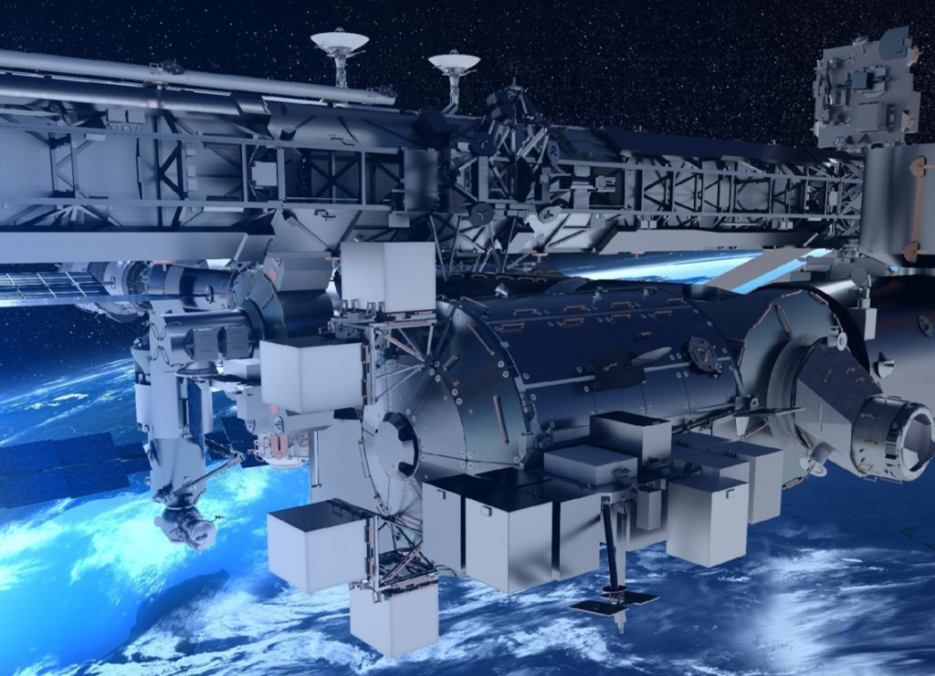
The Spacebus NEO is part of the European Space Agency’s 15-year Advanced Research in Telecommunications Systems (ARTES) Program.
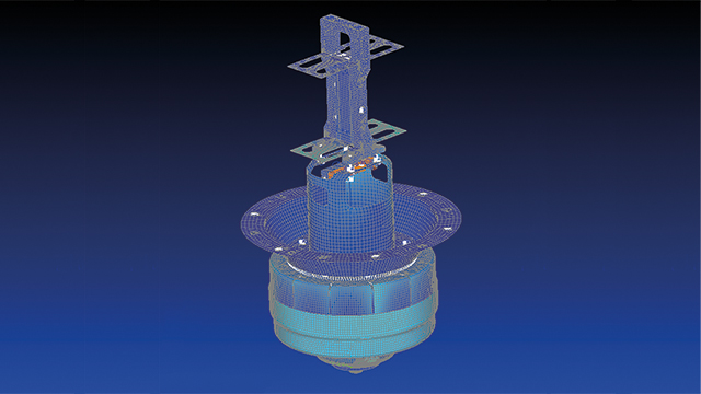
All structures have natural frequencies, and it is often the most important feature of the structure, especially when it comes to dynamic response. Very often the vibrations must be investigated to quantify the structural response in some way, so that its implication on factors such as performance and fatigue can be evaluated.
Modal testing is a very useful and widely used technique to verify and investigate this behavior. It looks at the natural frequencies, mode shapes and damping of a structure and helps engineers understand how a design will respond to different dynamic loads.
In the space industry, this technique is also referred to as modal survey testing and is intended to calibrate and increase the accuracy of finite element (FE) structural dynamics model of spacecraft and space launchers. The validated models are important, among other things, for the prediction of the launcher vibrational characteristics, the aeroelastic stability and the dynamic environments to which payloads and on-board equipment are submitted to during the launch.
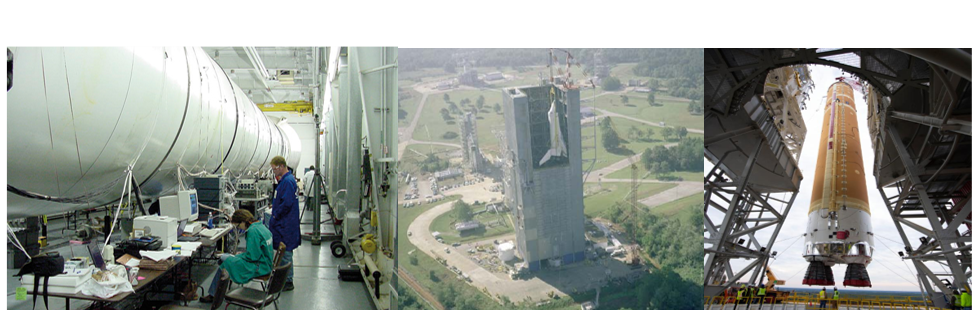
Courtesy NASA: Modal survey testing on Ares launch vehicle (left), Space Shuttle Challenger (middle) and SLS core stage (right)
A modal survey test consists of injecting forces, using electrodynamic shakers or in some cases also a modal impact hammer at a number of carefully chosen inputs. In the case of shaker excitation, burst random excitation is usually used because it is fast and efficient. When higher excitation levels are required, or for the assessment of nonlinear characteristics, stepped sine techniques are used. The forces are measured during the test, along with the response accelerations at many locations throughout the structure. During this test, the spacecraft is mounted in well-known boundary conditions, clamped or free-free, or a combination thereof. During the excitation, FRFs are measured.
After the test, modal curve-fitting technology is applied to extract modal information: resonance frequencies, damping values and mode shapes. The test results are used for the purpose of validating the entire FE model and correlating frequencies, mode shapes and damping assumptions. The significant mode shapes and frequencies are those that are primary contributors to launcher/spacecraft interface loads and internal loads.
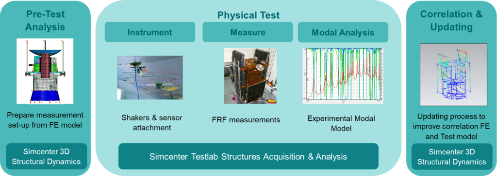
This process is illustrated schematically below. It shows how early FE models of the spacecraft can be used in Simcenter 3D Structural Dynamics to perform pre-test analysis and optimally design the test campaign. Simcenter Testlab and Simcenter SCADAS are then used to efficiently and reliably measure FRFs and accurately determine the best experimental modal model. Finally, the experimental results are further exploited to correlate the preliminary model with experimental results and to update the FE model to better reflect reality.
Different stages of the modal survey process: from test preparation, to the test execution, analysis and reporting.
A good example of a program where a modal survey test was conducted is the Bartolomeo project from Airbus Defense & Space, carried out by Deutsches Zentrum für Luft- und Raumfahrt (DLR). Simcenter SCADAS Mobile hardware has been used as the critical measurement equipment for the modal survey test that was meant to update the FE simulation model of the Bartolomeo platform. This enabled the team to simulate and predict aspects that could only be done using simulation and analysis, such as how the platform would couple with the launcher.
Using Femap makes it easy to reiterate the simulation process.
Dr.Luc Blecha,CTO Almatech
Top precision and maintenance free reliability
To boldly go where no human has gone before was the mission of the starship Enterprise. Its aim was to explore strange new worlds, to seek out new life and new civilizations. While manned space voyages of this magnitude remain fictitious, mankind is sending out space probes to achieve these goals.
During their deep-space missions, typically lasting several years, the satellites are exposed to extreme environmental conditions. These include temperatures ranging from −160 °C to more than 350 °C and acceleration forces amounting to several g as well as high levels of various kinds of radiation. At the same time, there are no gravitational effects such as thermal convection. The on-board instruments and associated fixtures require high precision and operational reliability.
“Although they are optimized for minimum weight, their stability and functionality need to be sustained over several years without any maintenance or cleaning,” says Dr. Luc Blecha, chief technical officer (CTO) of Almatech. Employing 25 scientists and engineers, the company based in Lausanne, Switzerland, develops lightweight structures and mechanical solutions for exceptional requirements such as high precision and reliability in harsh environmental conditions. Almatech is frequently involved in the design of components for spacecraft programs of the European Space Agency (ESA).
Structural components for outer space
Scheduled for launch in late 2019, the Characterising Exoplanet Satellite (CHEOPS) will observe individual bright stars that are known to host exoplanets. It uses a photometer on its telescope to measure the dimming of the starlight caused by a transiting planet. It will provide scientists with the high-precision transit signatures that are needed to measure the sizes of small planets. This data will provide key insight into the formation and evolutionary history of planets.
As part of the Swiss-managed CHEOPS project, Almatech was in charge of all the structural components. The task involved the design and construction of the tubular main structure made of carbon fiber reinforced plastics (CFRP) as well as titanium brackets and the junctions holding the primary and secondary mirrors. The mirrors cannot be adjusted in flight, so their support needs to be rigid and have high stability over the range of temperatures experienced in space.
BepiColombo, a joint European and Japanese mission to Mercury, is already on its way to our inner neighbor. Launched in October 2018, it will start orbiting the least understood planet in our solar system in late 2025. The mission comprises two spacecraft: the Mercury Planetary Orbiter (MPO) and the Mercury Magnetospheric Orbiter (MMO). While gathering data during its one-year mission, the MPO will endure temperatures in excess of 350 °C.
Almatech designed and optimized a baffle that protects the MPO against heating to more than 270°C. It also protects the laser receiver of a built-in altimeter against the heat coming from the sun. The components included a very fine aluminum mirror used to deflect rays of sunlight. “The shape of this mirror was given, the tolerable roughness was specified at 4 nm, regardless of any external influences,” says Blecha. “By comparison, the diameter of one aluminum atom is 0.25 nm.”
The Solar Orbiter is a collaborative mission between the ESA and the United States’ National Aeronautics and Space Administration (NASA) to study the sun and its outer atmosphere. Scheduled for launch in 2019, the spacecraft will observe the sun’s atmosphere and combine these observations with measurements taken in the environment surrounding the orbiter. It will provide insight into fundamental physical processes studied under conditions that are impossible to reproduce on Earth and unfeasible to observe from astronomical distances.
A Spectral Imaging of the Coronal Environment (SPICE) instrument aboard the Solar Orbiter will observe both the solar disk and the corona to characterize plasma properties at and near the sun. For this instrument, Almatech designed a slit-changing mechanism. It moves the shutter by deforming parts rather than sliding along guiding tracks. “This is vital because particles created by abrasion would over time disable the optical instrument, and cleaning is impossible,” says Blecha.
Testing the digital twin again and again
For many parts, Almatech’s role is to optimize existing designs. The CHEOPS telescope structure, for instance, needed to be reduced in complexity and weight while retaining its structural strength. “Because all components we create are unique and need to function for many years without any maintenance or cleaning, development cycles take longer than in terrestrial designs,” says Blecha. “Although the shape of the baffle for the BepiColombo orbiter was given, it took us four years to arrive at the final hardware.” Almatech spent a similar period developing the slit-changing mechanism for the Solar Orbiter, although they were contracted to provide the entire development from first idea to final hardware.
The main cause for these extended development cycles is the enormous number of tests performed to deliver proof that all requirements will be met in all fathomable situations over the entire lifecycle of the components. Within a development cycle, several physical prototypes are built and tested as well, but Almatech performs the vast majority of these tests in the virtual world using a digital twin of the component under scrutiny. For this purpose, the space-grade equipment designers use Femap™ software from Siemens Digital Industries Software in conjunction with the Nastran® solver to simulate performance, starting at very early phases of product development. “The various model analyses provide proof to clients and authorities that the complex devices will perform as required under the anticipated conditions,” says Blecha. “They are also instrumental in our efforts to reduce mass without compromising stability.”
Product: Femap, Simcenter Industry: Aerospace and Defense
Simcenter Femap helps optimize component and parts for Curiosity’s mission to Mars, the most challenging and demanding ever.
Sending a package to Mars is a complex undertaking
Delivering a roving science laboratory from Earth to the planet Mars requires meticulous planning and precision performance. You only have one chance to get it right: there’s no margin for error. Engineers and scientists at NASA’s Jet Propulsion Laboratory (JPL) at the California Institute of Technology had to make crucial decisions thousands of times over a multi-year product development schedule to successfully land the Mars Rover “Curiosity” on the floor of Gale Crater on August 6, 2012. They’ve been doing rocket science at JPL since the 1930s. In 1958, JPL scientists launched Explorer, the first US satellite to orbit the Earth, followed by many successful missions not only near Earth, but also to other planets and the stars.
JPL engineers use a toolkit of engineering software applications from Siemens Digital Industries Software to help them make highly informed decisions. A key component in this toolkit is Simcenter™ Femap™ software, an advanced engineering simulation software program that helps create finite element analysis (FEA) models of complex engineering products and systems and displays solution results. Using Simcenter Femap, JPL engineers virtually modeled Curiosity’s components, assemblies and systems, and simulated their performance under a variety of conditions.
From 13,000 to 0 mph in seven minutes Also known as the Mars Science Laboratory (MSL), this rover is massive compared to earlier vehicles NASA has landed on the “Red Planet.” In the deployed configuration with the arm extended, the rover is 2.5 meters wide, 4.5 meters long and 2.1 meters high. Weighing nearly a ton, the Curiosity rover is five times the mass and twice the length of its predecessors, which meant that an entirely new and much softer landing procedure had to be engineered. NASA needed to slow the rover spacecraft from a speed of 13,000 miles per hour (mph) to a virtual standstill to softly land the rover during what NASA calls “Seven Minutes of Terror.” After completing a series of “S” maneuvers, deploying a huge parachute, and then with the unprecedented use of a specially designed “sky crane,” the MSL was gently set down so as not to damage the labs’ functional and scientific components.
Those components include a 2.1 m long robotic arm, which is used to collect powdered samples from rocks, scoop soil, brush surfaces and deliver samples for analytical instruments. The science instruments on the arm’s turret include the Mars Hand Lens Imager (MAHLI) and the Alpha Particle X-ray Spectrometer (APXS). Other tools on the turret are components of the rover’s Sample Acquisition, Processing and Handling (SA/SPaH) subsystem: The Powder Acquisition Drill System (PADS), the Dust Removal Tool (DRT), and the Collection and Handling for Interior Martian Rock Analysis (CHIMRA) device.
Curiosity also inherited many design elements from the previous Mars rovers “Spirit” and “Opportunity,” which reached Mars in 2004. Those features include six-wheel drive, a rocker-bogie suspension system and cameras mounted on a mast to help the mission’s team on Earth select exploration targets and driving routes on Mars.
Virtually all of the spacecraft itself and its payload were subjected to simulation analysis using Simcenter Femap for pre- and post-processing. Simulations performed before part and system production included linear static, normal loads, buckling, nonlinear, random vibration and transient analyses. Thousands of design decisions were made using information from Simcenter Femap simulations.
In addition to the complex nature of the mission itself, engineers developing Curiosity from initial design to final delivery of components to Cape Canaveral were working against the clock. The ideal time window to send a package from Earth to Mars is a 2- to 3-week period that happens roughly every 26 months. Missing that window would have set the mission back by more than two years, so JPL engineers needed to analyze parts and components quickly and efficiently so that they could be fabricated.
The role of Simcenter Femap
Simcenter Femap is JPL’s primary pre- and postprocessor for FEA. For MSL, engineers started using Simcenter Femap early in the design stage when they were performing trade studies on various configurations or different ways to approach the mission. As the configuration matured, they used Simcenter Femap to help create the master finite element model that was used to run the various load cases.
Most of the structural analysts at JPL use Simcenter Femap either for creating or viewing the results of a FEA run. The software was used for both high level-linear analysis and very detailed nonlinear analysis. These are two very different types of analysis both using the same piece of software.
Certain jobs were simply too large for one person, and in some instances engineers had to build on the work of other people who had previously used Simcenter Femap to build FEA models. Simcenter Femap was designed as a very easy-to-use package, created for analysts by analysts who are acutely aware of what engineers need and how they work. They can pick it up after six months of non-use and be back to peak proficiency in a very short time.
Simcenter Femap was critical in performing all types of FEA on all aspects of the vehicle. Each component of the vehicle had a higher-level, loads-type model built, and these models were joined to create the full spacecraft model. JPL engineers worked through various “what if” scenarios, including as many as 37 different load cases for how the parachute would deploy during the landing process.
The Curiosity mission is not JPL’s only current project. Other missions include satellites monitoring conditions on Earth, telescopes, experiments and other spacecraft.
Planned missions include the InSight mission that will place a lander on Mars in 2016 to drill beneath the surface and investigate the planet’s deep interior to better understand Mars’ evolution. There are even plans for a proposed Mars Sample Return mission, which would collect samples from the surface of Mars and return them to Earth.
JPL engineers are currently using and will likely continue to use Simcenter Femap to help accomplish these and other missions of engineering, discovery and science.
Product: Tecnomatix Industry: Aerospace and Defense
Global aerospace engine supplier deploys Siemens solution to identify production bottlenecks and lower costs
GKN Aerospace Engines, a business line of GKN Aerospace, needed a better tool to plan and optimize their production process and production equipment investment, a tool that would aid in strategic planning, and handle real life complexity to accurately predict lead times and consider variation. GKN Aerospace needed a new avenue to meet customer delivery expectations and identify any existing problems that could be solved before they became unmanageable. In addition, some value streams share production resources between different products, which cause crossing material flows. The production complexity and the daily base decision making, impact the lead time, and created an opportunity for a simulation-based approach, to support a continuous improvement. This led GKN Aerospace to believe that discrete event simulation would perfectly support the company’s different initiatives.
Recognizing a clear need to make their cur-rent processes more efficient, while also considering expected future production volume increases, GKN Aerospace decided to conduct a pilot program using Plant Simulation in the Tecnomatix® portfolio. Plant Simulation enables users to define a virtual model of a production plant, with all its characteristics and inter-dependencies, and use it to simulate actual production. Tecnomatix is a part of the Xcelerator™ portfolio, a comprehensive and integrated portfolio of software and services from Siemens Digital Industries Software.
“We started to use Plant Simulation as we needed a better strategic planning tool to analyze and plan production capacity,” says Alexander Hall, MOM-MES Architect, GKN Aerospace Engines Business Line, TI-IS. “Given the combination of increased fore-casted production volumes and the complexity of our production process, we have realized that the static capacity analysis tools we were using were not accurate enough.”
Pilot project takes flight
The Plant Simulation pilot project was conducted at GKN Aerospace’s plant in Kongsberg, Norway. This plant was selected for the pilot, as production volumes of their TEC/TRF product family were expected to grow significantly, creating the need to conduct a production analysis and adjust the product system to the new expected volume. The engineers in the Kongsberg plant possessed basic experience with discrete event simulation tools before starting the Plant Simulation project. One of their main goals in this virtual production project was to analyze value streams (value stream is GKN Aerospace’s terminology for a product family and its production process) and identify potential problem areas (bottlenecks, which machines are not being properly utilized, etc.) for improvement.
Production simulation with Plant Simulation can consider the effect of variability, an important factor that strongly impacts plant performance. In Kongsberg they have planned and unplanned variability. Examples of unplanned variability include machine failures, lack of material from suppliers, and non-conformance. In an environment with a lot of uncertainties, the simulation is a robust production digital twin that takes into account these issues and, in turn, improves decision making in the areas of machine investment and process improvement. Simulation is also a major component of GKN Aerospace’s digitalization initiative.
GKN Aerospace created a simulation model with Plant Simulation, simulated real-life historical production scenarios to validate the model accuracy, and used the model to test future production volume increase scenarios and options. In addition, the capability of Plant Simulation to visualize the production process in a dynamic 3D environment was powerful as it helped GKN Aerospace’s employees to better understand the layout, production process and material flow.
The Plant Simulation pilot project had three main targets: evaluate the applicability of Plant Simulation for GKN Aerospace, pro-duce a simulation template that will ease the use of the simulation tool in other pro-duction sites and analyze the expected volume increase in one of the plant product families (or value streams). All three targets were met successfully with Plant Simulation.
Another, somewhat unplanned benefit, obtained from the Plant Simulation pilot was that it gave GKN Aerospace a better understanding of how production related data is handled within the company, allowing them to identify several potential areas of important improvements in systems integration and data flows.
Finally, all the insights obtained with Plant Simulation were gained through the creation of a realistic production digital twin model without interfering with the actual production.
“We have a lot of planned and unplanned variability in our plant,” says Ragnhild Hansen, technology/project engineer, GKN Aerospace Kongsberg site. “For example, handling non-conformance is an unplanned activity that has a strong impact on our pro-duction performance. Plant Simulation helps us analyze the impact of variability on the plant performance, as otherwise it’s almost impossible.”
Martin Asp, MOM-MES Architect, GKN Aerospace Engines Business Line, TI-IS says that GKN Aerospace’s production system is very complex and includes variability in both volume and product mix. “It’s a system within a system , with a lot of interdependencies, which makes it challenging to analyze without a suitable tool,” he says. “As such, we have found Plant Simulation is a tool that can handle this complexity and highlight beneficial insights.” GKN Aerospace also used the unique capability Plant Simulation possesses to represent material flow paths and volume with the Sankey Diagram to help demonstrate to their management team the complexity and many interdependencies of GKN Aerospace’s production and material flow. In a Sankey Diagram, the width of a line represents the volume (material or technicians) flowing or moving in this route (a similar concept is common in train or subway maps). An example for the importance of material flow paths analysis is the single heat treatment work cell, which supports several value streams.
Plant Simulation showed GKN Aerospace’s production team that facility equipment breakdown and maintenance was impacting production of their leading turbine rear frame product by only four percent, which contradicted their original projections. On the other hand, Plant Simulation revealed that manual production impacts 72 percent of the lead time, clearly showing where optimization can be most impactful for GKN Aerospace. “We realized we needed to change the static production analysis we were doing to a dynamic one, so we started to use Plant Simulation,” says Mikael Carlsson, MOM-MES Manager, GKN Aerospace Engines Business Line, TI-IS. “We decided to include non-conformance processes in our simulation model. Predicting lead times for rework orders is a challenge for our business. Using different scenarios in Plant Simulation we can see the impact on lead time of different types of rework. By using Plant simulation we were able to identify a bottleneck caused by rework in combination with main production flow. We resolved this by adding a new workstation.” With Plant Simulation, GKN Aerospace can simulate an entire production line and come up with concrete conclusions to potential performance improvements. Such a dynamic simulation considers pro-duction and material flow dependencies between machines and production cells.
“We found the capacity and utilization results obtained with Plant Simulation were 30 percent more accurate than our previous methods,” says Hansen.
Positive early returns
The Plant Simulation pilot project provided GKN Aerospace with a software tool that can handle its strategic target to reduce pro-duction lead time with the expectation it will ultimately result in a competitive advantage since Plant Simulation assists with testing and validating production scenarios, saving time and money.
GKN Aerospace also used Plant Simulation to calculate production capacity and visualize the material flow. The simulation also helped easily identify bottlenecks as GKN Aerospace can run Plant Simulation for any production period (for example, one week). Plant Simulation also helped GKN Aerospace plan production shifts and answer operational questions. “Following the comprehensive Plant Simulation pilot we have conducted in our Kongsberg plant in Norway, we were convinced that Plant Simulation can be used to create a simulation model of our aerospace engines pro-duction processes,” says Karl-David Pettersson, SVP Engineering & Technology, GKN Aerospace Business Line. “It helps us optimize production processes, better utilize our production assets, validate the material flow, reduce WIP and determine when we have to purchase new production equipment to increase production capacity.”
The project was carried out with the support of Siemens consultants, which helped GKN Aerospace to ramp up with Plant Simulation. At some point, a simulation need arose from their U.S. production site as GKN Aerospace was planning to change the product flow and wanted to understand the impact on the delivery to customers. GKN Aerospace engineers built a simulation model to support this, on their own, with-out the help of the Siemens consultants, which was a good sign for the GKN Aerospace ramp up with simulation skills.
Jonas Steen, Director of Technology Insertion Information Systems, GKN Aerospace Engines Business Line, concludes, “GKN Aerospace Engines Business Line produces complex products with exceptionally high quality requirements in a low volume, using very expensive equipment, which is sometimes used for various products. The combination of all this creates a very complex production scenario, such that only an advanced simulation tool like Plant Simulation can handle this complexity.”
To have a more successful buy in of the innovative methodology Plant Simulation offers, the project team made sure to involve the plant production people in the activity. Such an example is the involvement of Daniel Bryn, a shaft value stream manager in the plant, who believes Plant Simulation is an essential means to reduce production lead time, which is a strong initiative. An example of an important simulation need that came from his value stream is the analy-sis of the paint shop area. As the paint process includes a lot of diversified pro-duction processes, it’s not completely straightforward to understand the flow and dynamics within this area, and there was a feeling that only the people that worked there can really understand and optimize it. He asked to analyze how to increase the rate of shafts processed in this area, without increasing the man-power, and indeed, such a simulation was done, revealing promising insights.
In another simulation project for this value stream, they evaluated the intro-duction of an entire automated cell for shafts (robotics material handling, auto-mated turning milling machine, etc.). Plant Simulation helped analyze how the new machines would impact the production sequence, helped compare it to performances of similar machines they already had, and showed how this would impact the existing machines in the line. This activity also proved that GKN Aerospace can reuse a simulation model from one value stream to another.
Plant Simulation also provides value with customer-related scenarios, allowing GKN Aerospace to showcase their innovative production process. “Plant Simulation can be used to show the customer an active production line or a planned concept of a production line in a very dynamic and visualized manner that highlights GKN Aerospace’s innovation,” says Bryn.
As a result of this pilot project, GKN Aerospace can use Plant Simulation in various areas, such as supporting lean manufacturing. Plant Simulation helps GKN Aerospace better understand their value streams and the vast amounts of data the company isn’t fully utilizing. The pilot project also offered GKN Aerospace significant transparency into their production facility and allowed them to better under-stand their processes. Plant Simulation is used both for completely new processes and value streams (greenfield areas), but also to support (continued) improvement of existing production processes. In addition, a few new potential simulation initiatives with Plant Simulation were identified, such as shop floor production space analysis, operational process planning, supporting bid processes and others.
GKN Aerospace also has some thoughts on how they can use Plant Simulation to cope with the new challenges the COVID-19 pan-demic presented. For example, the production digital twin created with the simulation can be used for a lot of virtual reviews and reduce face-to-face interaction of employees. Also, the visualization and simulation of a production line helps to understand the production flow, almost as if you’ve visited the line.
“We have learned that Plant Simulation is a great simulation tool that supports our expected production volume change,” says Pettersson. “It certainly proved its value.”
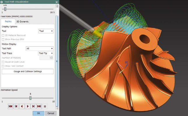
CAD/CAM integration optimizes production data creation
Manufacture of high quality and precision parts with simultaneous and multi-axis machinery
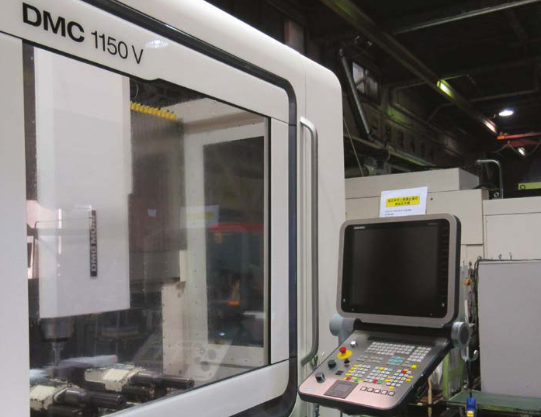
Heiwa Sangyo Co., Ltd. (Heiwa Sangyo) manufactures products that require high quality and precision, including aircraft engines and structures, high-speed rail transport components and rocket parts. The company specializes in simultaneous and multi-axis machinery, in addition to the manufacture of molds. Heiwa Sangyo has a diverse set of machinery tools. In this context, NX™ software from product lifecycle management (PLM) specialist Siemens PLM Software, has become indispensable as a computer-aided manufacturing (CAM) main system.
With operations in Funabashi and Ichikawa in Chiba Prefecture, as well as Komagane in Nagano Prefecture, Heiwa Sangyo uses two other systems besides NX: one exclusively for computer-aided design (CAD) and the other for CAM only. The use of NX as an integrated CAD/CAM system is on the rise.
NX (formerly known as Unigraphics software®) was initially implemented in Heiwa Sangyo in the late 1990s. At the time, the company used a very expensive numerical control (NC) programming system that did not offer a favorable cost-benefit ratio. Heiwa Sangyo had many heavy industry customers and considered expanding his businesses and moving on to manufacturing energy-efficient molding tools. The company chose NX for its lower cost and because it was widely used in the energy-efficient molding sector.
At the time of its introduction, NX was used for mold manufacturing, but also helped Heiwa Sangyo acquire new businesses. “NX is the leading CAD/CAM solution in the field of aircraft engines,” explains Yasuhiro Yao, president of Heiwa Sangyo. “Previously, design work was done in 2D, but from 2000, motorcycle companies switched to using 3D and the tool used was NX. That’s why the use of NX generated new orders for our company.”
CAD/CAM integration accelerates production data creation
Heiwa Sangyo manufactures parts based on design data provided by its customers. Customers usually provide only the model of the finished part with some machinery instructions and other documents. Heiwa Sangyo engineers must create additional data for the manufacturing process, including the design of fasteners and fasteners. “The modeling process for creating manufacturing data is quite complex,” explains Shinichi Ohara, Department of Manufacturing Engineering, Heiwa Sangyo. “With CAD and CAM linking, NX is extremely effective in solving this challenge.”
Heiwa Sangyo uses NX in all processes, from the moment customer data is received until machinery tools are put up and running. In many projects, Heiwa Sangyo must create drawings from designs by using NX’s sketching resources. When machinery involves so many steps and various types of machinery tools, engineers use NX to create work instructions and processing plans. “NX is a complete CAD/CAM solution that we use when we need to move from design and drawing to plant production,” says Ohara.
Working with customer data
In many cases, customer-supplied design data is not in the native NX format. In such cases, the company imports data into NX in common intermediate formats such as the Standard for the Exchange of Product Model Data (STEP) or the Parasolid® software format.
NX synchronous technology modeling resources are particularly useful when working with imported data. “We lose the original parameters when importing the provided data and end up with a model that we can’t review with conventional modeling,” says Ohara. “In that case, the use of synchronous technology allows us to resize holes or move surfaces in models that have no history, so we use it a lot.”
Heiwa Sangyo also uses NX modeling features for troubleshooting when there are incidents when converting data from other systems. Translation problems require additional time to clean up and repair data and can affect the production schedule. Data conversion issues become even more serious when 3D data is provided without blueprints, as the company must work only with the shape data. “Depending on the system used to create the part model, problems such as lack of surfaces can occur when importing data,” Ohara explains. “NX is able to easily read and edit that data, even if there is a problem. NX is very useful for repairing data when conversion problems occur.”
Post Builder achieves maximum performance in machinery tools
Because Heiwa Sangyo is in the real product manufacturing business, the company must be able to create NC code for a wide variety of machinery tools and controller configurations. More than 15 types of postprocessors are needed for the operation of the company’s machinery tools. Creating these processing-res can be very difficult and Heiwa Sangyo engineers use the built-in NX CAM Post Builder resource to improve this process.
Prior to NX CAM, Heiwa Sangyo leaned on other companies to create postprocessors. “With the CAM system we used before, we outsourced the development of the necessary postprocessors for each machine tool,” Ohara says. “We had to buy the processors for each machine tool, but we couldn’t add or change anything for them. One thing we love about NX CAM is its ability to quickly customize postprocessors. It gives users dedicated features in an easy-to-use user interface that responds to requests from CAM users.” Yao sums up the merits of post-processing with NX: “the postprocessor was a black box, but with NX Post Builder we can now create it and adjust it ourselves”.
Reduced to half the training time
In an industry where CAD/CAM usage increases every day, NX helps reduce the cost and time required for staff training. “Other systems are hardly dedicated to CAM or CAD, so you have to learn two tools to use them as a CAD/CAM system. NX is an integrated CAD/CAM solution, so it only requires half the training time,” says Ohara. Features that enable intuitive creation and editing of models, such as synchronous technology, are effective when used by engineers with some CAD skills.
Confidence in system development and support
Prior to NX, Heiwa Sangyo used another CAM system as the primary solution. The other system was considered easier to use for simultaneous multi-axis machines, which is the company’s specialty. However, changes in the continuous development of that system focused more on design functions than cam and the system lost its previous advantages.
“The direction of development (furthest from production) is evident in the characteristics of each system,” Yao says. “At that point, I think NX is a tool that has developed constantly over a long period of time.”
Heiwa Sangyo also values support as one of the key reasons for using NX as its main system. “NX provides valuable tool libraries and tool holders, even for tasks we perform on other systems,” says Shinichi Ohara, who manages the NX operation at Heiwa Sangyo. “In addition to CAM’s core features, NX also supports peripheral technologies such as templates and design libraries used in CAD. I think full support is the most important reason why we’ve been able to use NX our way. We can talk directly to the developer and, for a company of our size, direct communication becomes personal and reassuring.”
Finding the future of manufacturing
Heiwa Sangyo sees many advantages in NX, for example, software compatibility with the advanced resources of the latest machine tools. The company is also attuned to NX’s potential under Siemens, which also manufactures industry-leading machine tool controllers and has a reputation for being a facilitator for complex, high-performance machinery. “Siemens is an established leader in the field of CNC controllers for simultaneous, multi-axis machine tools,” says Yao. “NX is part of the same Siemens brand. From the user’s point of view, this technological integration lays the foundation for solving next-generation problems.”
Heiwa Sangyo is independently expanding the use of NX by linking it to quality control systems. Quality is an important element for companies involved in the manufacture and delivery of real products that meet high consumption standards. Currently, the company uses NX to create customers’ production NC data and send it to machinery tools. Heiwa Sangyo is developing a system to support high-quality manufacturing throughout the process, which will represent a significant competitive advantage. “We want to be able to take a manufacturing result and elevate quality to a higher level by accumulating and analyzing those results,” Yao says.
Product: DMP Printing Industry: Aerospace and Defense
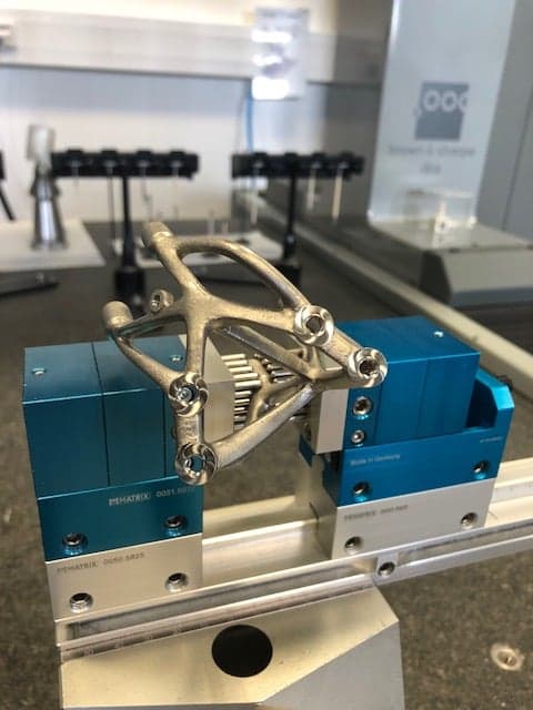
Frustum Inc. software and 3D Systems’ Direct Metal Printing expertise cut aircraft bracket weight 70% while meeting all functional requirements.
The conundrum of balancing the design of a part with the constraints of manufacturing has existed since the Industrial Revolution. Conventional manufacturing techniques have limited capabilities to realize complex geometries or organically shaped components on a cost effective way. This results often in components where functionality and performance are a trade-off.
Now that 3D printing, especially Direct Metal Printing (DMP), has become a viable manufacturing alternative, the constraints imposed by traditional manufacturing have been very much removed. In response to this, software tools for Multi-Disciplinary Design Optimization are now emerging to deliver a convergence point. Topology optimization software is now capable of generating the most efficient designs for one-step manufacturing on the latest generation of DMP systems. Translation? What you model is what you manufacture.
This confluence of technologies was demonstrated recently in a project undertaken by software company Frustum and 3D Systems’ On-Demand Parts service, Quickparts. The project was a publicized challenge by GE Aircraft to reduce the weight of an aircraft bracket while maintaining the strength needed to meet all of its functional requirements, primarily supporting the weight of the cowling while the engine is in service.
The critical nature of weight
Since the beginning of motorized travel on land, air or sea, engineers have striven to balance the demands of weight vs. strength. The balancing act has become more critical in recent years with greater worldwide manufacturing competition, stricter energy conservation measures, escalating cost and delivery time pressures.
Weight is especially crucial for modern aircraft. Although a Boeing 737 weighs approximately 65 metric tons, eliminating only one pound in weight can generate savings of hundreds of thousands of dollars each year for airline companies. Spread that number out to include all aircraft worldwide and the savings are upwards of $10 million according to a GE Aircraft white paper.
Optimizing the design
For the GE Aircraft challenge, Frustum’s software for topology optimization provided the first steps in tackling critical weight vs. strength issues.
Topology optimization determines the most-efficient material layout to meet the exact performance requirements of a part. It takes into consideration the given space allowed, load conditions of the part and maximum stresses allowed in the material.
Frustum’s software automatically generates optimized geometries from existing CAD files. It creates material between the design features to make optimally stiff and lightweight structures. Smooth and blended surfaces reduce weight and minimize stress concentrations.
“Based on an existing conventional part design, our software automatically produces optimized geometry for Additive Manufacturing, without needing to do any remodeling,” says Jesse Blankenship, CEO of Frustum.
Unlike parts manufactured by traditional CNC or casting methods, the complexity of the model generated by topology optimization is of no concern, as DMP handles extremely complex models as easily as simplistic ones. Complexity comes at no cost.
Providing the 3D printing expertise
Once the initial design was generated, 3D Systems’ expertise came into play.
3D Systems’ On Demand Manufacturing service, Quickparts is the world’s leading provider of unique, custom-designed parts, offering instant online quoting, expertise in 3D design and printing, and proven manufacturing services support. This worldwide service is especially well-versed in the more complicated aspects of Direct Metal Printing.
“Direct Metal Printing is much more complex than plastics printing,” says Jonathan Cornelus, business development manager for 3D Systems Quickparts. “We help our customers to develop parts suitable for DMP, with minimized risks for part distortions or build crashes. We print components using optimized parameters based on our long-term experience in printing parts for customers.”
Manufacturing a better part
In the case of the GE aircraft bracket, Frustum’s software took the original CAD file and performed the topology optimization in one step, delivering an STL file.
3D Systems provided manufacturing advice on the process, material specifications, the best build orientation to deliver optimal part properties, achievable tolerances, and identified potential risk for deformations. The part was built on a 3D Systems ProX™ DMP 320 system.
The ProX DMP 320, introduced in early January 2016, offers several advantages for optimizing the weight vs. strength for the aircraft bracket.
Preset build parameters, developed by 3D Systems based on the outcome of nearly half-a-million builds, provide predictable and repeatable print quality for almost any geometry.
A totally new architecture simplifies set-up and delivers the versatility to produce all types of part geometries in titanium, stainless steel or nickel super alloy. Titanium was chosen for the GE aircraft bracket, based on its superior strength even when material is thinly applied to lower a part’s weight.
Exchangeable manufacturing modules for the ProX DMP 320 system reduce downtime when moving among different part materials, and a controlled vacuum build chamber ensures that every part is printed with proven material properties, density and chemical purity. The small portion of non-printed material can be completely recycled, saving money and providing environmental benefits.
An eye opener
The completed part, designed by Frustum and DMP-manufactured by 3D Systems, passed all the load condition requirements specified by the GE challenge and stayed within the same footprint while reducing weight by a staggering 70 percent.
“This is the kind of project that should be a real eye-opener for automotive and aerospace companies, where reducing weight while providing the same or improved functionality is the lifeblood of their design, engineering and manufacturing operations,” says Cornelus.
Beyond the design and performance of the part itself, Cornelus points out that topology optimization teamed with DMP can often consolidate multi-part assemblies into a stronger single part, eliminating fasteners and connectors that are often the cause of failures.
Finally, there is the coveted advantage of speed. Production-grade parts in tough materials such as stainless steel, titanium and nickel super alloy can be turned around by 3D Systems in as little as two weeks to satisfy the ever-quickening pace in myriad industries.


 Photogrammetry camera MaxSHOT 3D measures large objects with high accuracy
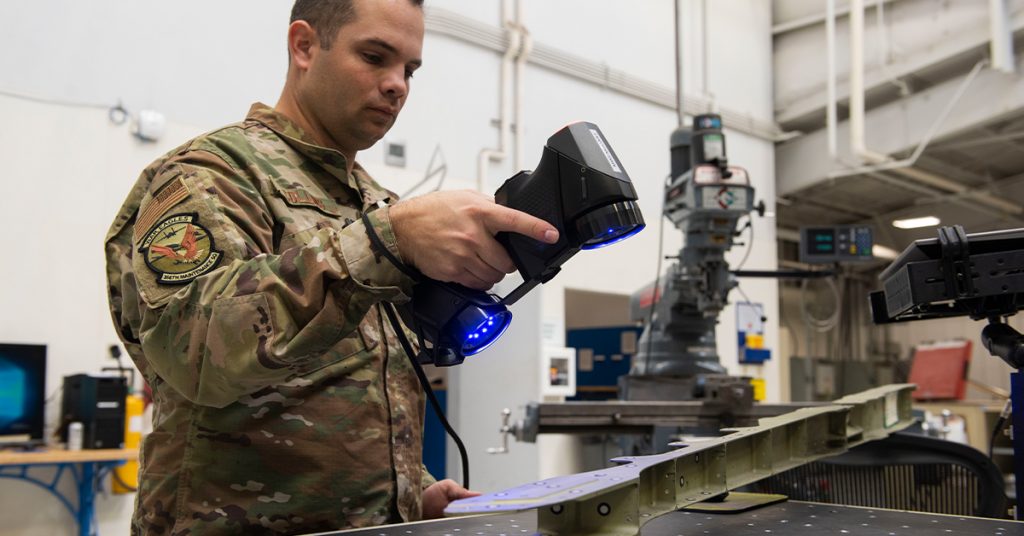


