Industrial diaphragm maker DiaCom achieves seamless transfer of tool design to manufacturing with Solid Edge

Product: CAM Pro
Industry: Industrial Machinery and Heavy Equipment

DiaCom targets new markets demanding higher levels of technology for its complex molded diaphragms

Cutting-edge products, new geographic markets

About six years ago, industrial diaphragm manufacturer, DiaCom Corp. (DiaCom) initiated a shift in its approach to tool design and manufacturing. With a great customer reputation already in place, the time came to upgrade the company’s technologies. The goal: expand into new markets. The Amherst, New Hampshire-based company designs and manufactures innovative, cost-effective molded diaphragms critical to the operation of essential industrial systems and equipment. DiaCom not only produces diaphragms but designs and builds the tooling to manufacture them. The company staffs design and tool departments as part of its business model.

The new technology shifts have allowed entry into new industries requiring more complex diaphragms as well as parallel markets. Those industry targets include aerospace, irrigation, automotive, oil, gas and medical customers. “We wanted to grow dynamically by offering more intricate, cutting-edge products and also expand into new geographic markets in China and Europe,” says Mike Grywalski, manufacturing engineering manager at DiaCom. “There’s more technology demand from these new customers. They don’t just need washers on a garden hose.”

DiaCom customers operate in a different world, with more intricate design demands leaning heavily on parametric modeling to meet government and industry standards. Many of its longtime, established customers now require a similar technological ability to produce more advanced diaphragms.

Design for manufacturing

Expansion required more advanced soft-ware technology. Customers were starting to come to DiaCom with 3D models to work from. The company was using 2D computer-aided design (CAD) software, producing “old-school” drawings that couldn‘t fully define some products. DiaCom recognized the problem and decided to shift its design paradigm.

Grywalski’s shopfloor background helped him realize the need to bring the tool group on board with any CAD technology changes. With many years of CAD and computer-aided manufacturing (CAM) software experience, he recalled compatibility, communication and technical support issues when using software from two different vendors.

“We wanted to bring the tooling group on board with our plans,” says Grywalski. “We wanted to implement CAD and CAM applications from one software company so we could get one-stop support.” The company selected Solid Edge® software for 3D design and Solid Edge CAM Pro software for manufacturing, both from product lifecycle management (PLM) specialist Siemens Digital Industries Software. DiaCom relies on Siemens solution partner Maya HTT for implementation, training and system support.

Move from 2D to 3D design for advanced parts

DiaCom evaluated multiple CAD systems including SOLIDWORKS® software, AutoCAD® software, Inventor® software, Pro/ENGINEER® software and Solid Edge. “While there were many software programs available, we selected Solid Edge because of available support from Maya HTT as well as from Siemens’ Global Technical Access Center organization. This support network paid off well as we initiated changes.” Besides the 24/7 support for both CAD and CAM questions, Maya HTT and Siemens Digital Industries Software helped DiaCom identify postprocessors for its machine tools and solve other hardware/software inter-face challenges.

DiaCom determined that the Siemens Digital Industries Software technology was impressive and pricing was competitive. “Solid Edge gave us the technological capability to design the more complex parts required by existing customers as well as the other new customers we work with,” says Grywalski. “Today‘s changes are often more challenging and can take longer. With 3D, it’s easier to make customer-requested design changes than it was with traditional 2D software.” DiaCom has started to use the synchro-nous technology capability of Solid Edge, applying the simplicity of direct modeling with the control of parametric design. The company continues to evaluate synchro-nous technology as well as traditional ordered design. “In some cases, the ordered approach makes the most sense,” Grywalski says. “At other times, the synchronous approach seems best. Either way, we are seeing a reduction in design time and higher accuracy, both of which have a positive impact on manufacturing. For example, on a recent complex mold project, the use of Solid Edge modeling was 25 to 30 percent faster than traditional 2D design and was more accurate.”

Making modifications to existing diaphragm designs is quite common at DiaCom. By using synchronous technology instead of traditional history-based processes, DiaCom has experienced a reduction in revision time by up to 50 percent on recent design work.

DiaCom is designing programs to create automated part and tool models based on variable tables in Solid Edge. By applying new business engineering processes, these programs are being used by designers to accelerate design without sacrificing accuracy. Though this is in the early stages of development, the company has already experienced significant benefits with the new approach.

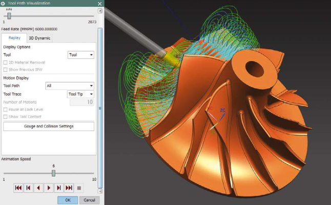
Solid Edge manufacturing

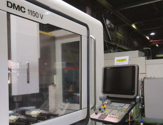
For its computer numerical control (CNC) programming tool, DiaCom selected Solid Edge Cam Pro from Siemens Digital Industries Software. DiaCom uses Solid Edge Cam Pro to program its Okuma CNC lathe and Fadal CNC mill, among other pieces of equipment to machine the compression molds that are used to manufacture the diaphragms. DiaCom’s tool room lead pioneered the use of Solid Edge Cam Pro to program the machine tools. Additionally, the mill and lathe machine operators have been trained in the use of Solid Edge Cam Pro to program the machine tools.

“With 3D CAD in place, we have been designing some pretty complex parts for various applications. Many customers prefer not to use traditional diaphragm designs,” Grywalski says. The more sophisticated designs also required Solid Edge CAM Pro 3-axis machine milling and turning programming capabilities.

The combination of Solid Edge and Solid Edge Cam Pro has provided “a seamless transfer of tool design communication between our design group and the shop floor,” says Grywalski. DiaCom evaluated four CAM packages and is pleased with its choice of Solid Edge Cam Pro.

Other results from the technology upgrades and market expansion included building a new tooling complex and expansion of the design and tool manufacturing staff by about 60 percent.

“Solid Edge and Solid Edge Cam Pro have made a significant difference by improving our technical design and tool-build capabilities,” said Grywalski. “They helped DiaCom provide complex products, which would not have been as easily made several years ago.”

Innovative Surgery Guided by 3D Printing Alleviates Pain for Champion Sled Hockey Player

Product: SLA Print
Industry: Medical and Forensic

When Mark Weimer emerged from the fog of pain medication after major spinal surgery, he didn’t think about how he was feeling. He thought about what he wasn’t feeling: the pain in his quad muscles, emanating from his lower spine, that had plagued him for a year and a half.

The relief was the result of a 15-hour operation by Dr. George Frey that combined his award winning methodology for pedicle screw navigation with 3D imaging and printing technologies pioneered by 3D Systems.

Partnering for the patient’s benefit

Dr. Frey and his wife, Heidi, head up Mighty Oak Medical in Englewood, Colorado. The company’s patented FIREFLY® technology provides a simpler and faster way to accurately place pedicle screws for spinal repair while navigating around crucial anatomy such as the spinal cord, nerves and blood vessels.

From the beginning, Mighty Oak has teamed with the 3D Systems Healthcare Team in nearby Littleton, Colorado.

“We needed a 3D printing partner that was known for quality, reliability and expertise in the medical device space,” says Heidi Frey. “3D Systems has been an amazing partner at every level—they are supportive, responsive and dedicated to excellence.”

3D Systems offers an end-to-end suite of precision healthcare solutions, including virtual reality simulators, 3D printed anatomical models, and patient-specific surgical guides and instrumentation. The company also manufactures precision 3D printed medical devices.

Since the late 1990s, 3D Systems has partnered with medical device providers representing a wide variety of procedures for nearly every aspect of human anatomy. The company has developed personalized solutions for more than 100,000 surgical procedures.

3D printed spine reference model used in the surgery

Path of a champion

Dr. Frey was connected to Mark Weimer through his neuro surgeon who has treated Weimer since his initial operation after a fall from construction scaffolding partially paralyzed him in 1984. Weimer later underwent an additional spinal fusion surgery in 2001 to help correct loss of muscle strength in his right arm.

Following his injury and initial surgery, Weimer took advantage of a computer training grant to become an IT specialist in data warehousing. He also continued to pursue his love of hockey, joining a Colorado sled hockey program in 1996.

Weimer played on the 2000 national sled hockey team in Lake Placid, home of the famous “Miracle on Ice” victory of the U.S. hockey team over Russia in the 1980 Winter Olympics. In 2010, he captained the team that won the Sled Classic Championship sponsored by the National Hockey League (NHL), and the following year he starred on the Colorado Avalanche team that captured the 2011 National Sled Hockey Championship sponsored by USA Hockey.

Weimer retired after scoring a goal and an assist in the 2011 championship. He turned to coaching young sled hockey players and has stayed in shape by hand cycling. His hockey achievements were recognized by his induction into the Colorado Adaptive Sports Foundation Hall of Fame in 2012.

A complicated case

Since his accident, Weimer had always dealt with some level of nerve and spinal discomfort, but in late 2014 he started experiencing something new: severe pain in his quad muscles, along with bowel and bladder problems. Weimer’s neurosurgeon referred him to Dr. Frey for further examination.

“As the years went by, Mark’s spinal fusion and his neurological condition caused the remaining discs and vertebrae below the fusion to deteriorate,” says Dr. Frey. “This caused further compression of the nerves and spinal cord, resulting in severe neuropathic pain.”

Preparation for surgery started with a CT scan of Weimer’s spine. The results were sent to 3D Systems, which performed data segmentation to extract a 3D representation of Weimer’s spinal anatomy.

Weimer’s case was more complex than most other spinal procedures, according to Dr. Frey and Chris Beaudreau, Director of Medical Services at 3D Systems.

“Mark had bone growth over the rods inserted from his previous surgery,” says Dr. Frey. “Although the rods were being removed, any disruption to the surrounding bone could affect the placement of the FIREFLY guides, so plenty of planning was needed to work around the anatomy.”

“Due to his previous surgical procedures, there were significant imaging artifacts within the CT scan that required extensive medical image processing in order to render the anatomical area of interest into three-dimensional digital models,” says Beaudreau. “It was also going to be an extensive spinal procedure, so instead of modeling two or three vertebrae, we needed to process nine vertebrae, the sacrum bone at the base of the spine, and both hips.”

3D printing from the source

3D Systems sent the 3D models of Weimer’s spinal anatomy to Mighty Oak Medical, which used them to design the trajectory of each pedicle screw and to prepare the 3D printed guides that would determine accurate screw placement on Weimer’s spine.

Using the FIREFLY design, 3D Systems printed pedicle screw guides for each vertebra that required operation. An anatomical bone model was also printed for pre-surgical planning and reference in the operating room.

The surgical guides and bone models were printed on a 3D Systems ProX® 800, a stereolithography (SLA) system known for building parts with outstanding surface smoothness, feature resolution, edge definition and tolerances.

SLA technology was invented by 3D Systems co-founder Chuck Hull in 1983. The company continues to innovate with the technology, lowering costs while delivering ever-greater speed, capacity, accuracy and ease-of-use.

The ProX 800 offers a wide range of materials for the broadest applications and use cases. For Weimer’s reference model and screw guides, 3D Systems used a plastic material and validated process that allows parts to be sterilized for use directly in the operating room.

Surgical success and recovery

Dr. Frey operated on Mark Weimer at Swedish Medical Center in Englewood on July 22, 2016. When Weimer resumed consciousness, his most recent pains were gone and previous pains had lessened considerably.

“Mark is currently undergoing a rigorous rehabilitative process and is recovering nicely from his fusion surgery,” says Dr. Frey, who expects the recovery period to last about a year.

At 63, Weimer continues to work in the IT field and pursue hand cycling in his free time. He also enjoys watching his grandsons, ages 9 and 13, take his place on the ice as the next generation of champions.

Heiwa Sangyo: NX supports the entire operation of various machinery tools

Product: NX CAM
Industry: Aerospace y Defense

CAD/CAM integration optimizes production data creation

Manufacture of high quality and precision parts with simultaneous and multi-axis machinery

Heiwa Sangyo Co., Ltd. (Heiwa Sangyo) manufactures products that require high quality and precision, including aircraft engines and structures, high-speed rail transport components and rocket parts. The company specializes in simultaneous and multi-axis machinery, in addition to the manufacture of molds. Heiwa Sangyo has a diverse set of machinery tools. In this context, NX™ software from product lifecycle management (PLM) specialist Siemens PLM Software, has become indispensable as a computer-aided manufacturing (CAM) main system.

With operations in Funabashi and Ichikawa in Chiba Prefecture, as well as Komagane in Nagano Prefecture, Heiwa Sangyo uses two other systems besides NX: one exclusively for computer-aided design (CAD) and the other for CAM only. The use of NX as an integrated CAD/CAM system is on the rise.

NX (formerly known as Unigraphics software®) was initially implemented in Heiwa Sangyo in the late 1990s. At the time, the company used a very expensive numerical control (NC) programming system that did not offer a favorable cost-benefit ratio. Heiwa Sangyo had many heavy industry customers and considered expanding his businesses and moving on to manufacturing energy-efficient molding tools. The company chose NX for its lower cost and because it was widely used in the energy-efficient molding sector.

At the time of its introduction, NX was used for mold manufacturing, but also helped Heiwa Sangyo acquire new businesses. “NX is the leading CAD/CAM solution in the field of aircraft engines,” explains Yasuhiro Yao, president of Heiwa Sangyo. “Previously, design work was done in 2D, but from 2000, motorcycle companies switched to using 3D and the tool used was NX. That’s why the use of NX generated new orders for our company.”

CAD/CAM integration accelerates production data creation

Heiwa Sangyo manufactures parts based on design data provided by its customers. Customers usually provide only the model of the finished part with some machinery instructions and other documents. Heiwa Sangyo engineers must create additional data for the manufacturing process, including the design of fasteners and fasteners. “The modeling process for creating manufacturing data is quite complex,” explains Shinichi Ohara, Department of Manufacturing Engineering, Heiwa Sangyo. “With CAD and CAM linking, NX is extremely effective in solving this challenge.”

Heiwa Sangyo uses NX in all processes, from the moment customer data is received until machinery tools are put up and running. In many projects, Heiwa Sangyo must create drawings from designs by using NX’s sketching resources. When machinery involves so many steps and various types of machinery tools, engineers use NX to create work instructions and processing plans. “NX is a complete CAD/CAM solution that we use when we need to move from design and drawing to plant production,” says Ohara.

Working with customer data

In many cases, customer-supplied design data is not in the native NX format. In such cases, the company imports data into NX in common intermediate formats such as the Standard for the Exchange of Product Model Data (STEP) or the Parasolid® software format.

NX synchronous technology modeling resources are particularly useful when working with imported data. “We lose the original parameters when importing the provided data and end up with a model that we can’t review with conventional modeling,” says Ohara. “In that case, the use of synchronous technology allows us to resize holes or move surfaces in models that have no history, so we use it a lot.”

Heiwa Sangyo also uses NX modeling features for troubleshooting when there are incidents when converting data from other systems. Translation problems require additional time to clean up and repair data and can affect the production schedule. Data conversion issues become even more serious when 3D data is provided without blueprints, as the company must work only with the shape data. “Depending on the system used to create the part model, problems such as lack of surfaces can occur when importing data,” Ohara explains. “NX is able to easily read and edit that data, even if there is a problem. NX is very useful for repairing data when conversion problems occur.”

Post Builder achieves maximum performance in machinery tools

Because Heiwa Sangyo is in the real product manufacturing business, the company must be able to create NC code for a wide variety of machinery tools and controller configurations. More than 15 types of postprocessors are needed for the operation of the company’s machinery tools. Creating these processing-res can be very difficult and Heiwa Sangyo engineers use the built-in NX CAM Post Builder resource to improve this process.

Prior to NX CAM, Heiwa Sangyo leaned on other companies to create postprocessors. “With the CAM system we used before, we outsourced the development of the necessary postprocessors for each machine tool,” Ohara says. “We had to buy the processors for each machine tool, but we couldn’t add or change anything for them. One thing we love about NX CAM is its ability to quickly customize postprocessors. It gives users dedicated features in an easy-to-use user interface that responds to requests from CAM users.” Yao sums up the merits of post-processing with NX: “the postprocessor was a black box, but with NX Post Builder we can now create it and adjust it ourselves”.

Reduced to half the training time

In an industry where CAD/CAM usage increases every day, NX helps reduce the cost and time required for staff training. “Other systems are hardly dedicated to CAM or CAD, so you have to learn two tools to use them as a CAD/CAM system. NX is an integrated CAD/CAM solution, so it only requires half the training time,” says Ohara. Features that enable intuitive creation and editing of models, such as synchronous technology, are effective when used by engineers with some CAD skills.

Confidence in system development and support

Prior to NX, Heiwa Sangyo used another CAM system as the primary solution. The other system was considered easier to use for simultaneous multi-axis machines, which is the company’s specialty. However, changes in the continuous development of that system focused more on design functions than cam and the system lost its previous advantages.

“The direction of development (furthest from production) is evident in the characteristics of each system,” Yao says. “At that point, I think NX is a tool that has developed constantly over a long period of time.”

Heiwa Sangyo also values support as one of the key reasons for using NX as its main system. “NX provides valuable tool libraries and tool holders, even for tasks we perform on other systems,” says Shinichi Ohara, who manages the NX operation at Heiwa Sangyo. “In addition to CAM’s core features, NX also supports peripheral technologies such as templates and design libraries used in CAD. I think full support is the most important reason why we’ve been able to use NX our way. We can talk directly to the developer and, for a company of our size, direct communication becomes personal and reassuring.”

Finding the future of manufacturing

Heiwa Sangyo sees many advantages in NX, for example, software compatibility with the advanced resources of the latest machine tools. The company is also attuned to NX’s potential under Siemens, which also manufactures industry-leading machine tool controllers and has a reputation for being a facilitator for complex, high-performance machinery. “Siemens is an established leader in the field of CNC controllers for simultaneous, multi-axis machine tools,” says Yao. “NX is part of the same Siemens brand. From the user’s point of view, this technological integration lays the foundation for solving next-generation problems.”

Heiwa Sangyo is independently expanding the use of NX by linking it to quality control systems. Quality is an important element for companies involved in the manufacture and delivery of real products that meet high consumption standards. Currently, the company uses NX to create customers’ production NC data and send it to machinery tools. Heiwa Sangyo is developing a system to support high-quality manufacturing throughout the process, which will represent a significant competitive advantage. “We want to be able to take a manufacturing result and elevate quality to a higher level by accumulating and analyzing those results,” Yao says.

×